1
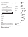
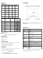
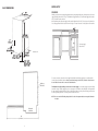
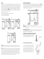
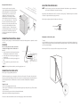
Viking Installation Guide
Viking Range Corporation
111 Front Street
Greenwood, Mississippi 38930 USA
(662) 455-1200
For product information,
call 1-888-VIKING1 (845-4641)
or visit the Viking Web site at
vikingrange.com
UL
F20244D
#8078394
C
UL
(010708J)
Undercounter Dishwashers
IMPORTANT - PLEASE READ AND FOLLOW
•Before beginning - please read these instructions completely and carefully
•Do not remove permanently affixed labels, warnings, or rating plates from the dishwasher. This may void warranty.
•Please observe all national and local codes.
•Please ensure that this product is properly grounded.
•The installer should leave these instructions with the consumer who should retain for local inspector’s use and
for future reference.
WARNING!
Make sure that incoming voltage is the same as unit rating. An electric rating plate specifying voltage,
hertz, wattage, amps, and phase is attached to the product. Wiring the dishwasher with more voltage than
it is rated for may cause severe damage to the thermistor, element, and other components. Wiring the
dishwasher with less voltage than it is rated for may cause significant decrease in performance. To reduce
the risk of fire, electric shock, or injury to persons, installation work and electrical wiring must be done by
qualified people in accordance with all applicable codes and standards, including fire-rated conditions.
TOOLS YOU WILL NEED
1) Phillips No. 2 screwdriver
1)
2) Flat blade screwdriver
2)
3) Torx screwdriver size T 20
3)
4) Adjustable wrenches
(if copper fittings are used)
4)
5) Open ended wrenches
1/2” (1.3 cm) or 5/8” (1.6 cm)
5)
6) Wire cutters and strippers
7) Tape measure
6)
WARNING!
Electrical power must be turned off at circuit breaker or fuse box before connecting any electrical cables.
SEQUENCE OF DISHWASHER INSTALLATION
1.
2.
3.
4.
5.
6.
7.
8.
9.
10.
11.
12.
8) Level
9) Electric Drill
7)
10) 1” drill bit or hole saw
Prepare the location
Prepare the water supply
Prepare the drain
Prepare the electrical supply
Adjust the feet
Push the dishwasher into place
Connect water supply
Connect drain supply
Connect electricity
Fasten the dishwasher
Install the kickplate
Install the door
8)
9)
10)
INTRODUCTION
Read these instructions carefully and completely before installing the dishwasher. The installation should be carried out
by a qualified person, who is familiar with all local codes and ordinances for electrical and plumbing connections. If the
dishwasher is being installed for the first time, most of the work has to be done before you move it into place. If you
are replacing an old dishwasher, you must check the old connections.
MATERIALS YOU WILL NEED
FOR INSTALLATION:
-Min. 3/8” (.95 cm) OD copper tubing of sufficient length for your installation
-Shut-off valve and fittings for water supply line
NOTE: The drain hose is fastened to the back of the machine at the best high loop height.
To eliminate potential drain problems, leave this hose in place.
2
3
CYCLE DATA
CUTOUT DIMENSIONS
DFUD042 AND DFUD142
DESCRIPTION
Pots/Pans
Heavy
Normal
Light/China
Quick
WATER TEMP.
140°F or 170°F
(60°C or 75°C)
130°F or 160°F
(55°C or 70°C)
130°F or 150°F
(55°C or 65°C)
105°F or 120°F
(40°C or 50°C)
85°F or 120°F
(30°C or 50°C)
Rinse/Hold
DESCRIPTION
PRE-WASH
2
MAIN WASH
1
RINSE
3
2
1
2
1 or 2
1
2
__
1
2
__
1
2
34 1/4” (87.0 cm) min.
37” (94.0 cm) max.
24”*
(61.0 cm)
__
NORMAL DRYING OPTION
__
Total Water Gal (L)
1
Total Wash Time
Input Water
60°F (10°C)
A
B
- Minutes
Input Water
120°F (49°C)
A
B
Pots/Pans
yes
4.5
230
240
190
195
Heavy
yes
4.5
210
220
175
185
Normal
yes
4.5
130
150
110
135
Light/China
yes
2.4
110
115
85
90
Quick
no
2.1
25
15
Rinse/Hold
no
0.8
4
4
A. Using the lower water temperature setting.
B. Using the higher water temperature setting.
NOTE: Includes time for dry
Express option avaliable for Pots/Pans, Heavy, Normal, and Light/China cycles on DFUD142 model only.
Reduces washing time and temperature (not available on Quick wash or Rinse/Hold)
NOTE: If the dishwasher is installed in a corner, there must be a minimum clearance of 2” (5.1 cm) from the side
wall so the door can open.
BASIC SPECIFICATIONS
DESCRIPTION
DFUD
Overall Width*
23 7/8” (60.6 cm)
Overall Height from floor**
Minimum - 34-1/8” (86.7 cm)
Maximum - 36-7/8” (93.7 cm)
Overall Depth from Rear
BASIC ELECTRIC DATA
To edge of side - 24” (61.0 cm) - includes drain hose and door panel
With door open - 49” (124.5 cm)
•4’ (1.2 m) electrical cord supplied with unit
•120VAC/60 Hz
•Water heating element - 1200 watts
•Maximum amps - 15.0
Cutout Width*
24” (61.0 cm)
Cutout Height**
Minimum - 34-1/4” (87.0 cm)
BASIC WATER SUPPLY DATA
Cutout Depth
•Inlet water temperature-120°F (49°C) minimum at the dishwasher recommended; However, dishwasher will perform
properly with cold water (see 60°F (15°C) columns on cycle data chart)
•Inlet water pressure operating range - 18 to 176 psi (125 to 1,227 kPa)
•PEX tubing with 3/8” (.95 cm) compression fitting supplied with unit.
Electrical Requirements
120VAC/60 Hz; 4’ (1.2 m) electrical cord supplied with unit.
Water-Heating Element Rating
1200 watts
Maximum Amp Usage
15.0 amps
BASIC DRAIN DATA
Approximate Shipping Weight
104 lb. (47.2 kg.)
Maximum - 37” (94.0 cm)
•6’6” (2.0m) 3/4” (1.9 cm) ID “crimp-proof” rubber drain hose with clamp attached to dishwasher; can be extended
up to a maximum of 10 feet (3.0m) with 3/4” (1.9 cm) ID copper tubing.
•High loop of drain hose required minimum height from floor - 24” (61.0 cm)
maximum height from floor - 35” (88.9 cm)
•Check local codes for air gap requirement in drain line.
ALL ELECTRICAL AND PLUMBING CONNECTIONS MUST CONFORM TO LOCAL CODES.
4
24” (61.0 cm)
*Without side trims, the unit width is 23 1/2” (59.7 cm). When installing the dishwasher without the side trim, the
cutout must be 23 5/8” (60.0 cm) and approximately 4” (10.2 cm) of the inside cabinets must be finished.
**Without top trim, the unit height is 33-3/4” (85.7 cm)
5
WATER SUPPLY
BASIC DIMENSIONS
WARNING!
24”
(61.0 cm)
Plumbing connections must comply with applicable sanitary, safety and plumbing codes. Water pressure for the water
supply should be minimum 18 to 176 psi. The dishwasher is supplied with a 6’ (1.8 m) PEX water supply line that has a
3/8” (.95 cm) NPT female connection.
After determining where the water supply line will enter the dishwasher, drill a 1 1/2” (3.8 cm) access hole and run the
line to the approximate fill valve location shown in the figure. The water inlet valve is on the right rear of the machine.
34-1/8” - 36-7/8”
(86.7 cm - 93.7 cm)
2”
(5.1 cm)
1 - Hot water supply
2 - Shut-off valve
7” - 9-3/4”
(17.8 cm - 24.8 cm)
23 7/8”*
(60.6 cm)
3-1/2” - 6-1/4”
(8.9 cm - 15.9 cm)
*with side trim
1-1/2” - 4-7/8”
(3.8 cm - 12.9 cm)
Adjust Toe Kick
High Loop
Drain Hose
For service convenience, a shut-off valve (not supplied) should be installed in the supply line in a readily accessible
location (such as beneath the sink). In order to prevent heat damage to the fill valve, all solder connections must
be made before the water line is connected to the dishwasher.
The dishwasher should preferably be connected to a hot water supply. If a cold water supply is used, the washing
times will be longer. Flush the supply line prior to connecting it to the intake line of the dishwasher. It’s important that
the water supply line and the shut-off valve have a sufficient flow volume - at least 3 gallons (12 liters) per minute must
be able to pass through the line. The water pressure should be 18-176 PSI.
NOTE: Be sure to run the PEX tubing through the hole to the sink compartment before moving the dishwasher
into place.
Dishwasher
(Side View)
49”
(124.5 cm)
6
7
DRAIN
ELECTRICAL CONNECTIONS
A rubber drain hose (7/8” [2.2 cm]) is provided with the dishwasher which is connected to the back of the unit to form a
high loop. The access hole for the drain line should be 1 1/2” (3.8 cm) at a minimum of 20” (50.8 cm) from the floor. If
the hose provided is not long enough, extend it with a 7/8” (2.2 cm) copper tube. Do not use any fittings anywhere in
the drain line that are less than 7/8” (2.2 cm) ID. If the drain line is going to be connected to a waste disposer, be sure
to remove the knockout or plug from the fitting on the disposer before connecting drain line. The dishwasher drain
hose has a factory installed check valve. Do Not add an additional check valve. NOTE: The end of the drain hose is
1/2” (1.3 cm), but is adjustable to 7/8” (2.2 cm), 3/4” (1.9 cm), or 5/8” (1.6 cm). If the drain connection is larger than
1/2” (1.3 cm), the hose can be cut to fit the connection.
Electrical and grounding connections must comply with the applicable portions of local electrical codes. WARNING!
Disconnect the electrical power supply and place a tag at the disconnect switch indicating that you are working on the
circuit. The dishwasher comes with a 4’ (1.2 cm) electrical cord for 110-120 volts, 15/20 amp supply. This cord should
be plugged into the 110-120 volt outlet located under the sink. If the cord is not long enough or if a hard wire
installation is needed, follow instructions on page 10.
Different ways to connect the drain line:
A. Typical drain connections to sink plumbing before trap (high loop drain).
B. Connection to an air gap, then to the trap.
C. Connection to a waste disposer with air gap.
4”
(10.2 cm)
B
A
110-120 volts,
15/20 amp
outlet under sink
8 1/4”
(21.0 cm)
20” min.
(50.8 cm)
20” min.
(50.8 cm)
NOTE: Access holes should be 1 1/2” (3.8 cm) in diameter with no sharp edges.
WARNING:
Be sure electrical power is turned off at circuit breaker or fuse box. Do not use an extension cord for
this appliance.
GROUNDING INSTRUCTIONS: This appliance must be connected to a grounded metal, permanent wiring
system, or an equipment-grounding conductor must be run with the circuit conductors and connected to the
equipment-grounding terminal or lead of the appliance.
C
PREPARING THE DISHWASHER FOR INSTALLATION
The unit comes with two white plastic slides for the rear legs to protect
the kitchen floor from being damaged when you slide the unit into
place. The slides simply snap onto the bottom of the rear legs.
Protective slides
for rear legs
20” min.
(50.8 cm)
Guard Plate
Removing the Toe Kick Brackets and Guard Plate
(This may only be necessary if a hardware installation kit is used.)
CAUTION: Failure to provide either the proper drain connection height (20” [50.8 cm] above floor level) or a 20”
(50.8 cm) high loop will result in improper draining of the dishwasher, which will cause damage to the dishwasher.
NOTE: The drainage hose can be extended to a maximum length of 10 ft. (3 meters). Joints and jointed tubes, if
any, must have an ID of at least 7/8” (2.2 cm). No part of the drain hose must have a position higher than 35” (88.9
cm) above the floor. The hose must not be drawn straight to a floor well or its equivalent. The hose might then
function as a siphon-emptying the dishwasher. When the installation is ready, open the supply valve and let the
pressure become equalized. Then check that all connections are tight and there are no leaks. The drain hose is
attached to the drain pump and fastened to the back of the unit. The drain hose is fastened to the back of the unit at
the best high loop height. To eliminate potential drain problems, leave this hose in place.
8
To remove the toe kick brackets, pull the gray tabs towards the
middle of the dishwasher. Then, pull straight out on the bracket.
There are six screws that hold the guard plate in place, two on the
upper/underneath side and four on the front. To remove the
guard plate, remove the six screws holding the guard plate. Grip
the bottom of the guard plate and pull it toward you to remove it.
You can now access the inlet valve and electrical connection.
Screws
Toe Kick Bracket
9
Moving the Machine Into Place
ADJUSTING THE LEVELING LEGS
Position the machine in front of the cabinet
opening. Make the preliminary height adjustment
while the dishwasher is in front of the opening.
Pull out the drain hose to ensure there are no
sharp bends. On the bottom rear of the
dishwasher there is a black ziptie around the
rubber buffer that holds the circulation pump in
place. Cut the ziptie and remove it. Start to feed
the water, electric,and drain lines into position.
Make sure you’ve put the protective slides on the
rear legs to prevent damaging the floor when
sliding the unit into place. Gently slide the unit
into the dishwasher opening. As you do this, feed
the drain line into the drain line opening. Also
feed the electrical and water lines to right front of
the dishwasher.
NOTE: It may be necessary to install a wood trim above the dishwasher if the standard toe space is maintained or
you can raise the dishwasher to fit using the leveling legs.
Adjust the feet of the dishwasher with a 1/2” (1.3 cm) wrench to fit the opening. The dishwasher may have a maximum
inclination of 2 degrees without affecting its performance.
When the legs are adjusted, tighten the locking nuts to the base pan.
Locking nut
Foot
Adjusting the side trim and top trim
CONNECTING THE ELECTRICAL CABLES
If the cord is not long enough, or if a hard wire installation is needed, follow the steps below to complete the electrical
connection.
WARNING!
Before connecting the electrical cables, make sure the
electrical power supply is off at the circuit breaker or
fuse box.
1. Connect electrical wire with an UL-agency listed strain
relief bushing (if non-metallic cable is to be used).
2. Connect white wire from electrical power supply cord
to neutral lead.
3. Connect black wire from electrical power supply to live
lead.
4. Connect ground wire to ground connection screw on
bottom.
To adjust:
Open the dishwasher door and remove the screws that attach the side and top trim to the dishwasher. Adjust the side
and top trim to the desired hole setting in the side and top trim and replace screws. Be sure to attach the side and top
trim from inside the dishwasher.
When using a 23 5/8” (60.0 cm) cutout, it will be necessary to remove the side trim.
Neutral
Live
N
L
G
Ground
NOTE: When doing a hard-wire installation, remove the supplied power cord.
CONNECTING THE WATER SUPPLY
Refer to page 5 for proper plumbing instructions.
Flush the water supply line prior to connecting it to the inlet valve of the machine. The unit has a float switch in the
base pan to protect against flooding. If the inlet valve connection is not sealed properly, water may leak into the base
pan and activate the float switch. Make sure the connection is sealed and not leaking before completing the
installation.
Testing for Leaks
•Turn on the water supply and check for leaks.
•Turn the power on at breaker/fuse box and test the dishwasher operation by running a Rinse cycle. (This should take
about four minutes.)
•Turn off the electrical power and check for leaks under the dishwasher.
•Make sure that no kinks have developed in the drain lines.
If there are no leaks and the dishwasher seems to be working properly, continue with the installation.
10
11
FASTENING THE DISHWASHER TO THE CABINET
WARNING!
The dishwasher door will not stay open by itself until the door panel is installed. Be aware of this when fastening
the dishwasher to the cabinet.
Fasten the dishwasher to a kitchen cabinet using the 1” (2.5 cm) screws provided.
NOTE: It is necessary to secure the dishwasher with screws so that it does not tilt if something heavy is placed on the
door.
1. Using the screws and spacers, fasten the dishwasher to the cabinet through holes A.
2. Plug holes A with plastic plugs provided.
3. When the machine is properly fastened, check that the feet are tight against the floor and the machine is level.
installing the kickplate
INSTALLING THE DESIGNER SERIES OR PROFESSIONAL SERIES DOOR PANEL
(Purchased separately)
The unit comes with everything needed to make installing the door panel easy.
1. Peel the adhesive backing off the washers and place
them in line with the four holes (F) on the metal inner
door of the dishwasher.
2. Loosen the screws (D) on the outer edge of the
dishwasher.
3. Pull the fan exhaust frame (E) down until the lower
edge aligns withthe lower edge of the cabinets and
tighten the screws (D).
WARNING!! The door panel must not obstruct the
fan exhaust vent.
4. Hook the door panel screws into the keyholes (C) on
the dishwasher door and pull up on the panel.
5. While holding the door panel into position, carefully
open the dishwasher door. Using the stainless steel
screws provided, fasten the door panel into the four
holes (F) on the inner door.
6. Remove the backing from the protective tape and
apply it to the edge of the panel, in front of the
exhaust vent.
7. Raise the exhaust frame (E) to the bottom edge of
the door panel and tighten screws (D) on the side of
the dishwasher.
NOTE: Door shown is the Designer Series door panel.
First, replace the guard plate and toe kick brackets (see page 8). Adjust the bracket depth to allow for the thickness of
the kickplate. First, pull or push the bracket to the required depth, less the thickness of the kickplate. Then, push the
gray tab towards the outside edge of the unit until it locks the bracket into place.
INSTALLING THE FULL OVERLAY CUSTOM DOOR FRONT
Once the toe kick brackets are in place, install the kickplate as follows:
1. Remove kickplate and felt insulation from the packaging.
2. Peel the adhesive protection strip off the insulation and press it firmly to the back side of the kickplate, making sure
not to cover any slots on the kickplate.
3. Fit the kickplate over the toe kick brackets so that the kickplate is held securely in place. Adjust the kickplate in a
way that it maintains contact with the floor.
The dishwasher can be installed with a
custom door panel that extends from the
kickplate to the countertop. The unit
comes with everything needed to make
installing the door panel easy. The inner
door is pre-drilled for the custom door’s
mounting screws. The custom panel
should be at least 3/4” (1.9 cm) thick.
23 1/2”
(59.7 cm)
14 13/16”
(37.6 cm)
ITEMS PROVIDED WITH THE UNIT
(2) 3/8” (.95 cm) screws (B)
(4) 1 3/4” (4.4 cm) screws (F)
29 3/4”
(75.6 cm)
CUSTOM OVERLAY DIMENSIONS
Width
Height
Thickness
Weight
23 1/2” (59.7 cm)
29 3/4” (75.6 cm)
3/4” (1.9 cm)
Up to 22 lbs. (9.9 kg)
22.0”
(55.9 cm)
3/4”
(1.9 cm)
3/4” Thick
(1.9 cm)
3/4” Thick
(1.9 cm)
Custom Door
Rear View
12
(Locally supplied)
13
Custom Door
Rear View
Before fitting the custom door front, the dishwasher must be installed underneath the cabinet. After making required
measurements, it may be necessary to pull the unit out again to install the door front.
1. Fit handle (A) onto the panel according to the manufacturer’s instructions (NOTE: A handle should be used rather
than a knob, because a knob does not provide enough grip.)
2. Loosen the screws (D) on the outer edge of the dishwasher.
3. Pull the fan exhaust frame (E) down until the lower
edge aligns withthe lower edge of the cabinets and
tighten the screws (D).
WARNING - The custom door front must not
obstruct the fan exhaust vent.
4. The two short screws go into the back of the panel, 14
13/16” (37.6 cm) from the upper edge of the door and
3/4” (1.9 cm) from the outer edges of the custom door.
Insert the short screws into the custom door, leaving
1/8” (.3 cm) of space between the screw head and the
custom door. (See illustration above.)
C
5. Hook the custom door screws into the keyholes (C) on
the dishwasher door.
6. Pull up on the custom door front until the lower edge
aligns with the lower edge of the cabinets. NOTE:
The custom door front should not extend more than
2 15/16” (7.4 cm) below the bottom of the
dishwasher door. Otherwise, it will strike the
kickplate and damage the unit or custom door.
7. While holding the custom door front in place, open the
dishwasher. Using the stainless steel screws provided,
fasten the door front into the four holes (F) on the inner
door of the dishwasher.
8. Raise fan exhaust frame (E) so that the air nozzle is
approximately 3/16” (.5 cm) from wood panel and
screw frame into place.
ADJUSTING THE DOOR SPRINGS
Check that the door can be opened at any angle. If it tends to fall
down, pull out the unit and tension the door springs on the side
of the unit by moving them one hole farther back, or by twisting
the spring to make it shorter.
14
15