1
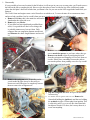
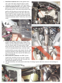
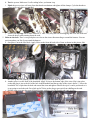
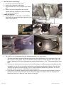
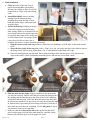
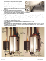
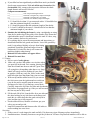
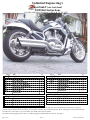
Unlimited Engineering’s
uperTankV (aka TrickTank)
#2020 Kit Instructions
Fits 2002-2006 Harley Davidson© VRSCA, B, D*, SE, SE2*
Item #
Desc
2020 SuperTankV Kit
VR Tank
2010
VR Tank Strap
2011
Heat reflective barrier
2015
2020HDW VR Fuel Tank Hardware
2025
VR Ignition Relocation Kit
2026
Rivet in Skid Kit
00002
UE Stickers
Instructions
2026 Rivet in Skid Kit
2012
Skid
3/16" SS rivets
#11 Drill Bit
Instructions
qty
1
1
1
1
1
1
1
1
1
5
1
1
Item #
Desc
qty
2025 VR Ignition Relocation Kit
Ign bracket
2035
Extension wires
2016
Extended Seat Release Cable
2017
M6x15 SHCS
M6 Flat Washer
Key Rings
Instructions
2020HDW VR Fuel Tank Hardware
Egg of Silly Putty
M10x15 SHFH
2"x1" Scotch Bright
3/4"x6" Velcro
1
1
1
1
1
2
1
1
2
1
1
*The 2006 VRSCD stock right passenger footpeg bracket interferes with the tank where the bracket attaches to the frame. If using an
aftermarket pipe that doesn’t use the hanger, it is possible to switch to the A model peg mounts. We are working on a replacement mount for
stock D’s, but it’s not ready yet. If you need this you should wait to buy the tank kit.
The 2006 Screaming Eagle needs to have it’s saddle bag support machined down a little bit. See page 9.
Page 1 of 16
Rev 3.7
©2007 Unlimited, Inc.
Welcome and thank you for purchasing our fuel tank kit. We hope you will greatly enjoy the additional range and peace
of mind that 5 gallons of fuel brings. The installation isn’t particularly difficult, but there are a number of steps that
need to be performed and should not be missed. Please take your time, read the instructions and be conscientious at all
times.
Please understand that there is absolutely no way these instructions can be all inclusive and know every mistake
that can be thought of and warn you in advance. You must have the skills and aptitude to do modifications and an
installation of this nature professionally, it’s the fuel system after all – you are potentially playing with fire.
Please do NOT attempt this project if you don’t have the necessary skills & equipment to do a safe job.
You’ll find a list of tools used at the end of the instructions.
Alright? Enough doom & gloom, let’s get to work on getting your VR to hold 5 gallons of gas so you can go 200 miles
like all your buddies.
1.
2.
3.
4.
5.
6.
7.
8.
a.
10.
11.
12.
13.
14.
Summery & Table of Contents
Disassembly .......................................................................................................................................................... 3
Skid Plate installation, bending the stock skid flat and adding our extension ................................................... 4,5
Preparing the frame. .......................................................................................................................................... 5,6
Relocate Ignition, if applicable for your model. ................................................................................................ 6,7
Relocate Main Ground Strap. ............................................................................................................................... 9
Saddle bag supports. ............................................................................................................................................. 9
Tank installation.................................................................................................................................................. 10
Fuel pump and sending unit removal from stock tank.........................................................................................11
Modifying the fuel pump height and improving the gauge accuracy ..................................................................11
Install Pump & Sending unit............................................................................................................................... 12
Seat clearance...................................................................................................................................................... 13
Mudflap modifications. ...................................................................................................................................... 14
Reassembly .................................................................................................................................................... 14,15
Testing................................................................................................................................................................. 15
Note: Due to the multiple applications we use to write the instructions the TOC is not automated, the page numbers are a manual process. If
they get out of sync, let us know and we’ll update them.
Page 2 of 16
Rev 3.7
©2007 Unlimited, Inc.
1. Disassembly
It’s not possible to have one location for the lift where it will not get in your way at some point, you’ll need to move
the bike on the lift to complete the job. However, the best place to start is with one leg of the jack directly under
where the skid plate’s bend will touch when you flatten it out. So you can use the lift to support the bend while you
flatten it.
The Vrod’s frame and engine create a nice flat surface on which to sit, I’ve moved mine all over numerous times
and never had a problem. Just be careful when you move it and you shouldn’t have a problem either.
a. Remove Maxi fuse, this is the main fuse and can be
found under the right side cover.
b. Remove the rear shocks.
c. If your bike has been significantly modified from
stock, it’s a good idea to check a few things, this
is probably unnecessary, but can’t hurt. Fully
compress the rear suspension (bottom out the tire)
and Measure the shock length distance and record
L1____________
d. Remove rear wheel, pulley, belt covers and belt, be
sure to mark the spacers so you know where they go.
e. Remove rear brake caliper by unclipping the hose
from the swingarm and wrapping it in a towel, then set
it aside. Either place something between the pads to
prevent the pistons from pushing out or be very careful
you don’t press the brake pedal.
f. Remove the swingarm axle. Depending on the
year & model & pipes it may be necessary to
loosen one end of the pipes or completely remove
them to remove the swingarm axle.
g. Slip the swingarm axle back in to prevent the motor
from moving.
h. For models with the ignition under the seat: Remove the
10mm bolt holding the ignition in and the two holding
the seatlatch in place. Extract plug from ignition. This
is a bit tricky and I’ve yet to see one where that little
latch doesn’t break. If it does, don’t worry about it, it
wont’ hurt anything.
Page 3 of 16
Rev 3.7
©2007 Unlimited, Inc.
i. Pry off the ignition extension and discard. This is
the thing up on top of the ignition where the bolt
goes thru. If you look on the back you can see about
an inch down the split line and the edge of the
double sided sticky tape.
j. Remove the mud flap.
k. Remove airbox top (clips) and unplug sensor.
l. Remove airbox bottom (venturi screws and hose
clamps)
m. For models with a siren: Remove the siren.
n. For models with saddlebag supports: Remove the
supports and saddlebags if necessary. NOTE: if you
have access to a right angle drill, you need not
remove them, you can countersink them right in place.
This can be a time saver. ‘06SE2s will need to remove
them for modification.
o. Disconnect the electrical connection at the fuel sending
unit.
p. Depressurize fuel system by relieving the pressure at
the fuel tap. Use a towel to catch any spillage.
q. Disconnect fuel lines by pressing in on the blue tabs and pulling the line off the motor first, then the sending
unit (it’s easier this way.) Use a towel to catch any spillage. Take the fuel line off both ends. If you have an older
model (’02-’04) now is a great time to replace them with the updated lines HD#s 61504-07 & 61505-07.
r. Remove the tank strap.
s. Remove the tank, block the open ports and set aside.
t. On California bikes equipped with evaporative canister, remove the canister.
2. Skid Plate installation, the stock sheetmetal is soft and moves easily so you don’t need much force to move the
material. You’ll probably also find the stocker isn’t at all flat and really needs to be ‘massaged’ anyway.
a. Bend the stock skid plate flat.
b. Using a spot weld cutter or small grinder remove the
evaporative canister bracket from the underside of
the skid plate. Be careful of any spilled fuel, you will
be making sparks and don’t want to start a fire.
c. Position the new skid plate and clamp in place.
Page 4 of 16
Rev 3.7
©2007 Unlimited, Inc.
d. Using the holes in the new skid plate as a guide for drilling 3/16” holes for the rivets.
e. Install the rivets.
f. Recheck the whole skid to ensure it’s not going to push up on the tank anywhere. If it’s not good and flat
you may need to adjust it a little more, a deadblow
hammer works great for this.
3. Preparing the frame. While your new tank will fit right
in without any further modifications, it is possible that the
space you are putting it into has some very rough sharp
points. Common sense says that you don’t want these sharp pokey things ever touching or rubbing your new tank
that’s holding a flammable liquid. Later (‘04+) frame years were greatly improved in this area, but the early models
(’02-’03) can be a little, shall we say: ‘rough’.
I like to think of this of this part of the installation like making a nice smooth bed for the new tank to lie in. That
means cleaning up the surface of the frame from anything that might be sticking into the tank area. The tank will
change size over its life. It grows initially from exposure to fuel and will constantly change in size with temperature
due to the very nature of plastic. While the tank may not contact a protrusion now, it may in time. So try to make
anything pokey or sharp in this area very smooth. A small hand grinder or Dremel® tool works well for this
process.
a. The frame may have welds protruding into the fuel tank area which should be smoothed out. Take a
straightedge and run it across the junctions. If it’s sticking out, smooth it down. That goober at the top inside
seems to be pretty consistent in all the bikes and needs to go. There’s also one where the main tubes come into
the swingarm castings that needs help.
b. The frame may have weld splatter out in the middle of the tube which may protrude into the fuel tank area
which needs to be smoothed out.
c. Clean up any other foreign objects which may be sticking into
the area where the new tank will lay. You’ll want it very smooth
there.
d. Feel around in the fuel line channel for anything sharp or rough
and smooth if necessary.
e. VRSCD models left footpeg
boss may stick in. You need
to trim this flush so it will
not push on the tank.
Page 5 of 16
Rev 3.7
©2007 Unlimited, Inc.
f. There’s also a spot at the right rear corner where
the softening of a sharp edge seems like it would be
a good idea. Stick the tank in, mark what’s covered,
pull the tank back out and radius that corner a little
where it’s close to the tank.
g. Now would also be a good time to install the tank
strap and check the length of the bolts just to be
sure they won’t poke the tank. There should be
plenty of room, but you never know if someone
substituted a bolt that’s too long and this should be
checked. Take the strap back off.
h. Using touchup paint, paint any spots where you’ve
broken the painted surface. While you are at it you
can also touchup where the stock tank chaffed.
4. Relocate Ignition, (if applicable for your model.)
a. Take the ignition over to a clean surface where tiny
parts cannot fall to the floor and get lost. Remove
the 3x T10 Torx screws. Be very careful here,
there’s 2 springs and 2 pads in there you don’t want
to lose. It will also come apart much further and
you really don’t want to do that, leave the ignition
barrel alone. Carefully extract the stock seat latch
cable. Unscrew the spring from the stock cable and
screw it back on the extended cable.
Install the extended cable in the switch. Make
sure the springs and pads are still in place and put
the ignition back together w/ the 3x torx screws.
Reinstall the screws and TEST it. Make sure the ignition
works properly.
The time to find out you didn’t get the cable in there
right isn’t when it’s all zip tied in place.
b. Remove the two screws from the valve cover where the
ignition bracket will attach.
Page 6 of 16
Rev 3.7
©2007 Unlimited, Inc.
c. Install the extension wires on the ignition in the
same color code order using the plug as a guide.
Large Red, red w/ black stripe, red w/ grey stripe.
d. Attach the ignition bracket to the ignition, slip the
ignition wires into the slot in the bracket and put
the ignition in place. Notice how the position of the
ignition will keep the wires in the slot, make sure
they aren’t pinched. Then use the M6 washer and
M6x15 SHCS to hold it together. Must use the M6
washer under the screw head or the bolt will hit the
seatlatch mechanism inside. Test the key to be sure it
works.
e. Loosen the clamp holding the two radiator pipes
together and the clamp on the upper chrome cover.
Fish the seat latch cable between the two pipes and
over the chrome shield. You may need to wiggle
things around a bit, but they’ll fit. Put the valve cover
screws in and tighten them down, work the cables
around until they run nice and straight. Run the cable
along the underside of the radiator pipe up over the
top of the frame and down into the fuel tank area as
shown in the photos.
f. Disassemble the seatlatch with a T15 Torx bit.
Again being careful not to lose any part. Transfer
the latch to the extended cable and reassemble the
seatlatch and reinstall to the frame.
g. The cable should lay nice and smooth in the frame. Fit things in place and test to ensure it’s all working as it
should.
Page 7 of 16
Rev 3.7
©2007 Unlimited, Inc.
h. Test the system. Make sure it’s all working before you button it up.
i. Ziptie the power wires well away from the throttle mechanism and tighten all the clamps. Cycle the throttle to
ensure wires can’t hit or get pinched.
j. Switch your keyrings out for these small Ø1/2” ones. They keep the fob from flapping and it sits still about like
shown in the pic when running down the road.
5. Relocate the siren. There’s two good places to relocate the siren without needing to extend the harness. You can
put it anywhere you like if you extend the harness.
a. One place is near the fuse block. Apply Velcro to the frame & back side of siren as shown in this picture, fish
the wires up thru the opening, stick it down and put the fuse block back in place.
b. Another place is on the front of the heatshield. Apply Velcro to the bottom edge of the siren. Slip it into place
so that the plug is just to the left of the hole in the heatshield and the top edge of the siren is about ½” above the
heatshield. Put a ziptie thru the hole and around the siren and tighten. Ensure the zip tie’s end is positioned so it
is not going to touch the tank. Put a little pad of Velcro on the plug to prevent it from chaffing on the tank.
c. Pull the siren wires into the upper left hand corner with the rest of the bundle and ziptie in place.
Page 8 of 16
Rev 3.7
©2007 Unlimited, Inc.
6. Relocate Main Ground Strap.
a. Loosen the connection on the frame
b. Remove the connection at the motor.
c. Reposition the wire so it lays parallel to the frame
rail.
d. Remove the nearest engine bolt and reattach.
Tighten the frame connection. Put the remaining
screw in the previous hole.
7. Saddle bag supports.
a. Using a 90° Ø3/8” Countersink, countersink the
front saddle bag support and replace the stock screw
with a countersunk one.
b. The ‘06SE is a bit of a departure from the standard and needs a few easy tweaks.
i. The inner strut/fender support/saddlebag support needs a little modification. Need to machine a flat so the
tank can pass it during install. Draw a line parallel with the ground just below the shock bolt’s stud in the
support. Machine the area below that line down until the final thickness is .200”. Then countersink the front
hole.
ii. You have two choices on the seat release. You can either change to a rubber grommet eliminating the cable
all together. Or you can use our ignition relocation kit and skip the part about the ignition wires since the
‘06SE has the ignition relocated already. Tip: the chrome and black button looks good there, It’s like $6
from HD. Chrome is from the ‘06SE, Black from the Destroyer.
iii. If you choose to continue using the plastic triangular frame covers you need to trim the fingers back a bit.
Trim them so the part that sticks back out does not and the fingers are flush to the frame. Then glue the
button in the hole so it’s flush, use clear silicone or shoe goo.
Page 9 of 16
Rev 3.7
©2007 Unlimited, Inc.
8. Tank installation.
a. Clean the inside of the tank. Turn it
upside down and shake out anything
that may have fallen in. Blow it out with
compressed air. Wipe it out with a damp
cloth.
b. Install Heat Shield, remove backing,
starting from the bottom push the
shielding down with the edge of your
hand, the slit the edges with a razor and
wrap the edges.
c. Test fit the lockring. Flashing at the top
of the tank could prevent the lockring
from seating. While we do trim this on our
end, with the nature of a manual operation
it’s possible that it may not be enough and
is worth a final check. I’m going to make
a special tool for this to ensure this is
complete, but for now, a check should be performed.
i. Snip the corners of the lock ring as shown. While this isn’t mandatory to fit the bike, it does make install
easier.
ii. Shave the lower edge of the ring with a knife – Don’t try to cut, just scrape the edge with a knife to remove
the sharp corner. You are going to put about a 30° x 1mm chamfer on the sharp outer edge.
iii. Screw the lockring down onto the tank. The lockring should go down into the groove. If it does not and
stops on the surface, check for flashing around the groove and trim any excess with a knife.
d. Slide the tank into the frame. Inspect carefully for any protrusions
you may have missed. Pull the wire that goes to the fuel pump up thru
the opening and the ones that go to the siren (if not in use) and purge
solenoid towards the back. You’ll slip them into place once the pump
& lockring are installed. If it does not go in easily do not force the tank
in, find out what’s preventing it from seating and correct. Each one of
those little groves is there for something. Use the silly putty to check
for clearance in any areas in question.
e. Make sure that the vent/overflow line at the top fits into the small
groove on the upper left side in the tank meant for it and the wiring
harnesses fit into their grooves at the upper left corner.
Page 10 of 16
Rev 3.7
©2007 Unlimited, Inc.
f. Pull the overflow line out to the side (not pinched
between engine and tank) as shown in the photo.
g. Check the clearance between the neutral sensor (under
the rear of the motor) and the tank. Should be at least
several millimeters.
h. Do NOT install tank strap yet because it’s easier to
install the sending unit and lockring if you can wiggle the
tank a bit.
9. Fuel pump and sending unit removal from stock tank.
a. Using special service tool (Kent-Moore HD-45324 or
equivalent) remove the sending unit retaining ring from the OEM tank.
b. Gently lift the factory sending unit from the OEM tank.
10. Getting the last drop is a set of steps where you ensure that the pump is reaching it’s maximum depth. This will
ensure that the rubber foot rests on the bottom of the tank and that you get all the fuel possible. On all the stock
sending units we’ve inspected the pressure line holds the pump from reaching it’s maximum depth or ever touching
the eclip due to the position of the in-line filter in the aluminum extrusion. We will loosened the screw and tap the
filter upwards to ensure that the pump reaches the maximum depth.
a. Loosen one screw on the bottom (see picture)
b. Gently tap the filter upward until the aluminum extrusion seats firmly on the e-clip.
c. Tighten the screw.
d. Test it. Hold the entire unit upright by the flange. Check that the pump assembly does go all the way down and
rests on the e-clip. Now push it up an inch or so, it should slide easily without much force, gravity should pull it
back down to it’s proper position.
Page 11 of 16
Rev 3.7
©2007 Unlimited, Inc.
11. Install Pump & Sending unit.
a. Install the o-ring. Factory spec is that the o-ring (HD refers to this as a ‘quad seal’ HD# 61498-01) should
be replaced every time. What we’ve noticed is that a used or old o-ring fits loosely on the neck of the tank. A
new o-ring will fit snugly. If it doesn’t fit snugly, replace it for sure. Harley spec is that you put small dabs of
silicone at 4 places around the neck, install o-ring and allow to tack up for 5 minutes.
b. Gently install the sending unit down into the tank and orient so that the hoses face forward. Be careful you
don’t knock the o-ring out of place. Visually inspect once fully seated to ensure the o-ring is in place.
c. Put a little lubricant on the face of the lockring which will clamp on the flange, a little on the threads and a
little on that outer edge you chamfered. This allows you to reach the torque spec more consistently and doesn’t
Page 12 of 16
Rev 3.7
try to twist the flange/sending unit as hard.
d.
Orientate the ring so the arrow points as shown
in the photo, it will then start threading immediately. Be
extremely careful you don’t cross thread it. Not only
would this cause a severe leak but would likely damage the
tank and lockring too.
e.
Once it’s going together straight, torque the lockring
to 40-45 ft-lbs.
©2007 Unlimited, Inc.
f. Reconnect the fuel lines, making sure that the blue tabs pop back
out, this will indicate that they are fully seated and locked. These
only go on one way so it’s nearly impossible to assemble wrong.
g. Reconnect the plug and overflow line.
h. Now install the tank strap and bolts to fully secure the tank. Use
blue Loctite on the bolts.
i. Using the two holes in the lower part of the guard as a guide drill
Ø3/16” holes thru the tube. Install the two 3/16” rivets.
Some notes:
A. If during your initial installation you had difficulty getting the strap
bolts started you need to figure out why. Forcing it closed could cause the
tank to bow if you use enough force. A few places we’ve identified are
1. We are seeing a number of cases where the installer has forgotten to countersink the front saddlebag support
bracket holes and install the countersunk bolts.
2. The heatshields on the frame not being properly fixtured before welding leaving a large gap between the shield
and the swingarm guard. A tap with a ball peen hammer will correct this. Tap the spot welds flat so the guards
are flush.
3. VRSCD models with the left side peg support boss sticking in may need this boss to be shaved until it’s flush
with the tube.
B. Lower belt guard may need it’s tip radiused slightly to keep it from
hitting guard/tank. Install the guard and inspect from the underneath. If it
looks like the tip will contact the tank then slightly radius that tip.
C. The new ‘belt guide’ feature is intended to keep the belt on the pulley
instead of allowing it to walk off and use the frame for the guide.
12. Seat clearance, with the top of the lines being below the frame it’s
virtually impossible that you’ll have any clearance issues between
the underside of the tank and the fuel but the tank is 3/16” taller
than stock so it deserves to be checked, particularly if you have an
aftermarket seat. DO NOT SKIP THIS STEP, it’s very important that
you ensure the seat will not chaff the fuel lines or put undue pressure
on the cap.
a. Using the silly putty rolled about 4” long lay this over the top
of the fuel lines at their connectors (the tallest part) and close
the seat. Open the seat and inspect the silly putty. If it’s been
squished to zero anywhere you need to modify the seat a little.
i. All the HD seats should fit without modification.
ii. Ultra low profile Fiberglass seats may need to have some
material removed, DO NOT HEAT FIBERGLASS pans all
you will do is make it hot, it will not get soft and bend like
the polymers will. Your experience may vary so be sure to
confirm you have clearance.
b. Also use the silly putty to check the clearance at the fuel cap.
We’ve found the HD chrome gas cap (61272-92B) is a little
shorter than the stock cap, but establishes a safe ceiling taller than
the fuel lines – and it looks cool too – MORE CHROME! Also
there are lots of flat caps to choose from on the aftermarket. My
local custom shop gave me one free – they take them off bikes
and replace them with fancy ones. There are pages of them in
catalogs to choose from.
Page 13 of 16
Rev 3.7
©2007 Unlimited, Inc.
13. Mudflap modifications. If it weren’t for the big notched area the mudflap would probably fit pretty well.
a. Put on a pair of hot mits or welding gloves and heat the area indicated with a heat gun. Feel for the stiffness of
the material frequently. As soon as you feel it give (aprox 250°F) push it into place and put the nuts on and snug
them down. Then work it again using the gloves and
work it into a nice shape. Those of you with wide tires
can also heat the ‘wings’ a bit and form them to the tire
better so you don’t have to trim. You can also form it
so it’s no longer possible to access the seatlatch – on a
stock bike any thief could have the seat up in seconds.
You can stop this completely by forming the mudflap.
Do NOT overheat, the mudflap can be destroyed with
excessive heat.
14. Reassembly
a. Reinstall swingarm & axle, lubricate with grease or anti-seize, red Loctite, ’02-’04 is 45-55 ft-lbs, for ‘05+
check the factory service manual
b. Fully compress and extend the swingarm, inspect carefully for rubbing and binding and what it’s stopping on
– shouldn’t stop on any sharp points. The swingarm should sit up against the strap and the footpeg mounts
should fit cleanly in their pockets.
c. If your bike is heavily modified from stock, fully compress the swingarm and measure the shock length
distance and record L2 below.
d. Fully extend the swingarm measure the shock length distance and record L3 below.
e. Reinstall the rear caliper. Make sure when you run the line on the underside that there’s plenty of clearance
for the tank.
f. Reinstall rear wheel, pulley and belt according to factory specifications. Don’t tighten the belt or install the
shocks yet. Lubricate axle with grease or anti-seize.
Page 14 of 16
Rev 3.7
©2007 Unlimited, Inc.
g. If your bike has been significantly modified from stock you should
check some measurements. With axle all the way forward and the
tire installed, fully compress the suspension. Measure the shock
length distance and record L4 below.
Compare measurements:
L1__________________, stock compressed length with tire.
L2__________________, TrickTank, swingarm only compressed length
L3__________________, TrickTank, swingarm only, free length
L4__________________, TrickTank, tire installed, compressed length
L2 should be less than L1 you measured earlier. L2 should be less
than the minimum length of your shocks.
L3 should be greater than the maximum length of the shocks.
L4 and L1 should be the same. L4 should also be less than the
minimum length of your shocks.
h. Simulate the belt hitting the frame by using a straightedge or string
from the far inside edge of the pulley to the outside of the frame tube
right behind the motor. It should not contact the tank. If it does, stop,
do not continue, find out why and correct.
i. If everything checks out on the measurements and inspections, go
ahead and install the belt guards and shocks. Lower belt guard may
need it’s tip radiused slightly to keep it from hitting
guard/tank. Install the guard and inspect from the
underneath. If it looks like the tip will contact the
tank then slightly radius that tip.
j. Reinstall the lower airbox and upper airbox.
k. Reinstall the maxi fuse.
15. Testing
a. Put on a pair of safety glasses
b. Make sure you have the rubber cover in place when
you pour fuel in the tank. Fair warning, pouring fuel
from the old tank into the new tank isn’t great. First
off, trying this with anything other than a very large
funnel will surely result in soaking all your work
in gasoline. AND any crud, dirt, rocks, on the stock
tank falls right down that funnel into your new tank.
c. With seat up and the rubber boot off so you can see
the fuel system, turn the ignition and run switch on
(you do not need to actually start the motorcycle)
and inspect for leaks. If you find any, correct them.
Carefully inspect the fuel lines for leaks and also that the
blue latches are popped back up, if they are still recessed
the line may not be fully seated.
d. Fill the tank full of fuel, lean the bike far to one side and
the other looking for any leak between the flange and
tank (this is a final check that the quad seal stayed in
place and the ring is fully torqued.)
e. Put the rubber boot on, latch the seat down, put your
safety gear on and go ride.
f. Inspect all connections and fasteners after 100 miles to
ensure nothing has come loose.
Servicing
1. In the event of a crash inspect the tank carefully. If it shows any signs of damage replace immediately.
2. Installation times: Normally first timers can get the job done in 4-6 hours. Experienced installers will be able to
Page 15 of 16
Rev 3.7
©2007 Unlimited, Inc.
do that in 2 hours. When providing written estimates, a provision should be included to account for stuck axles
which could greatly increase the install time and it’s even possible to force the need for new parts. Also you
should account for swingarm axle to pipe clearance, it may be necessary to remove the exhaust pipes to remove
the swingarm axle.
Tools Used:
2x4, hammer, dolly, straightedge, etc (flatten stock skid)
Safety Glasses
4.5" hand grinder (remove cannister bracket)
Lift & strap
Cordless Drill (drill holes for rivets)
4mm hex key (side cover)
Rivet gun (install skid) Warning: These rivets are very
8mm Hex key & 19mm wrench (rear shocks)
strong, if you are using a cheap rivet gun be careful or you’ll
16" straightedge (measure shock length)
break it.
2x 15/16 wrenches (remove rear wheel) '05 and later
Dremel & sanding drum (frame cleanup)
are 36mm
T10 Torx bit (ignition)
14mm wrench, socket, extension, ratchet (remove the
T15 Torx bit (seatlatch)
bolts holding the pipe to the pipe bracket)
90° Countersink (c'sink the saddle bag supports)
30mm socket & ratchet and a 12" crescent wrench
If you have a right angle drill you can c’sink the bag
(remove swingarm axle) ’05 and later is 30mm & 9/
supports while on the bike, otherwise take the supports off.
16” Hex key
Dremel & cutoff wheel (sending unit mods)
10mm socket & ratchet (stock ignition & seat latch &
Phillips screwdriver (sending unit mods)
mud flap)
Lockring tool & torque wrench
5mm Hex key (venturi & belt covers)
Heatgun (seat pan & mudflap & fuel spill boot)
14mm socket & ratchet (tank strap bolts)
Pliers, needle nose & side cutters (dealing with zip ties)
M10x1.5 tap (chase the tank strap threads)
Checklist
O-ring pushed back down on the venturi.
3.d. Checked to ensure no sharp edges where fuel lines go.
3.f. Tank strap bolt length checked to ensure that too long a bolt wasn’t used
4.i. All wires ziptied well away from the throttle linkage.
8.f. Checked for clearance at the neutral switch sensor.
10.d. Sending unit checked to ensure it achieves full depth and moves freely on the tube.
11.a. Quad seal checked good or replaced.
11.f. Lock tab on fuel lines popped back out indicating they are locked.
12.a. Clearance between seat pan and fuel lines checked. Measured clearance________
12.b. Clearance between seat pan and gas cap checked. Measured clearance________
14.e. With swingarm full extended clearance between brake line and tank checked.
14.g. For heavily modified bikes, swingarm & tire movement dimensions checked to ensure no contact.
14.h Checked that belt could not walk over and contact tank
Installer_______________________________ Date_____________
And that’s about it on the install, you are done.
Now, it’s time to get used to this new tank. Your range is quite different now and the gauge operation will be too. You
should find it much less erratic. Take some time to get used to it.
If you have any questions or problems we have 24/7/365 support on our support forum. Just click the ‘forum’ tab on the
home page. There’s a V-Rod specific forum there. You’ll find real world end users just like yourself who are eager to
help you.
It is a separate engine from the store, so while you are welcome to use the same ID, you’ll need to register on the
forums separately.
You can also contact us at [email protected] or during normal business hours at 864-962-0383
Ride Safe, have fun and thanks for purchasing from us.
Sincerely, Robin Oury, owner, Unlimited, Inc, 500 Dunwoody Drive, Simpsonville, SC 29681
Page 16 of 16
Rev 3.7
©2007 Unlimited, Inc.