1
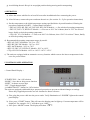
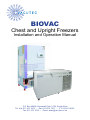
BIOVAC
Chest and Upright Freezers
Installation and Operation Manual
P.O. Box 48488, Roosevelt Park, 2129, South Africa
Tel: Jhb: 011 475 1823 • Dbn: 031 301 7617 • CT: 021 461 9607
Fax: 011 475 1819 • Email: [email protected]
1 SAFETY
WARNING
Please read this entire manual before installing and operating the unit. Any problems resulting from
the failure to comply with these instructions are the user’s sole responsibility. Any damage to the unit
caused by the user’s negligence is not covered by the warranty.
WARNING
Do not make modifications or changes to the system, including components in the unit. All
replacement parts should be factory authorized. Failure to comply will void the warranty. Vacutec shall
not be liable for any damages, including incidental and/or consequential damages.
WARNING
Please ensure proper grounding of the unit prior to use and do not connect the unit to overloaded
power lines.
WARNING
This freezer is designed for operation at extremely low temperatures where direct skin contact is
harmful. DO NOT work inside the freezer chamber without proper protection. Wear protective
clothing and eyewear at all times when working in the freezer chamber.
2 PRE-INSTALLATION
Upon delivery of the unit, please examine the exterior for physical damage while the carrier’s
representative is present. If exterior damage is visable, carefully unpack and inspect the unit and all
other accessories for damage.
If there is no exterior damage, unpack and inspect the equipment within five days of delivery. If you
find any damage, keep the packing materials and immediately report the damage to the carrier. Do
not return goods to Vacutec without prior written authorization. When submitting a claim for shipping
damage, request that the carrier inspect the shipping container and equipment.
3 INSTALLATION
a). The unit should be installed in a well ventilated area away from direct sunlight.
b). Do not install the unit adjacent to a heater or near heat-generating devices.
c). Install the unit such that there is at least 30 cm clearance from the wall to ensure proper air circulation.
This is critical for the long term reliability of the compressor. Insufficient clearance for the discharge
of heat from the compressor will reduce the cooling efficiency of the unit and may cause damage to the
compressor.
d). Ambient room temperature should be maintained below +27°C at all times. Temperatures in excess
of +32°C will significantly reduce the unit’s cooling efficiency and may result in damage to the
compressor.
e). A grounded electrical power outlet with 15A or higher is required.
f). Added Voltage regulation is recommended if the power supply is irregular and/or voltages less than
208V commonly occur.
2
g). Avoid tilting the unit. Keep it in an upright position during moving and/or transporting.
4 OPERATION
a). Allow the unit to stabilize for at least 24 hours after installation before connecting the power.
b). After 24 hours, connect the power and turn the unit on. (See section 5a - 5q for operation instructions)
c). Set the temperature to the initial temperature setting specified below by model number, following the
procedures outlined in PART 5, “Control Panel Operation”:
• DFU-AE, DFU-BE, DFC-AE, DFC-BE, DFC-84CE Models —> Set at desired operating temperature
• DFU-CE, DFC-CE, DFUD-CE Models —> First set at -20°C for 24 hours, then at -70°C for at least 7
hours, finally at desired operating temperature
• CFQ-150, 152, 156 Models —> First set at -80°C for 24 hours, then -150°C for at least 7 hours, finally
at desired operating temperature
d). Recommended operating temperature ranges by model:
• DFU-AE, DFC-AE Models: -20°C to -35°C
• DFU-BE, DFC-BE Models: -30°C to -50°C
• DFC-84CE Models: -30°C to -70°C
• DFU-CE, DFC-CE, DFUD-CE Models: -50°C to -80°C
• CFQ-150/152/156 Models: -80°C to -145°C/-147°C/-152°C
e). The units are equipped with an automatic recovery function which resets to the last set temperature in the
case of a power failure.
5 CONTROL PANEL OPERATION
< Control Panel Display >
“START/STOP “: On / Off selection
“MODE”: Save data or skip to next function
“SHIFT”: Advance to next digit
“INC”: Toggle through digits
“ALARM ON/OFF”: Alarm On / Off selection
The units are equipped with double-layer password protection to prevent accidental changes to settings.
Please keep supplied passwords in a safe location for future reference.
a). First, plug the power cable into the power outlet. Verify illumination of “POWER” light on the control
panel display.
b). Next, press “START” button. This will cause the display panel to light up. Current temperature will be
displayed. For example +20° C will show up as “0020”.
c). Now press “MODE” button. The display will show “PAS1”.
3
d). Press “MODE” button again which will cause the display to show “0000”. Enter the password “9013”
(please note that the password has been set at the factory ). Enter the last digit of the password “9013”
by pressing the “INC” key until “3” is displayed. Then press the “SHIFT” button to advance to the
next digit. Repeat the process for the other digits.
“0000” → “9013”
e). Now press “MODE” button again and the display will show “TEMP”.
“TENP”
f). Press “MODE” button again and set the operating temperature by using “SHIFT“ and “INC“ keys as
above. For example, a -20° C setting will require the display to show “–020” Please refer to PART 4
above (“Operation”) for appropriate temperature specifications for your model.
g). Press “MODE” button again and the display will show “AALH” (Absolute Alarm Limit High /
COB2B backup temperature).
“AALH”
h). Next press “MODE” and set the AALH or COB2 Bbackup temperature. The recommended AALH
setting is +20 to +30°C higher than the operating temperature. For example, a unit operating at -80°C
could have an AALH setting of -50°C
“–050”
i). Press “MODE” button again and the display will show “AALL” (Absolute Alarm Limit Low).
“AALL”
j). Next press “MODE” and set the AALL temperature. The recommended AALL setting is the lowest
rated temperature for that model. For example, a unit operating at -80°C could have an AALL setting
of -86°C
“–086”
k). Now turn the alarm function “On” by pressing the Alarm On / Off key. Verify “ALARM ON” light is
illuminated.
l). Press “MODE” button again and the display will show “LOC” (Lock function)
“LOC”
m). Press “”MODE” button again and the display will show “0000”
“0000”
The LOC function can be toggled On / Off by inputting the following codes
“1111” = Lock function On “0000” = Lock function Off / Release mode to reset. It is
recommended that the lock function be set to “On” to protect your program setting for the unit. Once
the LOC function is “On”, the unit will not respond to program changes or the “START/STOP”
operation button.
NOTE: It is not necessary to enable LOC during the initial start up phase.
n). Press “MODE” key again and the display will show “PAS2”
“PAS2”
PAS2 must be entered to fix your current settings. Otherwise, your settings will not be saved.
o). Press “MODE” button again and the display will show “0000”
Enter the 2nd password “9014” (please note that the password has been set at the factory)
4
p). Press “MODE” button again. You have now fixed your settings. The current temperature will be
displayed.
Programming of the various settings is now complete.
To stop the operation of the unit
If the buttons are locked, go to “LOC” mode and release lock function by entering “0000”.
Press the “MODE” key once more to display “PAS2” and enter “9014”.
Finally press “START/STOP” and disconnect power cable from the power outlet.
6 SAMPLE STORAGE
a). Allow the unit to run at the desired operating temperature for at least 3 days, intermittently checking
the temperature stability, before loading samples into the unit.
b). Load no more than 1/3 of the total capacity initially.
c). Allow the temperature to re-stabilize to the desired operating temperature for 24 hours, then load up to
another 1/3 of the total capacity.
d). Repeat the above process until fully loaded.
NOTE: Increase in storage utilization will enhance temperature stability of the unit.
WARNING
a). Do not load more than 1/3 of the total capacity of the unit at any one time
b). Do not load large volumes of liquid samples or hot water. This will increase the chamber temperature
and will cause the compressor to operate continuously for a prolonged period, potentially reducing the
life of the compressor.
c). Do not open cabinet door for more than 1 minute as chamber temperature air will escape quickly.
d). Bear in mind the unit is for preservation and not for production. The unit is not a rapidfreeze device to
be used in a production environment with frequent sample rotations.
7 MAINTENANCE
a). It is vital to check and clean the filter every 3 months (more frequently if the environment is
particularly dusty).
• Open grill and remove filter.
• Clean the filter by first shaking the dirt off filter, away from the unit. Then wash in clean water and
thoroughly dry.
• Replace filter and close grill.
b). In the case of a major problem, please contact Vacutec directly.
[email protected] (011) 475 1823
5
P.O. Box 48488, Roosevelt Park, 2129,
South Africa.
Tel: Jhb 011 475 1823
Dbn 031 301 7617
CT 021 461 9607
Fax. 011 475 1819
email: [email protected]