1
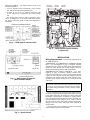
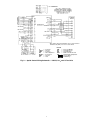
48/50HJ004-024
50TFQ004-012, 48/50TF,TM004-014
50HJQ004-016, 48/50TJ,TM016-028
Apollo Control
Installation, Operation, and
Troubleshooting Instructions
SAFETY CONSIDERATIONS
Read these instructions entirely before modifying the base
rooftop unit.
Before beginning any modification, make sure all power is
disconnected to the unit and locked out. Failure to disconnect power supply prior to servicing may result in serious
injury. All wiring must comply with applicable national
and local codes.
Installation and servicing of air-conditioning equipment can
be hazardous due to system pressure and electrical components. Only trained and qualified service personnel should
install, repair, or service air-conditioning equipment.
Untrained personnel can perform the basic maintenance
functions of replacing filters. All other operations should be
performed by trained service personnel. When working on airconditioning equipment, observe precautions in the literature,
tags and labels attached to the unit, and other safety precautions
that may apply.
Follow all safety codes. Wear safety glasses and work
gloves. Use quenching cloth for unbrazing operations. Have
fire extinguishers available for all brazing operations.
When removing panels from the unit, be careful not to
damage the roof or other surfaces with the panels.
GENERAL
The TEMP System thermostat maintains proper temperatures by controlling the amount of heated or cooled air supplied
to the area in which it is installed or the area it controls (if using
a remote room sensor).
Each thermostat is responsible for controlling the temperature conditions in its space. Each thermostat will maintain its
own independent occupied/unoccupied time schedule and heating (if applicable) and cooling set points. This allows the user
to program the TEMP System thermostat so that it will maintain different temperature ranges at different times.
TEMP System Components — The Carrier TEMP
System consists of one or more thermostats that communicate
by way of a communication bus. Each thermostat controls an
Apollo control which in turn controls the Carrier rooftop unit.
See Fig. 1.
Each thermostat can be connected to others to provide communication between thermostats. Only one thermostat per system can have a timeclock that will broadcast time to the rest of
the system. See Fig. 2.
TEMP SYSTEM THERMOSTATS — The 33CSTMT-01,
or 33CSVMT-XX (with timeclock) and 33CSTM-01 or
33CSVM-XX (without timeclock) TEMP System thermostats
(see Fig. 3) have the following features:
• controls temperature to user-defined set points
• eliminates the need for external timeclocks, manual
override timer, night low limit thermostat, battery
backup, or unit time guard
• operates with 3 system switches for supply-air fan and
the unit heating (if applicable) and cooling stages
NOTE: For 33CSVM(T)-XX thermostats, the “XX” will be
either “04,” “16,” or “32.”
The Apollo control is a relay pack which is factory wired
and mounted in the Carrier rooftop unit. The Apollo control
allows the unit to be connected to a thermostat and a communication bus. The rooftop unit can then be used as part of a
system which is controlled by devices on the communication
bus. The thermostat and communication bus wiring must be
field installed.
Do not turn on unit power until Apollo control and thermostat have been installed. Unit is shipped with loose leads
which may cause electrical shock or death.
Carrier TEMP System — The Carrier TEMP System
usually consists of more than one thermostat and can be expanded to meet whatever number of single zone systems are
required.
HVAC — Heating, Ventilation, and Air Conditioning
*Where “XX” will be “04,” “16,” or “32.”
Fig. 1 — Carrier TEMP System Components
Manufacturer reserves the right to discontinue, or change at any time, specifications or designs without notice and without incurring obligations.
PC 111
Catalog No. 534-80082
Printed in U.S.A.
Form 48/50H,T-15SI
Pg 1
8-01
Replaces: 48/50H,T-2SI
Book 1 1 1 4 4 4
Tab 1a 1b 5a 5a 6a 6b
APOLLO CONTROL — The Apollo control (see Fig. 4) has
the following features:
• serves as interface between thermostat, Carrier rooftop
unit, and any external field-supplied sensors
• powered by 24 vac/10 va; supplies thermostat with
10 vdc. This power is supplied by the Carrier rooftop
unit.
The Apollo control must be used in conjunction with a
Carrier 33CSTM(T)-01 or 33CSVM(T)-XX master thermostat. Figure 5 shows the Apollo control factory-installed in a
rooftop unit.
WIRING TO
THERMOSTAT
APOLLO
CONTROL
CONTROL
WIRING
*Where “XX” will be “04,” “16,” or “32.”
Fig. 2 — TEMP System Communication
Fig. 5 — Apollo Control Factory-Installed
In Typical Unit
INSTALLATION
Wiring Requirements — The wiring requirements for
the TEMP System are:
THERMOSTAT TO THERMOSTAT COMMUNICATION
BUS — Use field-supplied, 18 gage, 3-conductor, shielded,
stranded wire, color coded (red, black, green), plenum rated (if
required by code). Be sure wire is long enough to run from
thermostat to thermostat in daisy-chain configuration.
THERMOSTAT TO APOLLO CONTROL — Use fieldsupplied, 18 gage, 5-conductor, shielded, stranded wire,
color-coded (red, white, blue, yellow, green), plenum rated (if
required by code). Be sure wire is long enough to run from
thermostat to the Apollo control. The Apollo control is easily
accessible in the Carrier rooftop unit. It is found in the unit
control box.
Fig. 3 — TEMP System Thermostat
(With Timeclock Shown)
IMPORTANT: Do not run the thermostat communication
bus and the control wire in the same conduit for more than
5 ft. Never run wires near any cable carrying AC voltage.
For further wiring information, consult your local Carrier
distributor.
Factory-supplied power required by each Apollo control is
24 vac/10 va. Typical wiring is 18-gage thermostat wire. Power
to the Apollo control may be wired to the Carrier rooftop unit
transformer if transformer is of sufficient va capacity. Otherwise, a dedicated transformer has been factory provided. The
maximum load of a relay contact is 24 vac, 1 amp. A short in
the field wiring or Carrier rooftop unit will cause non-warranty
damage to the relay board. Test wiring before attaching to
Apollo control.
Call your local Carrier representative for more information
about wiring the Apollo control as needed.
NOTE: The indicator lights verify each mode of operation.
Fig. 4 — Apollo Control
2
Thermostat Installation — Begin the thermostat in-
AUTO. Fan Mode — The fan will energize any time the
stallation by determining where the thermostat will be located.
In most cases, this will be pre-determined by the building
plans.
Locate the thermostat on an interior wall, about 5 ft from the
ground. The thermostat should be located away from direct
sunlight, drafts, or interior heat sources which may influence
temperature readings.
The thermostat may also be mounted in a remote location
with the use of an optional remote room sensor. Refer to the
specific thermostat information for more details on thermostat
installation.
system energizes heating or cooling. The only exception is
when the thermostat controls a gas heating rooftop unit. In this
application, the thermostat will allow the rooftop unit to control
the fan during Heating mode, and the fan will run in Cooling
mode.
ON Fan Mode — The fan will operate continuously during the occupied mode. In unoccupied mode, the fan will only
operate when a system mode is energized.
AUTO. Heating Mode — When the Heat switch is set to
AUTO. position, the Apollo control will energize heating when
the heating demand is 1.5° F or greater. The second stage of
heating will energize when the demand becomes 2.0° F or
greater.
Wiring Connections
OFF Heating Mode — When the Heat switch is set to
OFF position, the Apollo control will not allow the rooftop unit
to energize heating.
Electric shock can cause injury or death. Ensure power to
the rooftop unit has been disconnected, before wiring.
AUTO. Cooling Mode — When the Cool switch is set
WIRE APOLLO CONTROL TO THERMOSTAT — Wire
each thermostat to its respective Apollo control as shown in
Fig. 6. Make wiring connections at the wiring connector board
of the thermostat.
WIRE THERMOSTAT TO COMMUNICATION BUS —
The thermostat is connected to the communication bus through
the thermostat wiring connection block. Connect the black, red,
and green wires from the communication bus to the thermostat
wiring connection block. See Fig. 6. To connect other devices
to the communication bus, refer to the application manual for
that device.
to AUTO. position, the Apollo control will energize cooling
when the cooling demand is 1.5° F or greater. The second stage
of cooling will energize when the demand becomes 2.0° F or
greater.
OFF Cooling Mode — When the Cool switch is set to
OFF position, the Apollo control will not allow the rooftop unit
to energize cooling.
Temperature Trend Staging — When the Temperature Trend Staging option has been configured at the thermostat, the thermostat tracks the temperatures at regular intervals
in each cooling or heating mode. As long as the space temperature is improving, the Apollo control will not allow the second
stage to be energized. If the space temperature stays the same
or the demand becomes greater, the second stage will energize.
Provide Power To Apollo Control — After the wiring has been completed, provide power to the Apollo control.
Once power has been provided, the Apollo control will power
the thermostat. The heating (if applicable) and/or cooling set
points will appear on the thermostat display screen. The thermostat is now ready to be programmed. If the display is blank
or blinking, recheck the wiring connections between the thermostat and Apollo control.
Heating Lockout — When the heating lockout temperature set point has been configured, and the heating lockout option has been configured to ON, the Apollo control will not allow heating to energize when the outdoor-air temperature rises
above the heating lockout set point.
OPERATION
Cooling Lockout — When the cooling lockout temperature set point has been configured, and the cooling lockout option has been configured to ON, the Apollo control will not allow cooling to energize when the outdoor-air temperature
drops below the cooling lockout set point.
There are 3 system switches which are used to control operation at the thermostat: Heat, Cool, and Fan. The Heat and
Cool switches can be set to either AUTO. or OFF position. The
Fan switch can be set to either AUTO or ON position. When
the fan is running, the FAN indicator will be shown on the thermostat display screen. When Cooling mode is energized, the
COOL indicator will be shown on the thermostat display
screen. When Heating mode is energized, the HEAT indicator
will be shown on the thermostat display screen. When the
second stage of heating or cooling is energized, a decimal point
is displayed between the heating and cooling set points.
Time-Delay Relay — The thermostat and the Apollo
control utilize a 5-minute time delay between the different
modes of operation for the rooftop unit. When a mode of operation is deenergized, another mode cannot begin for 5 minutes.
3
NOTE: Refer to Product Support Bulletin No. 93-005 for shielded wire applications when wiring the thermostat to the Apollo control and for all communication
bus wiring connections or contact your local representative.
Fig. 6 — Thermostat and Apollo Control Wiring
4
TROUBLESHOOTING
2. The thermostat is displaying the decimal point.
a. Check to see if the H2 LED is lit on the Apollo
control. If it is not lit, replace the Apollo control.
b. The LED is lit, but second stage is not energized.
Check the voltage across the H2 relay contact. If it
reads 24 vac, replace the relay board. If it reads 0 to
2 vac, check the H2 contactor and the unit transformer.
See Fig. 7-10 for Apollo factory, control, and system wiring.
Blank Display or Blinking Display at the
Thermostat
1. Check to ensure there is at least 20.5 vac across the 2 terminals labelled 24 vac. If there is not at least 20.5 vac, check
the unit transformer which is powering the Apollo control.
2. If an ac voltage between 20.5 and 30 vac is read, check for
10 vdc between the terminals labelled WHT and RED. If
there is 0 vdc between the terminals, replace the Apollo
control. If a value between 1 and 10 vdc is read, check the
wiring between the thermostat and the Apollo control.
3. If the thermostat display is blinking on and off, this is an
indication that there is a communication problem between the thermostat and the Apollo control. The thermostat and the Apollo control communicate on the blue and
yellow wires. If either one is shorted, open, or crossed, it
will cause the thermostat display to blink.
To check the wiring between the thermostat and the Apollo
control:
1. Remove the thermostat and connector board.
2. Wire the connector board to the Apollo control with a
short piece of field-supplied 5-conductor cable.
3. Plug the thermostat into the connector board.
a. If thermostat powers up, there is a wiring problem.
Find the open or shorted wire, or replace the wiring
between the thermostat and the Apollo control.
b. If the thermostat does not power up, try another
thermostat. If the new thermostat powers up,
replace the off thermostat. If the new thermostat
will not power up, replace the Apollo control.
The Control Will Not Energize Cooling
1. The thermostat is not displaying the cool indicator.
a. Check the cooling lockout temperature set point
and options to make sure the outdoor-air temperature is not locking out Cooling mode.
b. Ensure that a sensor in the system is not reading
below the cooling low limit temperature. If a supply air sensor or a direct expansion (DX) coil sensor is not connected to the relay pack, turn off High
and Low Limits at the thermostat.
c. Check the Cool switch and make sure it is in the
AUTO. position.
2. The thermostat is displaying the cool indicator.
a. Check to see if the C1 LED is lit on the Apollo control. If it is not, replace the Apollo control. If the C1
LED is lit on the Apollo control, check the voltage
across the C1 relay contact. If it reads 24 vac, replace
the Apollo control. If it reads 0 to 2 vac, check the C1
contactor and the unit transformer.
The Control Will Not Energize Second Stage
Cooling
1. The thermostat is not displaying the second stage indicator. A decimal point on the thermostat display screen is the
indication that the thermostat is asking for second stage.
a. Check to see if the space demand is equal to or
greater than 2° F. The control must see a 2° F
demand before it will call for second stage.
b. Check the Temperature Trend Staging option. If
this option is configured to “on” and space conditions are improving, the control will not energize
the second stage.
2. The thermostat is displaying the decimal point.
a. Check to see if the C2 LED is lit on the Apollo
control. If it is not lit, replace the Apollo control.
b. The LED is lit, but second stage is not energized.
Check the voltage across the C2 relay contact. If it
reads 24 vac, replace the relay board. If it reads 0
to 2 vac, check the C2 contactor and the unit
transformer.
The Control Will Not Energize Heating
1. The thermostat is not displaying the heat indicator:
a. Check the heating lockout temperature set point
and options to make sure the outdoor-air temperature is locking out Heating mode.
b. Ensure that a sensor in the system is not reading
above the heating high limit temperature. If a supply air sensor or a direct expansion (DX) coil sensor is not connected to the Apollo control, turn off
the High and Low Limits option at the thermostat.
c. Check the Heat switch and make sure it is in the
AUTO. position.
2. The thermostat is displaying the heat indicator.
a. Check to see if the H1 LED (light-emitting diode)
is lit on the Apollo control. If it is not, replace the
Apollo control. If the H1 LED is lit on the Apollo
control, check the voltage across the H1 relay contact. If it reads 24 vac, replace the Apollo control.
If it reads 0 to 2 vac, check the H1 contactor and
the unit transformer.
The Control Will Not Energize The Fan
1. The fan indicator is not lit on the thermostat.
a. The Fan switch is in the AUTO. position and the
control is not in a mode (HEAT or COOL
position).
b. The fan switch is in the ON position but the thermostat is in setback and has no mode.
c. The thermostat has just received power or has just
reset and is going through its initialization process.
2. The fan indicator is lit on the thermostat.
a. Check the fan LED on the Apollo control. If it is
not lit, replace the Apollo control.
b. If the fan LED is lit, check the voltage across the
fan relay contact. If it reads 24-vac, replace the
relay board. If it reads 0 to 2 vac, check the fan
contactor and the unit transformer.
The Control Will Not Energize Second Stage
Heating
1. The thermostat is not displaying the second stage indicator. A decimal point on the thermostat display screen is the
indication that the thermostat is asking for second stage.
a. Check to see if the space demand is equal to or
greater than 2° F. The control must see a 2° F
demand before it will call for second stage.
b. Check the Temperature Trend Staging option. If
this option is configured to “on” and space conditions are improving, the control will not energize
the second stage.
5
LEGEND
COM
— Communication
ECONO — Economizer
NC
— Normally Closed
Fig. 7 — Factory-Supplied Wiring to Rooftop Unit and Apollo Control
*Filter status switch and humidity sensor cannot function
simultaneously. Only one sensor can be wired.
LEGEND
C
CHAS
COM
DX
ECON
GND
HT
—
—
—
—
—
—
—
Contactor
Ground
Common
Direct Expansion
Economizer
Ground
Heat
IAQ
NC
NO
OAT
SAT
—
—
—
—
—
Indoor Air Quality
Normally Closed
Normally Open
Outdoor-Air Thermostat
Saturated-Air Temperature
Factory Wiring
Field Wiring
Fig. 8 — Apollo Control Wiring Schematic — 48/50HJ, 3 to 20 Ton Units;
48/50TF,TM, 3 to 12-1/2 Ton Units; 48/50TJ,TM, 15 to 25 Ton Units; 50HJQ/TFQ, 3 to 10 Ton Units
6
*Filter status switch and humidity sensor cannot function
simultaneously. Only one sensor can be wired.
LEGEND
C
CHAS
COM
DX
ECON
GND
HT
—
—
—
—
—
—
—
Contactor
Ground
Common
Direct Expansion
Economizer
Ground
Heat
IAQ
NC
NO
OAT
SAT
—
—
—
—
—
Indoor Air Quality
Normally Closed
Normally Open
Outdoor-Air Thermostat
Saturated-Air Temperature
Factory Wiring
Field Wiring
Fig. 9 — Apollo Control Wiring Schematic — 50HJQ, 121/2 and 15 Ton Units
7
Copyright 2001 Carrier Corporation
Manufacturer reserves the right to discontinue, or change at any time, specifications or designs without notice and without incurring obligations.
PC 111
Catalog No. 534-80082
Printed in U.S.A.
Form 48/50H,T-15SI
Pg 8
8-01
Replaces: 48/50H,T-2SI
Book 1 1 1 4 4 4
Tab 1a 1b 5a 5a 6a 6b
GRN
BLK
GRN
BLK
87654321
BLK
RED
BLK
RED
GRN
#11
#10
#10
#11
OAT
SAT
DX
FAN STATUS
WHT
RED
BLU
YEL
GRN
IAQ STATUS†
NC
COM
NO
1
2
3
4
5
6
7
8
9
10
11
12
13
14
15
16
17
1
2
COOL
3
4
HEAT
13
12
11
10
9
8
7
FAN
RV
6
5
JUMPERS
4
SINGLE ZONE
3
RELAY PACK
2
WITH AUXILARY
1
RELAY
SINGLE ZONE RELAY PACK CIRCUIT BOARD
ALARM
RELAY
CONTACTS
+ 2-10VDC
- SIG COM (J5-3)
+ 4-20mA (J5-2)
FAN
HEAT 2
HEAT 1 NC
HEAT 1
HEAT/FAN COM
COOL 2
COOL 1
COOL COM
R
24 VAC/10 VA
C
GROUND
AUXILIARY
RELAY**
DM
VIO
PNK
TAN
VIO
WHT
RED
DAT
EC
ACCESSORY
ONLY
OAT
LEGEND
Carbon Dioxide
Common
Discharge Air Thermistor
Damper Motor
Direct Expansion Coil Sensor
Enthalpy Control
Heating, Ventilation, and Air Conditioning
Indoor-Air Quality
Normally Closed
Outdoor-Air Thermostat
Reversing Valve
Supply-Air Temperature Sensor
Temperature
Transformer (Field Supplied)
Carrier TEMP System
Variable Volume/Variable Temperature
Field-Supplied Wiring
LED
COM
DAT
COM
REM POT
COM
CO2 —
COM —
DAT —
DM —
DX
—
EC
—
HVAC —
IAQ —
NC
—
OAT —
RV
—
SAT —
TEMP —
TRAN —
VTS —
VVT® —
AO
COM
Y1
Y2
G
B1
TO CARRIER
HVAC UNIT
FIELD SUPPLIED
WIRING
YEL
WHT
BLK
CO2 COM
CO2+
OAT
COM
OAH
+15V
CLG1
RAT
CLG2
COM
CONTROLLER
RAH
+15V
24 VAC
24 COM
GND
Fig. 10 — Apollo Wiring as Part of an Indoor-Air Quality System
*Filter status switch and humidity sensor cannot function simultaneously. Only one sensor can be wired.
†Such as a CO2 sensor.
**Set auxiliary option to “2” — IAQ Control per VTS or VVT Installation Instructions.
NOTE: Sensors are field-supplied and wired.
FILTER
STATUS
HUMIDITY
SENSOR
2 1
INDOOR AIR QUALITY (CO2) SENSOR
(33ZCSENCO2) TYPICAL WIRING DIAGRAM
H G 24 VAC
OR
+ - 24 VDC
ADDITIONAL SENSORS*
TSP01
TERMINAL
NUMBER
WHT #1
RED #2
REMOTE ROOM
TEMP. SENSOR
NETWORK
GROUND
24 V
TRAN
24 VAC
20 VA
(FIELD
SUPPLIED)
RED
BRN
GRN
BLU
PNK
ECONOMI$ER OPTION/ACCESSORY