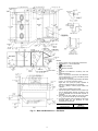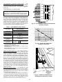
1
50HJQ014,016
Single-Package Rooftop
Heat Pump Units
Installation, Start-Up
and Service Instructions
CONTENTS
Page
SAFETY CONSIDERATIONS . . . . . . . . . . . . . . . . . . . . . . 1
INSTALLATION . . . . . . . . . . . . . . . . . . . . . . . . . . . . . . . . 1-24
Step 1 — Provide Unit Support . . . . . . . . . . . . . . . . . . . 1
• ROOF CURB
• ALTERNATE UNIT SUPPORT
Step 2 — Rig and Place Unit . . . . . . . . . . . . . . . . . . . . . 1
• POSITIONING
• ROOF MOUNT
Step 3 — Field Fabricate Ductwork . . . . . . . . . . . . . . . 3
Step 4 — Make Unit Duct Connections . . . . . . . . . . . 7
Step 5 — Trap Condensate Drain . . . . . . . . . . . . . . . . . 7
Step 6 — Make Electrical Connections . . . . . . . . . . . 7
• FIELD POWER SUPPLY
• FIELD CONTROL WIRING
• OPTIONAL NON-FUSED DISCONNECT
• OPTIONAL CONVENIENCE OUTLET
Step 7 — Make Outdoor-Air Inlet Adjustments . . 10
• MANUAL OUTDOOR-AIR DAMPER
Step 8 — Install Outdoor-Air Hood . . . . . . . . . . . . . . 10
Step 9 — Install All Accessories. . . . . . . . . . . . . . . . . 10
• MOTORMASTER® I CONTROL INSTALLATION
Step 10 — Adjust Factory-Installed Options . . . . . 12
• PREMIERLINK™ CONTROL
• ENTHALPY SWITCH/RECEIVER
• OUTDOOR ENTHALPY CONTROL
• DIFFERENTIAL ENTHALPY CONTROL
• ENTHALPY SENSORS AND CONTROL
• OPTIONAL ECONOMI$ERIV AND ECONOMI$ER2
• ECONOMI$ERIV STANDARD SENSORS
• ECONOMI$ERIV CONTROL MODES
Step 11 — Set Defrost Cycle . . . . . . . . . . . . . . . . . . . . 24
START-UP . . . . . . . . . . . . . . . . . . . . . . . . . . . . . . . . . . . . 24-31
SERVICE . . . . . . . . . . . . . . . . . . . . . . . . . . . . . . . . . . . . . 31-37
TROUBLESHOOTING. . . . . . . . . . . . . . . . . . . . . . . . . 38-43
INDEX . . . . . . . . . . . . . . . . . . . . . . . . . . . . . . . . . . . . . . . . . . . 44
START-UP CHECKLIST . . . . . . . . . . . . . . . . . . . . . . . . CL-1
SAFETY CONSIDERATIONS
Installation and servicing of air-conditioning equipment can
be hazardous due to system pressure and electrical components. Only trained and qualified service personnel should
install, repair, or service air-conditioning equipment.
Untrained personnel can perform basic maintenance functions of cleaning coils and filters and replacing filters. All other
operations should be performed by trained service personnel.
When working on air-conditioning equipment, observe precautions in the literature, tags and labels attached to the unit, and
other safety precautions that may apply.
Follow all safety codes. Wear safety glasses and work
gloves. Use quenching cloth for unbrazing operations. Have
fire extinguisher available for all brazing operations.
Before performing service or maintenance operations on
unit, turn off main power switch to unit. Electrical shock
could cause personal injury.
INSTALLATION
IMPORTANT: Units have high ambient operating limits. If
limits are exceeded, the unit will automatically lock the
compressor out of operation. Manual reset will be required
to restart the compressor.
Step 1 — Provide Unit Support
ROOF CURB — Assemble and install accessory roof curb in
accordance with instructions shipped with the curb. Accessory
roof curb and information required to field fabricate a roof curb
are shown in Fig. 1 and 2. Install insulation, cant strips, roofing,
and counter flashing as shown. Ductwork can be secured to
roof curb before unit is set in place. Horizontal adapter installation is shown in Fig. 2.
IMPORTANT: The gasketing of the unit to the roof curb is
critical for watertight seal. Install gasket supplied with the
roof curb as shown in Fig. 1. Improperly applied gasket can
result in air leaks and poor unit performance.
Curb should be level. This is necessary to permit unit drain
to function properly. Unit leveling tolerances is ± 1/16 in. per
linear ft in any direction. Refer to Accessory Roof Curb Installation Instructions for additional information as required.
ALTERNATE UNIT SUPPORT — When the curb cannot be
used, support unit with sleepers using unit curb support area. If
sleepers cannot be used, support long sides of unit with a minimum of 3 equally spaced 4-in. x 4-in. pads on each side.
Step 2 — Rig and Place Unit — Inspect unit for transportation damage. File any claim with transportation agency.
Keep unit upright, and do not drop. Use spreader bars over unit
to prevent sling or cable damage. Rollers may be used to move
unit across a roof. Level by using unit frame as a reference;
leveling tolerance is ± 1/16 in. per linear ft in any direction.
See Fig. 1 for additional leveling tolerance information. Unit
weight is shown in Table 1.
Four lifting holes are provided in ends of unit base rails as
shown in Fig. 3. Refer to rigging instructions on unit.
Manufacturer reserves the right to discontinue, or change at any time, specifications or designs without notice and without incurring obligations.
Catalog No. 535-00127
Printed in U.S.A.
Form 50HJQ-15SI
Pg 1
3-06
Replaces: 50HJQ-8SI
Book 1 4
Tab 5a 5a
2
CURB
HEIGHT
1′-2″ (305)
2′-0″ (610)
2′-0″ (610)
CRRFCURB010A00
CRRFCURB011A00
CRRFCURB012A00
PKG. NO. REF.
Standard Curb 14″ High
Standard Curb for Units
Requiring High Installation
Side Supply and Return
Curb for High Installation
DESCRIPTION
Fig. 1 — Roof Curb Details
Direction of airflow.
ALL
UNIT
in.
.45
Deg.
.28
A
.28
Deg.
B
DIMENSIONS* (degrees and inches)
.43
in.
5. Roof curb: 16 ga. (VA03-56) stl.
6. A 90 degree elbow must be installed on the supply ductwork
below the unit discharge for units equipped with electric heaters.
7. To prevent the hazard of stagnant water build-up in the drain pan of the
indoor section, unit can only be pitched as shown.
4.
NOTES:
1. Roof curb accessory is shipped disassembled.
2. Insulated panels: 1″ thick neoprene coated 11/2 lb density.
3. Dimensions in ( ) are in millimeters.
FULLY INSULATED
SUPPLY PLENUM
1" INSULATION
1 1/2 # DENSITY,
STICK PINNED & GLUED
2" X 1/4
SUPPORT TYP.
STITCH WELDED
3 1/2"
14 3/4"
23"
6"
12" WIDE STANDING
SEAM PANELS
NOTE: CRRFCURB013A00 is a fully factory preassembled horizontal
adapter and includes an insulated transition duct. The pressure drop
through the adapter curb is negligible.
For horizontal return applications: The power exhaust and barometric
relief dampers must be installed in the return air duct.
ACCESSORY
PACKAGE NO.
CURB
HEIGHT
1′-11″
(584)
CRRFCURB013A00
DESCRIPTION
Pre-Assembled, Horizontal
Adapter Roof Curb
Fig. 2 — Horizontal Supply/Return Curb and Horizontal Adapter Details
POSITIONING — Provide clearance around and above unit
for airflow, safety, and service access (Fig. 4 and 5).
Do not install unit in an indoor location. Do not locate air inlets near exhaust vents or other sources of contaminated air.
Although unit is weatherproof, guard against water from
higher level runoff and overhangs.
ROOF MOUNT — Check building codes for weight distribution requirements.
Step 3 — Field Fabricate Ductwork — Secure all
ducts to building structure. Use flexible duct connectors between unit and ducts as required. Insulate and weatherproof all
external ductwork, joints, and roof openings with counter
flashing and mastic in accordance with applicable codes.
Ducts passing through an unconditioned space must be insulated and covered with a vapor barrier.
The 50HJQ units with electric heat require a 1-in. clearance
for the first 24 in. of ductwork.
Outlet grilles must not lie directly below unit discharge.
NOTE: A 90-degree elbow must be provided in the ductwork
to comply with UL (Underwriters Laboratories) codes for use
with electric heat.
MAXIMUM SHIPPING WEIGHT
lb
kg
1895
860
2205
1000
UNIT 50HJQ
014
016
DIMENSION A
UNIT 50HJQ
014
016
ft-in.
3-1
3-6
mm
948
1059
NOTES:
1. Dimensions in ( ) are in millimeters.
2. Refer to Table 1 for unit operating weights.
3. Remove boards at ends of unit and runners prior to rigging.
4. Rig by inserting hooks into unit base rails as shown. Use corner post
from packaging to protect coil from damage. Use bumper boards for
spreader bars.
5. Weights do not include optional economizer. See Table 1 for economizer
weight.
6. Weights given are for aluminum indoor coil plate fins and copper outdoor coil plate fins. Weights of other metal combinations are listed in
Table 1.
All panels must be in place when rigging.
Fig. 3 — Rigging Details
3
Table 1 — Physical Data
UNIT SIZE 50HJQ
NOMINAL CAPACITY (tons)
OPERATING WT (lb)
Al/Al*
Al/Al Coated*
Unit Al/Cu*
Cu/Cu*
Electric Heat
Economizer
Roof Curb†
COMPRESSOR
Type (Number)
Cylinders
Oil Change (oz.) (each circuit)
REFRIGERANT TYPE
Charge (lb)
System 1
System 2
OUTDOOR COIL
Rows
Fins/in.
Total Face Area (sq ft)
OUTDOOR FAN
Nominal Cfm
Number...Diameter (in.)
Motor Hp (1075 rpm)
Watts Input (Total)
INDOOR COIL
Expansion Device
Rows
Fins/in.
Total Face Area (sq ft)
INDOOR FAN
Quantity...Size (in.)
Nominal Cfm
Fan Rpm Range
Maximum Allowable Rpm
Motor Pulley Pitch Diameter (in.)
Fan Pulley Pitch Diameter (in.)
Belt, Quantity...Type...Length (in.)
Pulley Center Line Distance (in.)
Speed Change Per Turn (rpm)
Pulley Maximum Full Turns
Factory Pulley Turns Setting
Factory Speed Setting (rpm)
Fan Shaft Diameter (in.)
Motor Hp (Service Factor)
Motor Frame Size
Motor Efficiency
HIGH-PRESSURE SWITCH
Cutout (psig)
Reset (psig)
LOW-PRESSURE/LOSS-OF-CHARGE SWITCH
Cutout (psig)
Reset (psig)
AIR INLET SCREENS
014
208/230, 460 V
575 V
016
13
15
1615
1615
1745
1815
65
90
200
1925
1925
2075
2165
65
90
200
Semi-Hermetic
06D-328 (1)
6
115
06D-818 (2)
4
88
R-22
26.0
16.5
—
16.5
3/ in., Internally Grooved Copper Tubes, Aluminum or Copper Lanced Fins
8
3
3
15
15
21.7
21.7
Propeller Type, Direct Drive
9,000
9,000
3...22
3...22
1/
1/
2
2
1090
1090
3/ in., Internally Grooved Copper Tubes, Aluminum or Copper Lanced Fins, Face Split
8
Fixed Orifice
3
3
15
15
17.5
17.5
Centrifugal, Adjustable Pitch Belt Drive
2...10 x 10
2...10 x 10
2...12 x 12
5000
5000
6000
862-1132
1201-1462
799-1010
1550
1550
1550
3.1/4.1
4.3/5.3
3.7/4.7
6.0
6.4
11.4
1...BX...42
1...B...45
1...BX...46
13.5-15.5
13.5-15.5
13.3-14.8
54
52
42
6**
5
6**
1
3
3
3 /2
1024
1279
926
3
3
7
1 /16
1 /16
1 /16
3.7 (1.15)
3.0 (1.15)
5.0 (1.15)
56H
56H
184T
0.84
0.84
0.84
426
320
7
22
Cleanable
2...20 x 25 x 1
1...20 x 20 x 1
10% Efficient — 2-in. Throwaway Fiberglass
4...20 x 20 x 2
4...16 x 20 x 2
Economizer, Quantity...Size (in.)
RETURN-AIR FILTERS (TYPE)
Quantity...Size (in.)
DEFROST THERMOSTAT
Defrost Time
Closes (F)
Opens (F)
30 min (Adjustable to 50 or 90 min)
28
65
LEGEND
Al — Aluminum
Cu — Copper
*Indoor coil fin material/outdoor coil fin material.
†Weight of 14 in. roof curb.
**Pulley cannot be run at 0 or 1/2 turns open.
4
NOTES:
1. Refer to print for roof curb accessory dimensions.
2. Dimensions in ( ) are in millimeters.
3.
Center of Gravity.
4.
Direction of airflow.
5. Ductwork to be attached to accessory roof curb
only.
6. Minimum clearance:
• Rear: 7′-0″ (2134) for coil removal. This dimension
can be reduced to 4′-0″ (1219) if conditions permit
coil removal from the top.
• Left side: 4′-0″ (1219) for proper outdoor coil airflow.
• Front: 4′-0″ (1219) for control box access.
• Right side: 4′-0″ (1219) for proper operation of
damper and power exhaust (if so equipped).
• Top: 6′-0″ (1829) to assure proper outdoor fan
operation.
• Local codes or jurisdiction may prevail.
7. With the exception of clearance for the outdoor coil
and the damper/power exhaust as stated in note
no. 6, a removable fence or barricade requires no
clearance.
8. Dimensions are from outside of corner post. Allow
0′-5/16 ″ (8) on each side for top cover drip edge.
9. A 90 degree elbow must be installed on the supply
ductwork below the unit discharge for units
equipped with electric heat.
STANDARD UNIT WEIGHT
1615 lb (733 kg)
Fig. 4 — Base Unit Dimensions — 50HJQ014
5
ECONOMIZER
WEIGHT
90 lb (41 kg)
NOTES:
1. Refer to print for roof curb accessory dimensions.
2. Dimensions in ( ) are in millimeters.
3.
Center of Gravity.
4.
Direction of airflow.
5. Ductwork to be attached to accessory roof curb
only.
6. Minimum clearance:
• Rear: 7′-0″ (2134) for coil removal. This dimension
can be reduced to 4′-0″ (1219) if conditions permit
coil removal from the top.
• Left side: 4′-0″ (1219) for proper outdoor coil airflow.
• Front: 4′-0″ (1219) for control box access.
• Right side: 4′-0″ (1219) for proper operation of
damper and power exhaust (if so equipped).
• Top: 6′-0″ (1829) to assure proper outdoor fan
operation.
• Local codes or jurisdiction may prevail.
7. With the exception of clearance for the outdoor coil
and the damper/power exhaust as stated in note
no. 6, a removable fence or barricade requires no
clearance.
8. Dimensions are from outside of corner post. Allow
0′-5/16 ″ (8) on each side for top cover drip edge.
9. A 90 degree elbow must be installed on the supply
ductwork below the unit discharge for units
equipped with electric heat.
STANDARD UNIT WEIGHT
1925 lb (874 kg)
Fig. 5 — Base Unit Dimensions — 50HJQ016
6
ECONOMIZER
WEIGHT
90 lb (41 kg)
1371
3
= 457
Determine maximum deviation from average voltage:
(AB) 457 – 452 = 5 v
(BC) 464 – 457 = 7 v
(AC) 457 – 455 = 2 v
Maximum deviation is 7 v.
Determine the percent voltage imbalance:
=
For vertical supply and return units, tools or parts could
drop into ductwork and cause injury. Install a 90-degree
turn in the return ductwork between the unit and the conditioned space. If a 90-degree elbow cannot be installed, then
a grille of sufficient strength and density should be installed
to prevent objects from falling into the conditioned space.
Due to electric heater, supply duct will require 90-degree
elbow.
7
457
Step 4 — Make Unit Duct Connections — Unit is
Percentage of Voltage Imbalance = 100 x
shipped for through-the-bottom duct connections. Ductwork
openings are shown in Fig. 6. Field-fabricated concentric ductwork may be connected as shown in Fig. 7 and 8.
Attach all ductwork to roof curb and roof curb basepans.
Refer to installation instructions shipped with accessory roof
curb for more information.
= 1.53%
This amount of phase imbalance is satisfactory as it is below the maximum allowable 2%.
IMPORTANT: If the supply voltage phase imbalance is
more than 2%, contact your local electric utility company
immediately.
Step 5 — Trap Condensate Drain — See Fig. 4 or
5 and 9 for drain location. Plug is provided in drain hole and
must be removed when unit is operating. One 3/4-in. half coupling is provided inside unit indoor air section for condensate
drain connection. An 81/2 in. x 3/4-in. diameter nipple and a
2-in. x 3/4-in. diameter pipe nipple are coupled to standard
3/ -in. diameter elbows to provide a straight path down through
4
holes in unit base rails (see Fig. 10). A trap at least 4-in. deep
must be used.
Unit failure as a result of operation on improper line voltage
or excessive phase imbalance constitutes abuse and may cause
damage to electrical components.
Step 6 — Make Electrical Connections
FIELD POWER SUPPLY — Unit is factory wired for voltage shown on nameplate.
When installing units, provide a disconnect of adequate size
per NEC (National Electrical Code) requirements (Table 2).
All field wiring must comply with NEC and local
requirements.
Route power lines through control box access panel or unit
basepan (Fig. 4 and 5) to connections as shown on unit wiring
diagram and Fig. 11.
Transformers no. 1 and 2 are wired for 230-v unit. If 208/
203-v unit is to be run with 208-v power supply, the transformers must be rewired as follows:
1. Remove cap from red (208 v) wire.
2. Remove cap from orange (230 v) spliced wire.
3. Replace orange wire with red wire.
4. Recap both wires.
NOTE: Do not drill in this area, as damage to basepan may result in
water leak.
Fig. 6 — Air Distribution — Thru-the-Bottom
(50HJQ016 Shown)
IMPORTANT: BE CERTAIN UNUSED WIRES ARE
CAPPED. Failure to do so may damage the transformers.
Operating voltage to compressor must be within voltage
range indicated on unit nameplate. On 3-phase units, voltages
between phases must be balanced within 2% and the current
must be balanced within 10%.
Use the following formula to determine the percentage of
voltage imbalance.
Percentage of Voltage Imbalance
= 100 x
max voltage deviation from average voltage
average voltage
EXAMPLE: Supply voltage is 460-3-60.
AB = 452 v
BC = 464 v
AC = 455 v
Average Voltage =
455 + 464 + 455
3
NOTE: Do not drill in this area, as damage to basepan may result in
water leak.
Fig. 7 — Concentric Duct Air Distribution
(50HJQ016 Shown)
7
Shaded area indicates block-off panels.
NOTE: Dimensions A, A′ and B, B′ are obtained
from field-supplied ceiling diffuser.
Fig. 8 — Concentric Duct Details
Table 2 — Electrical Data
UNIT
50HJQ
VOLTAGE
(3 Ph,
60 Hz)
OUTDOOR INDOOR FAN
POWER
FAN
MOTOR
EXHAUST
MOTOR
Min Max RLA LRA RLA LRA Qty FLA
FLA
FLA LRA
(ea) Hp
VOLTAGE
RANGE
COMPRESSOR
No. 1
No. 2
—
208/230
187
253
39.7
228
—
—
3
1.7
3.7 10.5/10.5
4.6
014
—
460
414
508
19.9
114
—
—
3
0.8
3.7
4.8
2.3
—
575
518
632
16.0
91
—
—
3
0.75 3.0
3.9
2.1
—
208/230
187
253
28.2
160
28.2
160
3
1.7
5
15.8/15.8
4.6
—
016
460
414
508
14.1
80
14.1
80
3
0.8
5
7.9
2.3
—
575
518
632
11.3
64
11.3
64
3
0.75
5
6.0
2.1
FLA —
HACR —
LRA —
MCA —
MOCP—
NEC —
RLA —
ELECTRIC HEAT*
FLA
—/—
39/ 45
—
72/ 82
117/135
—/—
45
18.8 39/
72/ 82
117/135
—
18
—
39
66
—
18
6.0
39
66
—
—
37
—
4.8
37
—/—
—
72/ 82
117/135
—/—
18.8 72/ 82
117/135
—
—
39
66
—
6.0
39
66
—
—
50
—
4.8
50
POWER SUPPLY
DISCONNECT
SIZING
kW
MCA
MOCP†
RLA
—/—
14/19
26/34
42/56
—/—
14/19
26/34
42/56
—
15
32
55
—
15
32
55
—
37
—
37
—/—
26/34
42/56
—/—
26/34
42/56
—
32
55
—
32
55
—
50
—
50
65/ 65
114/122
155/168
211/200
70/ 70
119/126
159/173
216/205
32
54
81
98
34
57
83
100
26
72
28
75
84/ 84
174/187
231/219
89/ 89
179/191
235/224
42
91
108
44
93
110
34
96
36
98
100/100
125/150
175/175
225/225
100/100
125/150
175/175
225/225
50
60
90
110
50
70
90
110
40
80
40
80
110/110
175/200
250/225
110/110
200/200
250/225
50
100
110
50
100
125
40
100
45
100
64/ 64
64/ 64
94/107
147/167
69/ 69
69/ 69
100/112
152/173
31
31
50
82
34
34
53
84
26
47
28
50
89/ 89
101/112
153/173
94/ 94
106/118
158/179
44
54
85
47
57
88
35
64
38
67
LRA
387/387
406/406
189
195
91
96
499/485
518/504
238
244
165
169
NOTES:
1. In compliance with NEC requirements for multimotor and combination load equipment (refer to NEC Articles 430 and 440),
the overcurrent protective device for the unit shall be fuse or
HACR breaker. The Canadian units may be fuse or circuit
breaker.
2. MCA calculation for units with electric heaters over 50 kW =
(1.25 x IFM amps) + (1.00 x heater FLA).
LEGEND
Full Load Amps
Heating, Air Conditioning and Refrigeration
Locked Rotor Amps
Minimum Circuit Amps
Maximum Overcurrent Protection
National Electrical Code
Rated Load Amps
*Heater capacity (kW) is based on heater voltage of 208 v, 240 v,
480 v, and 600 v. If power distribution voltage to unit varies from
rated heater voltage, heater kW will vary accordingly.
†Fuse or HACR circuit breaker. This is the maximum size permissible; smaller fuse size may be used where conditions permit.
8
Set heat anticipator settings as indicated in Table 3. Settings
may be changed slightly to provide a greater degree of comfort
for a particular installation.
OPTIONAL NON-FUSED DISCONNECT — On units with
the optional non-fused disconnect, incoming power will be
wired into the disconnect switch. Refer to Fig. 13 for wiring
for 100 and 200 amp disconnect switches. Units with an
MOCP (maximum overcurrent protection) under 100 will use
the 100 amp disconnect switch. Units with an MOCP over 100
will use the 200 amp disconnect switch. Refer to the applicable
disconnect wiring diagram.
To prevent breakage during shipping, the disconnect handle and shaft are shipped and packaged inside the unit control
box. Install the disconnect handle before unit operation. To install the handle and shaft, perform the following procedure:
1. Open the control box door and remove the handle and
shaft from shipping location.
2. Loosen the Allen bolt located on the disconnect switch.
The bolt is located on the square hole and is used to hold
the shaft in place. The shaft cannot be inserted until the
Allen bolt is moved.
3. Insert the disconnect shaft into the square hole on the disconnect switch. The end of the shaft is specially cut and
the shaft can only be inserted in the correct orientation.
4. Tighten the Allen bolt to lock the shaft into position.
5. Close the control box door.
6. Attach the handle to the external access door with the two
screws provided. When the handle is in the ON position,
the handle will be vertical. When the handle is in the OFF
position, the handle will be horizontal.
7. Turn the handle to the OFF position and close the door.
The handle should fit over the end of the shaft when the
door is closed.
8. The handle must be in the OFF position to open the control box door.
OPTIONAL CONVENIENCE OUTLET — On units with
optional convenience outlet, a 115-v GFI (ground fault interrupt) convenience outlet receptacle is provided for field wiring.
Field wiring should be run through the 7/8-in. knockout provided in the basepan near the return air opening.
INDOOR FAN MOTOR ACCESS
FILTER
ACCESS
3/4" FPT DRAIN
CONNECTION
1-3/8"
DRAIN HOLE
Fig. 9 — Condensate Drain Details
Fig. 10 — Condensate Drain Piping Details
LEGEND
EQUIP GND
kcmil
NEC
TB
—
—
—
—
Equipment Ground
Thousand Circular Mils
National Electrical Code
Terminal Block
NOTE: The maximum wire size for TB1 is 350 kcmil for all unit voltages.
Fig. 11 — Field Power Wiring Connections
Fig. 12 — Field Control Thermostat Wiring
FIELD CONTROL WIRING — Install a Carrier-approved
accessory thermostat assembly according to the installation
instructions included with the accessory. Refer to unit Price
Pages or contact your local representative for more information. Locate thermostat assembly on a solid wall in the conditioned space to sense average temperature.
Route thermostat cable or equivalent single leads of no. 18
AWG (American Wire Gage) colored wire from subbase terminals through conduit in unit to low-voltage connections as
shown on unit label wiring diagram and in Fig. 12.
NOTE: For wire runs up to 50 ft, use no. 18 AWG insulated
wire (35 C minimum). For 50 to 75 ft, use no. 16 AWG insulated wire (35 C minimum). For over 75 ft, use no. 14 AWG
insulated wire (35 C minimum). All wire larger than no. 18
AWG cannot be directly connected to the thermostat and will
require a junction box and splice at the thermostat.
Table 3 — Heat Anticipator Settings
UNIT 50HJQ
UNIT
VOLTAGE
208/230
014
460
575
208/230
016
460
575
9
HEATER
kW
14/19
26/34
42/56
15
32
55
37
26/34
42/56
32
55
50
STAGE 1
STAGE 2
.40
.40
.66
.40
.40
.40
.40
.40
.66
.40
.40
.66
—
.40
.40
—
.40
.66
.66
.66
.40
.40
.66
.66
MOTORMASTER® I CONTROL INSTALLATION
Install Field-Fabricated Wind Baffles — Wind baffles must
be field-fabricated for all units to ensure proper cooling cycle
operation at low ambient temperatures. See Fig. 18 for baffle
details. Use 20-gage, galvanized sheet metal, or similar
corrosion-resistant metal for baffles. Use field-supplied screws
to attach baffles to unit. Screws should be 1/4-in. diameter and
5/ -in. long. Drill required screw holes for mounting baffles.
8
6T3 4T2 2T1 LOAD
5L3 3L2 1L1 LINE
NOTE: The disconnect takes the place of TB-1 as shown on the unit
wiring diagram label and the component arrangement label.
Fig. 13 — Optional Non-Fused Disconnect Wiring
Step 7 — Make Outdoor-Air Inlet Adjustments
MANUAL OUTDOOR-AIR DAMPER — All units (except
those equipped with a factory-installed economizer) have a
manual outdoor-air damper to provide ventilation air. Damper
can be preset to admit up to 25% outdoor air into return-air
compartment. To adjust, loosen securing screws and move
damper to desired setting. Then retighten screws to secure
damper (Fig. 14).
Fig. 14 — 25% Outdoor-Air Section Details
Step 8 — Install Outdoor-Air Hood
IMPORTANT: If the unit is equipped with the optional
EconoMi$erIV component, move the outdoor-air temperature sensor prior to installing the outdoor-air hood. See the
Optional EconoMi$erIV section for more information.
The same type of factory-installed hood is used on units
with 25% air ventilation and units with an economizer.
NOTE: The hood top panel, upper and lower filter retainers,
hood drain pan, and filter support bracket are secured opposite
the condenser end of the unit. The screens, hood side panels,
remaining section of filter support bracket, seal strip, and all
other hardware are in a package located inside the return-air
filter access panel (Fig. 15).
1. Attach seal strip to upper filter retainer. See Fig. 16.
2. Assemble hood top panel and side panels, upper filter retainer, and hood drain pan (Fig. 17).
3. Secure lower filter retainer and filter support bracket to
unit. See Fig. 17.
4. Loosen sheet metal screws for base unit top panel located
above outdoor-air inlet opening, and remove screws for
hood side panels located on the sides of the outdoor-air
inlet opening.
5. Match notches in hood top panel to unit top panel screws.
Insert hood flange between unit top panel flange and unit.
Tighten screws.
6. Hold hood side panel flanges flat against unit, and install
screws removed in Step 4.
7. Insert outdoor-air inlet screens and spacer in channel created by lower filter retainer and filter support bracket.
Fig. 15 — Outdoor-Air Hood Component Location
Step 9 — Install All Accessories — After all the
factory-installed options have been adjusted, install all fieldinstalled accessories. Refer to the accessory installation instructions included with each accessory.
Fig. 16 — Seal Strip Location
(Air Hood Cross-Sectional View)
10
LOWER FILTER
RETAINER
FILTER SUPPORT
BRACKET
HOOD TOP
PANEL
HOOD SIDE
PANELS (2)
LOWER
FILTER
RETAINER
FILTER SUPPORT
BRACKET
HOOD DRAIN PAN
UPPER FILTER RETAINER
NOTE: Dimensions in ( ) are in mm.
NOTE: The outdoor-air hood comes with a baffle which is not used
on 50HJQ units. Discard the baffle.
Fig. 18 — Wind Baffle Details
Fig. 17 — Outdoor-Air Hood Details
To avoid damage to the refrigerant coils and electrical components, use recommended screw sizes only. Use care
when drilling holes.
Install Motormaster I Controls — Only one Motormaster I
control is required per unit. The Motormaster I control must be
used in conjunction with the Accessory 0° F Low Ambient Kit
(purchased separately). The Motormaster I device controls outdoor fan no. 1 while outdoor fans no. 2 and 3 are sequenced off
by the Accessory 0° F Low Ambient Kit.
Accessory 0° F Low Ambient Kit — Install the Accessory 0° F
Low Ambient Kit per instruction supplied with accessory.
Sensor Assembly — Install the sensor assembly in the location
shown in Fig. 19.
Motor Mount — To ensure proper fan height, replace the existing motor mount with the new motor mount provided with
accessory.
Transformer (460 and 575-v Units Only) — On 460 and
575-volt units a transformer is required. The transformer is
provided with the accessory and must be field installed.
Motormaster I Control — Recommended mounting location is
on the inside of the panel to the left of the control box. The
control should be mounted on the inside of the panel, vertically, with leads protruding from bottom of extrusion.
MOTORMASTER
SENSOR
LOCATION
NOTES:
1. All sensors are located on the eighth
hairpin up from the bottom.
2. Field-installed tubing insulation is
required to be installed over the TXV
bulb and capillary tube for proper
operation at low ambients. Tubing
insulation is only required on the portion of suction line located between
indoor and outdoor section.
HAIRPIN END
Fig. 19 — Motormaster® I Sensor Locations
11
Step 10 — Adjust Factory-Installed Options
PremierLink control over the control box, through a grommet,
into the fan section, down along the back side of the fan, and
along the fan deck over to the supply-air opening.
The SAT probe is wire-tied to the supply-air opening (on the
horizontal opening end) in its shipping position. Remove the
sensor for installation. Re-position the sensor in the flange of
the supply-air opening or in the supply air duct (as required by
local codes). Drill or punch a 1/2-in. hole in the flange or duct.
Use two field-supplied, self-drilling screws to secure the sensor
probe in a horizontal orientation.
NOTE: The sensor must be mounted in the discharge airstream
downstream of the cooling coil and any heating devices. Be
sure the probe tip does not come in contact with any of the unit
or heat surfaces.
Outdoor Air Temperature (OAT) Sensor — When the unit is
supplied with a factory-mounted PremierLink control, the
outdoor-air temperature sensor (OAT) is factory-supplied and
wired.
Install the Indoor Air Quality (CO2) Sensor — Mount the optional indoor air quality (CO2) sensor according to manufacturer specifications. A separate field-supplied transformer must be
used to power the CO2 sensor.
Wire the CO2 sensor to the COM and IAQI terminals of J5
on the PremierLink controller. Refer to the PremierLink Installation, Start-up, and Configuration Instructions for detailed
wiring and configuration information.
PREMIERLINK™ CONTROL — The PremierLink controller is available as a special order from the factory and is compatible with the Carrier Comfort Network® (CCN) system.
This control is designed to allow users the access and ability to
change factory-defined settings, thus expanding the function of
the standard unit control board. Carrier’s diagnostic standard
tier display tools such as Navigator™ device or Scrolling
Marquee can be used with the PremierLink controller.
The PremierLink controller (see Fig. 20) requires the use of
a Carrier electronic thermostat or a CCN connection for time
broadcast to initiate its internal timeclock. This is necessary for
broadcast of time of day functions (occupied/unoccupied). No
sensors are supplied with the field-mounted PremierLink control. The factory-installed PremierLink control includes only
the supply-air temperature (SAT) sensor and the outdoor air
temperature (OAT) sensor as standard. An indoor air quality
(CO2) sensor can be added as an option. Refer to Table 4 for
sensor usage. Refer to Fig. 21 for PremierLink controller wiring. The PremierLink control may be mounted in the control
panel or an area below the control panel.
NOTE: PremierLink controller version 1.3 and later is shipped
in Sensor mode. If used with a thermostat, the PremierLink
controller must be configured to Thermostat mode.
Install the Supply Air Temperature (SAT) Sensor — When the
unit is supplied with a factory-mounted PremierLink control,
the supply-air temperature (SAT) sensor (33ZCSENSAT) is
factory-supplied and wired. The wiring is routed from the
Fig. 20 — PremierLink™ Controller
12
13
Y2
W1
W2
G
C
X
Y2
W1
W2
G
C
X
SFS
NOT USED
RMTOCC
C
X
FSD
12
1
WHT
12
RED
RED
2
2
PL1
PL1-2
RED
BRN
1
3
2
4-20ma
ECONO
MOTOR
ENTH
SWITCH
POSITION 0
POSITION 1
-
CCN/LEN
+
1
0
1234
RED
NOT
USED
PL1-12
FROM 24V
UNIT
TRANSFORMER
ECONO
WHT
OR
BLK
FROM
IGC-G
BLU
FROM
PL1-8
8
PL1
G
YEL
RED
NOT
J7 USED
IGC
GRN
BRN VIO
GND +4-20
ECONO
J9
J8
PNK
FROM
PL1-9
PL1
9
BLU
RED
W
WHT
ORN
FROM
IGC-W
RED
W2
VIO
FROM
MGV-W2
MGV
ORN
IGC
R
RED
RED
FROM
IGC-R
RED
HS3/
EXH/
PWR
RVS
PNK ORN RED
HS2
RED
PNK
WHT
RED
BLU
IGC
RELAYS
YEL
HS1
RELAYS
CMP1 CMP2
GRN
FAN
CCN
CUT FOR DUAL
TRANSFORMER
EQUIPMENT
4
NO ACTION
LOAD FACTORY DEFAULTS ON POWERUP
1
LEN
PremierLink
Control
LEGEND
CLO
— Compressor Lockout
CMP
— Compressor
ECONO — Economizer
ENTH — Enthalpy Sensor
IGC
— Integrated Gas Unit Controller
MGV
— Main Gas Valve
OAT
— Outdoor Air Temperature Sensor
PL
— Plug
SAT
— Supply Air Temperature Sensor
SPT
— Space Temperature Sensor
TB
— Terminal Block
*If PremierLink control is in thermostat mode.
†TB2 terminal designations for 24 vac discrete
inputs. Default is for DDC control.
SERVICE/
NAVIGATOR PORT
J3
CUT TO ISOLATE POWER SUPPLY TO CONTROLLER
VIO
RED
J2
RED
WHT
BLK
BRN
ECONOMIZER
50TJ401148
(CRECOMZR010B00)
TB2-C
BRN
ENTH
BRN
GRAY
ECONO
PLUG
1
BLK
FIELD
THERMOSTAT*
PL1-1
RED
ORN
NOT USED
PWR
J1
Fig. 21 — PremierLink™ Controls Wiring
X
C
G
W2
W1
Y2
Y1
R
BRN
26
25
RED
PNK
SFS
FSD
CMPSAFE
RMTOCC
RED
RED
ORN
W2
W1
Y2
Y1
BLK
TB2†
Y1
Y1
BRN
C
ORN
24
23
RED
WHT
21
22
RED
BLU
RED
YEL
RED
GRN
20
19
18
17
16
15
DDC
CONTROL
OAQ
COM
IAQI
COM
WHT
RED
PNK
RED
BLU
RED
G
TSTAT CONTROL
GRN
RED
YEL
WHT
CMP SAFE
TB2
X
C
G
W2
TRAN1
RED
RED
RED
RED
RED
BLU
BRN
RED
BRN
VIO
DISCRETE
TSTAT CONTROL
WHT
Y2
PNK
WHT
BLU
YEL
GRN
14
13
12
11
10
9
8
OAT
COM
SAT
COM
J4
W1
RED
BRN
BLU
RED
BRN
BRN
ORN
BRN
0-20mA IN
Y1
R
VIO
7
6
5
STO
J5
RED
R
DDC CONTROL
PNK
VIO
BRN
BRN
SPT
COM
DISCRETE
CLO1
X
BLU
PL1 - 6
BRN
ORN
BLK
BRN
BLU
ANALO G
OAT
SAT
PL1 - 5
GRN
WHT
4
3
J6
BLK
2
BRN
1
BLUE
J4
Table 4 — PremierLink™ Sensor Usage
APPLICATION
Differential Dry Bulb
Temperature with
PremierLink*
(PremierLink
requires 4-20 mA
Actuator)
Single Enthalpy with
PremierLink*
(PremierLink
requires 4-20 mA
Actuator)
Differential Enthalpy
with PremierLink*
(PremierLink
requires 4-20 mA
Actuator)
OUTDOOR AIR
TEMPERATURE SENSOR
RETURN AIR
TEMPERATURE SENSOR
OUTDOOR AIR
ENTHALPY SENSOR
RETURN AIR
ENTHALPY SENSOR
Included —
HH79NZ039
Required —
33ZCT55SPT
or Equivalent
—
—
Included —
Not Used
—
Required —
33CSENTHSW
or
HH57AC077
—
—
Required —
33CSENTHSW
(HH57ZC003)
or
HH57AC077
Required —
33CSENTSEN
or
HH57AC078
Included —
Not Used
*PremierLink control requires Supply Air Temperature sensor 33ZCSENSAT and
Outdoor Air Temperature sensor HH79NZ039 — Included with factory-installed PremierLink control;
field-supplied and field-installed with field-installed PremierLink control.
NOTES:
1. CO2 Sensors (Optional):
33ZCSENCO2 — Room sensor (adjustable). Aspirator box is required for duct mounting of the sensor.
33ZCASPCO2 — Aspirator box used for duct-mounted CO2 room sensor.
33ZCT55CO2 — Space temperature and CO2 room sensor with override.
33ZCT56CO2 — Space temperature and CO2 room sensor with override and setpoint.
2. All units include the following Standard Sensors:
Outdoor-Air Sensor — 50HJ540569 — Opens at 67 F, closes at 52 F, not adjustable.
Mixed-Air Sensor — HH97AZ001 — (PremierLink control requires Supply Air Temperature sensor 33ZCSENSAT
and Outdoor Air Temperature Sensor HH79NZ039)
Compressor Lockout Sensor — 50HJ540570 — Opens at 35 F, closes at 50 F.
intake). The enthalpy switch/receiver is not a NEMA 4
(National Electrical Manufacturers Association) enclosure and
should be mounted in a location that is not exposed to outdoor
elements such as rain or snow. Use two field-supplied no. 8 x
3/ -in. TEK screws. Insert the screws through the holes in the
4
sides of the enthalpy switch/receiver.
Wiring — Carrier recommends the use of 18 to 22 AWG
(American Wire Gage) twisted pair or shielded cable for all
wiring. All connections must be made with 1/4-in. female spade
connectors.
A 24-vac transformer is required to power the enthalpy
switch/receiver; as shown in Fig. 24, the PremierLink™ board
provides 24 vac. Connect the GND and 24 VAC terminals on
the enthalpy switch/receiver to the terminals on the transformer. On some applications, the power from the economizer harness can be used to power the enthalpy switch/receiver. To
power the enthalpy switch/receiver from the economizer harness, connect power of the enthalpy switch/receiver to the red
and brown wires (1 and 4) on the economizer harness.
For connection to rooftop units with PremierLink™ control,
connect the LOW Enthalpy terminal on the enthalpy switch/receiver to J4 — pin 2 of the PremierLink control on the HVAC
unit. The switch can be powered through the PremierLink control board if desired. Wire the 24 VAC terminal on the enthalpy
switch/receiver to J4 — pin 1 on the PremierLink control. Wire
the GND terminal on the enthalpy switch/receiver to J1 —
pin 2 on the PremierLink control. The HI Enthalpy terminal is
not used. See Fig. 24.
ENTHALPY SWITCH/RECEIVER — The accessory enthalpy switch/receiver (33CSENTHSW) senses temperature
and humidity of the air surrounding the device and calculates
the enthalpy when used without an enthalpy sensor. The relay is
energized when enthalpy is high and deenergized when enthalpy is low (based on ASHRAE [American Society of Heating, Refrigeration and Air Conditioning Engineers] 90.1 criteria). If an accessory enthalpy sensor (33CSENTSEN) is attached to the return air sensor input, then differential enthalpy is
calculated. The relay is energized when the enthalpy detected by
the return air enthalpy sensor is less than the enthalpy at the enthalpy switch/receiver. The relay is deenergized when the enthalpy detected by the return air enthalpy sensor is greater than
the enthalpy at the enthalpy switch/receiver (differential enthalpy control). See Fig. 22 and 23.
OUTDOOR ENTHALPY CONTROL (Fig. 24) — Outdoor
enthalpy control requires only an enthalpy switch/receiver
(33CSENTHSW). The enthalpy switch/receiver is mounted in
the outdoor air inlet and calculates outdoor air enthalpy. The
enthalpy switch/receiver energizes the relay output when the
outdoor enthalpy is above 28 BTU/lb OR dry bulb temperature is above 75 F and is deenergized when the outdoor
enthalpy is below 27 BTU/lb AND dry bulb temperature is
below 74.5 F. The relay output is wired to the unit economizer
which will open or close depending on the output of the
switch.
NOTE: The enthalpy calculation is done using an average altitude of 1000 ft above sea level.
Mounting — Mount the enthalpy switch/receiver in a location
where the outdoor air can be sampled (such as the outdoor air
14
Fig. 22 — Enthalpy Switch/Receiver Dimensions
(33CSENTHSW)
Fig. 23 — Enthalpy Sensor Dimensions
(33CSENTSEN)
*Used with Differential Enthalpy Control only.
Fig. 24 — Typical Wiring Schematic — Carrier Rooftop Unit with PremierLink™ Controls
15
4 screws holding the cover on the enthalpy sensor and then remove the cover. The factory settings for the jumpers are M3
and OFF.
The mode jumper should be set to M3 for 4 to 20 mA
output. The factory test jumper should remain on OFF or the
enthalpy sensor will not calculate enthalpy.
ENTHALPY SENSORS AND CONTROL — The enthalpy
control (HH57AC077) is supplied as a field-installed accessory
to be used with the EconoMi$er2 damper control option. The
outdoor air enthalpy sensor is part of the enthalpy control. The
separate field-installed accessory return air enthalpy sensor
(HH57AC078) is required for differential enthalpy control.
NOTE: The enthalpy control must be set to the “D” setting for
differential enthalpy control to work properly.
The enthalpy control receives the indoor and return
enthalpy from the outdoor and return air enthalpy sensors and
provides a dry contact switch input to the PremierLink™
controller. Locate the controller in place of an existing economizer controller or near the actuator. The mounting plate may
not be needed if existing bracket is used.
A closed contact indicates that outside air is preferred to the
return air. An open contact indicates that the economizer
should remain at minimum position.
Outdoor Air Enthalpy Sensor/Enthalpy Controller
(HH57AC077) — To wire the outdoor air enthalpy sensor,
perform the following (see Fig. 26 and 27):
NOTE: The outdoor air sensor can be removed from the back
of the enthalpy controller and mounted remotely.
1. Use a 4-conductor, 18 or 20 AWG cable to connect the
enthalpy control to the PremierLink controller and power
transformer.
2. Connect the following 4 wires from the wire harness
located in rooftop unit to the enthalpy controller:
a. Connect the BRN wire to the 24 vac terminal (TR1)
on enthalpy control and to pin 1 on 12-pin harness.
b. Connect the RED wire to the 24 vac GND terminal
(TR) on enthalpy sensor and to pin 4 on 12-pin
harness.
c. Connect the GRAY/ORN wire to J4-2 on PremierLink controller and to terminal (3) on enthalpy
sensor.
d. Connect the GRAY/RED wire to J4-1 on PremierLink controller and to terminal (2) on enthalpy sensor.
NOTE: If installing in a Carrier rooftop, use the two gray wires
provided from the control section to the economizer to connect
PremierLink controller to terminals 2 and 3 on enthalpy sensor.
Return Air Enthalpy Sensor — Mount the return-air enthalpy
sensor (HH57AC078) in the return-air duct. The return air
sensor is wired to the enthalpy controller (HH57AC077). The
outdoor enthalpy changeover set point is set at the controller.
To wire the return air enthalpy sensor, perform the following (see Fig. 26):
1. Use a 2-conductor, 18 or 20 AWG, twisted pair cable to
connect the return air enthalpy sensor to the enthalpy
controller.
2. At the enthalpy control remove the factory-installed
resistor from the (SR) and (+) terminals.
3. Connect the field-supplied RED wire to (+) spade
connector on the return air enthalpy sensor and the (SR+)
terminal on the enthalpy controller. Connect the BLK
wire to (S) spade connector on the return air enthalpy
sensor and the (SR) terminal on the enthalpy controller.
DIFFERENTIAL ENTHALPY CONTROL (Fig. 25) —
Differential enthalpy control requires both an enthalpy switch/
receiver (33CSENTHSW) and an enthalpy sensor
(33CSENTSEN). The enthalpy switch/receiver is mounted in
the outdoor air inlet and calculates outdoor air enthalpy. The
enthalpy sensor is mounted in the return airstream and calculates the enthalpy of the indoor air.
The enthalpy switch/receiver energizes the HI Enthalpy relay output when the outdoor enthalpy is greater than the indoor
enthalpy. The LOW Enthalpy terminal is energized when the
outdoor enthalpy is lower than the indoor enthalpy. The relay
output is wired to the unit economizer which will open or close
depending on the output of the switch.
NOTE: The enthalpy calculation is done using an average altitude of 1000 ft above sea level.
Mounting — Mount the enthalpy switch/receiver in a location
where the outdoor air can be sampled (such as the outdoor air
intake). The enthalpy switch/receiver is not a NEMA 4 enclosure and should be mounted in a location that is not exposed to
outdoor elements such as rain, snow, or direct sunlight. Use
two field-supplied no. 8 x 3/4-in. TEK screws. Insert the screws
through the holes in the sides of the enthalpy switch/receiver.
Mount the enthalpy sensor in a location where the indoor air
can be sampled (such as the return air duct). The enthalpy
sensor is not a NEMA 4 enclosure and should be mounted in a
location that is not exposed to outdoor elements such as rain or
snow. Use two field-supplied no. 8 x 3/4-in. TEK screws. Insert
the screws through the holes in the sides of the enthalpy sensor.
Wiring — Carrier recommends the use of 18 to 22 AWG
twisted pair or shielded cable for all wiring. All connections
must be made with 1/4-in. female spade connectors.
The PremierLink™ board provides 24-vac to power the enthalpy switch/receiver. Connect the GND and 24 VAC terminals on the enthalpy switch/receiver to the terminals on the
transformer. On some applications, the power from the economizer harness can be used to power the enthalpy switch/receiver. To power the enthalpy switch/receiver from the economizer
harness, connect power of the enthalpy switch/receiver to the
red and brown wires (1 and 4) on the economizer harness.
Connect the LOW Enthalpy terminal on the enthalpy
switch/receiver to J4 — pin 2 of the PremierLink control on the
HVAC unit. The switch can be powered through the PremierLink control board if desired. Wire the 24 VAC terminal on the
enthalpy switch/receiver to J4 — pin 1 on the PremierLink
control. Wire the GND terminal on the enthalpy switch/
receiver to J1 — pin 2 on the PremierLink control. The HI
Enthalpy terminal is not used. See Fig. 24.
Connect the 4-20 mA IN terminal on the enthalpy switch/
receiver to the 4-20 mA OUT terminal on the return air enthalpy sensor. Connect the 24-36 VDC OUT terminal on the
enthalpy switch/receiver to the 24-36 VDC IN terminal on the
return air enthalpy sensor. See Fig. 25.
Enthalpy Switch/Receiver Jumper Settings — There are two
jumpers. One jumper determines the mode of the enthalpy
switch/receiver. The other jumper is not used. To access the
jumpers, remove the 4 screws holding the cover on the
enthalpy switch/receiver and then remove the cover. The factory settings for the jumpers are M1 and OFF.
The mode jumper should be set to M2 for differential enthalpy control. The factory test jumper should remain on OFF
or the enthalpy switch/receiver will not calculate enthalpy.
Enthalpy Sensor Jumper Settings — There are two jumpers.
One jumper determines the mode of the enthalpy sensor. The
other jumper is not used. To access the jumpers, remove the
16
120 VAC
LINE VOLTAGE
24 VAC
SECONDARY
24 VAC OUTPUT FROM N/C CONTACT WHEN THE
OUTDOOR ENTHALPY IS LESS THAN THE
ORN
INDOOR ENTHALPY
(ENABLE ECONOMIZER)
24 VAC OUTPUT FROM N/O CONTACT WHEN THE
INDOOR ENTHALPY IS GREATER THAN THE
OUTDOOR ENTHALPY
4-20 24-36
mA VDC
IN OUT
HI LOW GND 24
ENTHALPY
VAC
24-36 4-20
VDC mA
IN OUT
33CSENTHSW
33CSENTSEN
JUMPER SETTINGS FOR 33CSENTHSW
JUMPER SETTINGS FOR 33CSENTSEN
0%
50%
OFF
100%
M1
M2
M3
0%
50%
100%
OFF
M1
M2
M3
Fig. 25 — Differential Enthalpy Control Wiring
ENTHALPY CONTROLLER
A
B
TR
C
D SO
TR1
SR
+
+
RED
BRN
BLK
RED
LED
1
BRACKET
S (RETURN AIR
+ ENTHALPY
SENSOR)
3
2
S (OUTDOOR
AIR
+ ENTHALPY
SENSOR)
HH57AC077
ENTHALPY
CONTROL AND
OUTDOOR AIR
ENTHALPY
SENSOR
GRAY/ORN
GRAY/RED
WIRE HARNESS
IN UNIT
HH57AC078 ENTHALPY
SENSOR (USED WITH
ENTHALPY CONTROL
FOR DIFFERENTIAL
ENTHALPY OPERATION)
NOTES:
1. Remove factory-installed jumper across SR and + before connecting wires from return air sensor.
2. Switches shown in high outdoor air enthalpy state. Terminals 2
and 3 close on low outdoor air enthalpy relative to indoor air
enthalpy.
3. Remove sensor mounted on back of control and locate in outside airstream.
Fig. 26 — Outdoor and Return Air Sensor Wiring
Connections for Differential Enthalpy Control
C7400
A1004
+
MOUNTING PLATE
Fig. 27 — Differential Enthalpy Control,
Sensor and Mounting Plate (33AMKITENT006)
17
Table 7 — Supply Air Sensor Temperature/
Resistance Values
OPTIONAL ECONOMI$ERIV AND ECONOMI$ER2 —
See Fig. 28 and 29 for EconoMi$erIV component locations.
See Fig. 30 for EconoMi$er2 component locations.
NOTE: These instructions are for installing the optional
EconoMi$erIV and EconoMi$er2 only. Refer to the accessory
EconoMi$erIV or EconoMi$er2 installation instructions when
field installing an EconoMi$erIV or EconoMi$er2 accessory.
To complete installation of the optional EconoMi$erIV, perform the following procedure.
1. Remove the EconoMi$erIV hood. Refer to Step 8 — Install Outdoor-Air Hood on page 10 for information on
removing and installing the outdoor-air hood.
2. Relocate outdoor air temperature sensor from shipping
position to operation position on EconoMi$erIV. See
Fig. 28.
TEMPERATURE (F)
–58
–40
–22
–4
14
32
50
68
77
86
104
122
140
158
176
185
194
212
230
248
257
266
284
302
IMPORTANT: Failure to relocate the sensor will result in
the EconoMi$erIV not operating properly.
3. Reinstall economizer hood.
4. Install all EconoMi$erIV accessories. EconoMi$erIV
wiring is shown in Fig. 31. EconoMi$er2 wiring is shown
in Fig. 32.
Outdoor air leakage is shown in Table 5. Return air pressure
drop is shown in Table 6.
RESISTANCE (ohms)
200,250
100,680
53,010
29,091
16,590
9,795
5,970
3,747
3,000
2,416
1,597
1,080
746
525
376
321
274
203
153
116
102
89
70
55
Table 5 — Outdoor Air Damper Leakage
LEAKAGE (Cfm)
0.2
35
DAMPER STATIC PRESSURE (in. wg)
0.4
0.6
0.8
1.0
1.2
53
65
75
90
102
SUPPLY AIR
TEMPERATURE SENSOR
LOCATION
Table 6 — Return Air Pressure Drop (in. wg)
4500
0.040
5000
0.050
AIRFLOW (Cfm)
5400
6000
0.060
0.070
7200
0.090
7500
0.100
ECONOMI$ERIV STANDARD SENSORS
Outdoor Air Temperature (OAT) Sensor — The outdoor air
temperature sensor (HH57AC074) is a 10 to 20 mA device
used to measure the outdoor-air temperature. The outdoor-air
temperature is used to determine when the EconoMi$erIV can
be used for free cooling. The sensor must be field-relocated.
The operating range of temperature measurement is 40 to
100 F.
Supply Air Temperature (SAT) Sensor — The supply air
temperature sensor is a 3 K thermistor located at the inlet of the
indoor fan. See Fig. 29. This sensor is factory installed. The operating range of temperature measurement is 0° to 158 F. See
Table 7 for sensor temperature/resistance values.
The temperature sensor looks like an eyelet terminal with
wires running to it. The sensor is located in the “crimp end”
and is sealed from moisture.
SCREWS ECONOMI$ERIV
ECONOMI$ERIV
ACTUATOR
TR1
TR
24
24
Vac
HOT
EXH
Set
Vac
COM
_
+
2
10V
N1
CONTROLLER
2V
1
N
4
n
Ope
P
T1
5
Min
Pos
EXH
P1
3
DCV
Max
T
EF1
10V
EF
2V
DCV
Set
DCV
10V
AQ1
AQ
2V
SO+
Free l
Coo
SO
SR+
SR
C
B
D
A
FLANGE
AND SCREWS
(HIDDEN)
Fig. 29 — EconoMi$erIV Component Locations —
Side View
OUTDOOR AIR
TEMPERATURE SENSOR
FRAME
(INSTALLED OPERATION
TOP SCREWS POSITION)
FRAME
TOP
ECONOMI$ER2
SCREWS
SCREWS
LOW TEMPERATURE
COMPRESSOR
LOCKOUT SWITCH
Fig. 28 — EconoMi$erIV Component Locations —
End View
Fig. 30 — EconoMi$er2 Component Locations
18
LEGEND
DCV — Demand Controlled Ventilation
IAQ — Indoor Air Quality
LALS — Low Temperature Compressor
Lockout Switch
OAT — Outdoor-Air Temperature
POT — Potentiometer
Potentiometer Default Settings:
Power Exhaust Middle
Minimum Pos.
Fully Closed
DCV Max.
Middle
DCV Set
Middle
Enthalpy
C Setting
NOTES:
1. 620 ohm, 1 watt 5% resistor should be removed only when using differential
enthalpy or dry bulb.
2. If a separate field-supplied 24 v transformer is used for the IAQ sensor power
supply, it cannot have the secondary of the transformer grounded.
3. For field-installed remote minimum position POT, remove black wire jumper
between P and P1 and set control minimum position POT to the minimum
position.
Fig. 31 — EconoMi$erIV Wiring
4
3
7
RED
500 OHM
RESISTOR
2
8
PINK
6
NOTE 1
BLUE
RUN
5
OAT
BLACK
NOTE 2
1
10
50HJ540573
ACTUATOR
ASSEMBLY
11
9
WHITE
DIRECT DRIVE
ACTUATOR
LEGEND
OAT — Outdoor Air Temperature Sensor
NOTES:
1. Switch on actuator must be in run position for economizer to operate.
2. 50HJ540573 actuator consists of the 50HJ540567 actuator and a harness with 500-ohm resistor.
Fig. 32 — EconoMi$er2 Wiring
19
12
ECONOMISER2 PLUG
Low Temperature Compressor Lockout Switch — The
EconoMi$erIV is equipped with an ambient temperature lockout switch located in the outdoor airstream which is used to
lockout the compressors below a 42 F ambient temperature.
See Fig. 28.
ECONOMI$ERIV CONTROL MODES
IMPORTANT: The optional EconoMi$er2 does not include
a controller. The EconoMi$er2 is operated by a 4 to 20 mA
signal from an existing field-supplied controller (such as
PremierLink™ control). See Fig. 32 for wiring information.
Determine the EconoMi$erIV control mode before set up of
the control. Some modes of operation may require different sensors. Refer to Table 8. The EconoMi$erIV is supplied from the
factory with a supply air temperature sensor (a low temperature
compressor lockout switch) and an outdoor air temperature
sensor. This allows for operation of the EconoMi$erIV with
outdoor air dry bulb changeover control. Additional accessories can be added to allow for different types of changeover
control and operation of the EconoMi$erIV and unit.
Fig. 33 — EconoMi$erIV Controller Potentiometer
and LED Locations
Table 8 — EconoMi$erIV Sensor Usage
Differential Enthalpy
CO2 for DCV Control
using a Wall-Mounted
CO2 Sensor
CO2 for DCV Control
using a Duct-Mounted
CO2 Sensor
LED ON
18
D
17
LED OFF
16
LED ON
C
15
mA
Outdoor Air
Dry Bulb
Differential Dry Bulb
Single Enthalpy
14
LED ON
LED OFF
B
13
12
LED OFF
LED ON
A
11
33ZCSENCO2
33ZCSENCO2†
and
33ZCASPCO2**
10
LED OFF
9
OR
APPLICATION
19
ECONOMI$ERIV WITH OUTDOOR AIR
DRY BULB SENSOR
Accessories Required
None. The outdoor air dry bulb sensor
is factory installed.
CRTEMPSN002A00*
HH57AC078
HH57AC078
and
CRENTDIF004A00*
40
CRCBDIOX005A00††
45
50
55
60
65 70 75 80
DEGREES FAHRENHEIT
85
90
95
Fig. 34 — Outside Air Temperature
Changeover Set Points
*CRENTDIF004A00 and CRTEMPSN002A00 accessories are used on
many different base units. As such, these kits may contain parts that
will not be needed for installation.
†33ZCSENCO2 is an accessory CO2 sensor.
**33ZCASPCO2 is an accessory aspirator box required for ductmounted applications.
††CRCBDIOX005A00 is an accessory that contains both 33ZCSENCO2
and 33ZCASPCO2 accessories.
Outdoor Dry Bulb Changeover — The standard controller is
shipped from the factory configured for outdoor dry bulb
changeover control. The outdoor air and supply air temperature
sensors are included as standard. For this control mode, the
outdoor temperature is compared to an adjustable set point selected on the control. If the outdoor-air temperature is above
the set point, the EconoMi$erIV will adjust the outdoor-air
dampers to minimum position. If the outdoor-air temperature is
below the set point, the position of the outdoor-air dampers will
be controlled to provide free cooling using outdoor air. When
in this mode, the LED next to the free cooling set point potentiometer will be on. The changeover temperature set point is
controlled by the free cooling set point potentiometer located
on the control. See Fig. 33. The scale on the potentiometer is A,
B, C, and D. See Fig. 34 for the corresponding temperature
changeover values.
Differential Dry Bulb Control — For differential dry bulb
control the standard outdoor dry bulb sensor is used in conjunction with an additional accessory return air sensor (part number
CRTEMPSN002A00). The accessory sensor must be mounted
in the return airstream. See Fig. 35.
In this mode of operation, the outdoor-air temperature is
compared to the return-air temperature and the lower temperature airstream is used for cooling. When using this mode of
changeover control, turn the free cooling/enthalpy set point
potentiometer fully clockwise to the D setting. See Fig. 33.
TR
1
TR
c
Va
24 M
CO
24
c
Va
T
HO
H
EX t
Se
V
10
N1
N
P1
2
1
H
EX
5
Min s
Po
en
Op
P
T1
T
4
V
DC x
Ma
3
EF
V
10
1
EF
2V
V
DC t
Se
V
DC
1
AQ
V
10
AQ
2V
+
SO
e
Fre ol
Co
SO
+
SR
SR
IAQ
SENSOR
_
+
2V
C
B
D
A
RETURN AIR
TEMPERATURE
AND ENTHALPY
SENSOR
Fig. 35 — Return Air Temperature or
Enthalpy Sensor Mounting Location
20
100
Outdoor Enthalpy Changeover — For enthalpy control, accessory enthalpy sensor (part number HH57AC078) is
required. Replace the standard outdoor dry bulb temperature
sensor with the accessory enthalpy sensor in the same mounting location. See Fig. 28. When the outdoor air enthalpy rises
above the outdoor enthalpy changeover set point, the outdoorair damper moves to its minimum position. The outdoor
enthalpy changeover set point is set with the outdoor enthalpy
set point potentiometer on the EconoMi$erIV controller. The
set points are A, B, C, and D. See Fig. 36. The factory-installed
620-ohm jumper must be in place across terminals SR and SR+
on the EconoMi$erIV controller. See Fig. 31 and 37.
Differential Enthalpy Control — For differential enthalpy
control, the EconoMi$erIV controller uses two enthalpy sensors (HH57AC078 and CRENTDIF004A00), one in the outside air and one in the return airstream on the EconoMi$erIV
frame. The EconoMi$erIV controller compares the outdoor air
enthalpy to the return air enthalpy to determine EconoMi$erIV
use. The controller selects the lower enthalpy air (return or outdoor) for cooling. For example, when the outdoor air has a lower enthalpy than the return air and is below the set point, the
EconoMi$erIV opens to bring in outdoor air for free cooling.
Replace the standard outside air dry bulb temperature sensor with the accessory enthalpy sensor in the same mounting
location. See Fig. 28. Mount the return air enthalpy sensor in
the return airstream. See Fig. 35. The outdoor enthalpy
changeover set point is set with the outdoor enthalpy set point
potentiometer on the EconoMi$erIV controller. When using
this mode of changeover control, turn the enthalpy set point
potentiometer fully clockwise to the D setting.
NOTE: Remove 620-ohm resistor if differential enthalpy sensor is installed.
Indoor Air Quality (IAQ) Sensor Input — The IAQ input
can be used for demand control ventilation control based on the
level of CO2 measured in the space or return air duct.
Mount the accessory IAQ sensor according to manufacturer
specifications. The IAQ sensor should be wired to the AQ and
AQ1 terminals of the controller. Adjust the DCV potentiometers to correspond to the DCV voltage output of the indoor air
quality sensor at the user-determined set point. See Fig. 38.
If a separate field-supplied transformer is used to power the
IAQ sensor, the sensor must not be grounded or the
EconoMi$erIV control board will be damaged.
Exhaust Set Point Adjustment — The exhaust set point will
determine when the exhaust fan runs based on damper position
(if accessory power exhaust is installed). The set point is modified with the Exhaust Fan Set Point (EXH SET) potentiometer.
See Fig. 33. The set point represents the damper position above
which the exhaust fan will be turned on. When there is a call
for exhaust, the EconoMi$erIV controller provides a 45 ±
15 second delay before exhaust fan activation to allow the
dampers to open. This delay allows the damper to reach the
appropriate position to avoid unnecessary fan overload.
46
85
90
95 100 105 110
(29) (32) (35) (38) (41) (43)
44
CONTROL CONTROL POINT
CURVE
APPROX. °F (°C)
AT 50% RH
42
80
(27)
36
75
(24)
EH
RE
30
U
70
(21)
16
12
14
50
(10)
40
(4)
45
(7)
A
30
18
55
(13) B
40
20
60
(16)
50
22
60
70
24
65
(18)
80
10
0
90
8
EN
TH
AL
26 PY
—
2 BT
LA
TIV
32
PE
R
34
PO
UN
D
UM
ID
DR
Y
ITY
38
AI
R
(%
)
40
73 (23)
70 (21)
67 (19)
63 (17)
A
B
C
D
C
20
D
10
35
(2)
B A
D C
35
(2)
40
(4)
45
(7)
50
(10)
55
60
65
70
75
80
85
90
95 100 105 110
(13) (16) (18) (21) (24) (27) (29) (32) (35) (38) (41) (43)
APPROXIMATE DRY BULB TEMPERATURE— °F (°C)
Fig. 36 — Enthalpy Changeover Set Points
21
HIGH LIMIT
CURVE
EXH
N1
N
2V
P
Min
Pos
T1
DCV
2V
SO+
SR+
SR
24 Vac
COM
+
_
Max
10V
1
2
5
DCV
AQ
SO
24
Vac
HOT
Open
T
AQ1
TR1
Set
10V
EXH
P1
TR
TO = Outdoor-Air Temperature
OA = Percent of Outdoor Air
TR = Return-Air Temperature
RA = Percent of Return Air
TM = Mixed-Air Temperature
As an example, if local codes require 10% outdoor air
during occupied conditions, outdoor-air temperature is
60 F, and return-air temperature is 75 F.
(60 x .10) + (75 x .90) = 73.5 F
2. Disconnect the supply-air sensor from terminals T and
T1.
3. Ensure that the factory-installed jumper is in place across
terminals P and P1. If remote damper positioning is being
used, make sure that the terminals are wired according to
Fig. 31 and that the minimum position potentiometer is
turned fully clockwise.
4. Connect 24 vac across terminals TR and TR1.
5. Carefully adjust the minimum position potentiometer
until the measured mixed-air temperature matches the
calculated value.
6. Reconnect the supply air sensor to terminals T and T1.
Remote control of the EconoMi$erIV damper is desirable
when requiring additional temporary ventilation. If a
field-supplied remote potentiometer (Honeywell part number
S963B1128) is wired to the EconoMi$erIV controller, the minimum position of the damper can be controlled from a remote
location.
To control the minimum damper position remotely, remove
the factory-installed jumper on the P and P1 terminals on the
EconoMi$erIV controller. Wire the field-supplied potentiometer to the P and P1 terminals on the EconoMi$erIV controller.
See Fig. 37.
Damper Movement — Damper movement from full open to
full closed (or vice versa) takes 21/2 minutes.
Thermostats — The EconoMi$erIV control works with conventional thermostats that have a Y1 (cool stage 1), Y2 (cool
stage 2), W1 (heat stage 1), W2 (heat stage 2), and G (fan). The
EconoMi$erIV control does not support space temperature
sensors. Connections are made at the thermostat terminal connection board located in the main control box.
Occupancy Control — The factory default configuration for
EconoMi$erIV control is occupied mode. This is implemented
by the RED jumper at TB2-9 to TB2-10. When unoccupied
mode is desired, remove the RED jumper and install a fieldsupplied timeclock function between TB2-9 and TB2-10.
When the timeclock contacts are open, the unit control will be
in unoccupied mode; when the contacts are closed, the unit
control will be in occupied mode.
Demand Controlled Ventilation (DCV) — When using the
EconoMi$erIV for demand controlled ventilation, there are
some equipment selection criteria which should be considered.
When selecting the heat capacity and cool capacity of the
equipment, the maximum ventilation rate must be evaluated for
design conditions. The maximum damper position must be calculated to provide the desired fresh air.
Typically the maximum ventilation rate will be about 5 to
10% more than the typical cfm required per person, using
normal outside air design criteria.
A proportional anticipatory strategy should be taken with
the following conditions: a zone with a large area, varied occupancy, and equipment that cannot exceed the required ventilation rate at design conditions. Exceeding the required ventilation rate means the equipment can condition air at a maximum
ventilation rate that is greater than the required ventilation rate
for maximum occupancy. A proportional-anticipatory strategy
will cause the fresh air supplied to increase as the room CO2
2V
DCV
Set
10V
Free
Cool
B
C
A
D
3
4
EF
EF1
Fig. 37 — EconoMi$erIV Controller
CO2 SENSOR MAX RANGE SETTING
RANGE CONFIGURATION (ppm)
6000
5000
4000
800 ppm
900 ppm
1000 ppm
1100 ppm
3000
2000
1000
0
2
3
4
5
6
7
8
DAMPER VOLTAGE FOR MAX VENTILATION RATE
Fig. 38 — CO2 Sensor Maximum Range Setting
Minimum Position Control — There is a minimum damper
position potentiometer on the EconoMi$erIV controller. See
Fig. 33. The minimum damper position maintains the minimum airflow into the building during the occupied period.
When using demand ventilation, the minimum damper position represents the minimum ventilation position for VOC
(volatile organic compound) ventilation requirements. The
maximum demand ventilation position is used for fully occupied ventilation.
When demand ventilation control is not being used, the
minimum position potentiometer should be used to set the occupied ventilation position. The maximum demand ventilation
position should be turned fully clockwise.
Adjust the minimum position potentiometer to allow the
minimum amount of outdoor air, as required by local codes, to
enter the building. Make minimum position adjustments with
at least 10° F temperature difference between the outdoor and
return-air temperatures.
To determine the minimum position setting, perform the
following procedure:
1. Calculate the appropriate mixed-air temperature using the
following formula:
OA
RA
(TO x
) + (TR x
) = TM
100
100
22
position as this can result in over-ventilation to the space and
potential high-humidity levels.
CO 2 Sensor Configuration — The CO2 sensor has preset
standard voltage settings that can be selected anytime after the
sensor is powered up. See Table 9.
Use setting 1 or 2 for Carrier equipment. See Table 9.
1. Press Clear and Mode buttons. Hold at least 5 seconds
until the sensor enters the Edit mode.
2. Press Mode twice. The STDSET Menu will appear.
3. Use the Up/Down button to select the preset number. See
Table 9.
4. Press Enter to lock in the selection.
5. Press Mode to exit and resume normal operation.
The custom settings of the CO2 sensor can be changed anytime after the sensor is energized. Follow the steps below to
change the non-standard settings:
1. Press Clear and Mode buttons. Hold at least 5 seconds
until the sensor enters the Edit mode.
2. Press Mode twice. The STDSET Menu will appear.
3. Use the Up/Down button to toggle to the NONSTD menu
and press Enter.
4. Use the Up/Down button to toggle through each of the
nine variables, starting with Altitude, until the desired setting is reached.
5. Press Mode to move through the variables.
6. Press Enter to lock in the selection, then press Mode to
continue to the next variable.
Dehumidification of Fresh Air with DCV Control — Information from ASHRAE indicates that the largest humidity load
on any zone is the fresh air introduced. For some applications,
a field-supplied energy recovery unit can be added to reduce
the moisture content of the fresh air being brought into the
building when the enthalpy is high. In most cases, the normal
heating and cooling processes are more than adequate to remove the humidity loads for most commercial applications.
If normal rooftop heating and cooling operation is not adequate for the outdoor humidity level, an energy recovery unit
and/or a dehumidification option should be considered.
level increases even though the CO2 set point has not been
reached. By the time the CO2 level reaches the set point, the
damper will be at maximum ventilation and should maintain
the set point.
In order to have the CO2 sensor control the economizer
damper in this manner, first determine the damper voltage output for minimum or base ventilation. Base ventilation is the
ventilation required to remove contaminants during unoccupied periods. The following equation may be used to determine
the percent of outside-air entering the building for a given
damper position. For best results there should be at least a
10 degree difference in outside and return-air temperatures.
(TO x
OA
RA
) + (TR x
) = TM
100
100
TO = Outdoor-Air Temperature
OA = Percent of Outdoor Air
TR = Return-Air Temperature
RA = Percent of Return Air
TM = Mixed-Air Temperature
Once base ventilation has been determined, set the minimum damper position potentiometer to the correct position.
The same equation can be used to determine the occupied or
maximum ventilation rate to the building. For example, an output of 3.6 volts to the actuator provides a base ventilation rate
of 5% and an output of 6.7 volts provides the maximum ventilation rate of 20% (or base plus 15 cfm per person). Use Fig. 38
to determine the maximum setting of the CO2 sensor. For example, a 1100 ppm set point relates to a 15 cfm per person design. Use the 1100 ppm curve on Fig. 38 to find the point when
the CO2 sensor output will be 6.7 volts. Line up the point on the
graph with the left side of the chart to determine that the range
configuration for the CO2 sensor should be 1800 ppm. The
EconoMi$erIV controller will output the 6.7 volts from the
CO2 sensor to the actuator when the CO2 concentration in the
space is at 1100 ppm. The DCV set point may be left at 2 volts
since the CO2 sensor voltage will be ignored by the
EconoMi$erIV controller until it rises above the 3.6 volt setting
of the minimum position potentiometer.
Once the fully occupied damper position has been determined, set the maximum damper demand control ventilation
potentiometer to this position. Do not set to the maximum
Table 9 — CO2 Sensor Standard Settings
OUTPUT
VENTILATION
RATE
(cfm/Person)
Proportional
Any
Proportional
Any
3
Exponential
Any
4
Proportional
15
Proportional
20
6
Exponential
15
7
Exponential
20
SETTING
EQUIPMENT
1
2
Interface with Standard
Building Control System
5
Economizer
8
Health & Safety
Proportional
—
9
Parking/Air Intakes/
Loading Docks
Proportional
—
ANALOG
OUTPUT
0-10V
4-20 mA
2-10V
7-20 mA
0-10V
4-20 mA
0-10V
4-20 mA
0-10V
4-20 mA
0-10V
4-20 mA
0-10V
4-20 mA
0-10V
4-20 mA
0-10V
4-20 mA
LEGEND
ppm — Parts Per Million
23
CO2
CONTROL RANGE
(ppm)
OPTIONAL
RELAY SETPOINT
(ppm)
RELAY
HYSTERESIS
(ppm)
0-2000
1000
50
0-2000
1000
50
0-2000
1100
50
0-1100
1100
50
0- 900
900
50
0-1100
1100
50
0- 900
900
50
0-9999
5000
500
0-2000
700
50
Step 11 — Set Defrost Cycle — The defrost timer is
factory set at 30 minutes. The timer may be field-adjusted to
50 or 90 minutes by moving the wire from the 30-minute contact to the 50 or 90 minute contact. At the end of the time
period, the defrost cycle will begin. See Fig. 39.
INDOOR FAN — Fan belt and pulleys are factory installed.
Remove tape from the fan pulley and adjust pulleys on
50HJQ014 units as required. See Indoor-Fan, 50HJQ014 Units
section on page 31. See Table 10 for air quantity limits. See
Tables 11A, 11B, and 12 for fan performance data. Be sure that
fans rotate in the proper direction. See Table 13 for static pressure drops for accessories and options. See Fig. 40 for fan performance using horizontal adapter. See Table 14 for fan rpm
pulley settings. See Table 15 for indoor-fan motor performance
data. To alter fan performance, see Indoor-Fan, 50HJQ014
Units and Indoor-Fan, 50HJQ016 Units sections, page 32.
DEFROST BOARD
DR
DEFROST
CYCLE TIME
ADJUSTMENT
WIRE
90
50
30
Table 10 — Air Quantity Limits
OF1
TEST
UNIT 50HJQ
014
016
DFT
OF2
LOGIC
CTD
GLYCOL HYDRONIC COILS — Glycol coil is intended for
add-on type applications or new work where a boiler system is
available. Glycol coil and electric heat cannot be installed
together. Refer to Tables 16 and 17 for glycol coil data and
ratings.
OUTDOOR FANS AND MOTORS — Fans and motors are
factory set. Refer to Outdoor-Fan Adjustment section on
page 33 as required.
RETURN-AIR FILTERS — Check that correct filters are
installed in filter tracks. See Table 1. Do not operate unit without return-air filters.
OUTDOOR-AIR INLET SCREENS — Outdoor-air inlet
screens must be in place before operating unit.
T1
O
W2
R
R
Y
Y
C
C
MAXIMUM CFM
6250
7500
*Minimum cfm is 5600 when electric heater is used.
T2
O
MINIMUM CFM
3750
4500*
C
Fig. 39 — Defrost Board Timer Wiring
START-UP
Use the following information and complete Start-Up
Checklist on page CL-1 to check out unit PRIOR to start-up.
Unit Preparation — Check that unit has been installed in
accordance with these installation instructions and all applicable codes.
COMPRESSOR MOUNTING — Loosen compressor holddown bolts until sideways movement of the washer under each
holddown bolt head can be obtained. Do not loosen completely, as bolts are self-locking and will maintain adjustment.
INTERNAL WIRING — Check all electrical connections in
unit control boxes; tighten as required.
REFRIGERANT SERVICE PORTS AND VALVES —
Each 50HJQ unit has 2 Schrader-type service ports per circuit;
one on the suction line and one on the liquid line. Be sure that
caps on the ports are tight. The units also have 2 service valves
per circuit; one on the suction line and one on the discharge
line. Be sure all valves are open.
CRANKCASE HEATERS — Heaters are energized as long
as there is power to unit.
NOTE: The CRRFCURB013A00 horizontal supply and return
adapter accessory improves 50HJQ fan performance by increasing
external static pressure by amount shown above.
Fig. 40 — Horizontal Supply/Return Fan
Performance with CRRFCURB013A00
High-Static Regain Adapter
IMPORTANT: Unit power must be on for 24 hours prior to
start-up. Otherwise, damage to compressor may result.
24
Table 11A — Fan Performance Data, 50HJQ014; 208/230, 460 V Units
AIRFLOW
(Cfm)
3750
4000
4250
4500
4750
5000
5250
5500
5750
6000
6250
AIRFLOW
(Cfm)
3750
4000
4250
4500
4750
5000
5250
5500
5750
6000
6250
Rpm
724
754
786
818
850
883
917
950
985
1020
1055
Rpm
1190
1208
1227
1247
1269
1291
1315
1339
1364
1389
1415
0.2
Watts
481
613
757
914
1084
1267
1464
1675
1901
2142
2398
1.2
Watts
1526
1684
1853
2036
2232
2441
2664
2900
3151
3416
3695
Bhp
0.55
0.70
0.86
1.04
1.23
1.44
1.67
1.91
2.17
2.44
2.73
Bhp
1.74
1.92
2.11
2.32
2.54
2.78
3.03
3.30
3.59
3.89
4.21
Rpm
838
865
893
922
951
980
1011
1041
1072
1103
1135
Rpm
1265
1281
1299
1317
1337
1358
1380
1403
1426
1450
1476
0.4
Watts
685
824
975
1138
1313
1501
1703
1918
2147
2391
2650
1.4
Watts
1746
1908
2082
2268
2468
2680
2907
3148
3403
3672
3957
EXTERNAL STATIC PRESSURE (in. wg)
0.6
Bhp
Rpm
Watts
Bhp
Rpm
0.78
937
889
1.01
1028
0.94
962
1034
1.18
1050
1.11
987
1191
1.36
1073
1.30
1013
1360
1.55
1097
1.50
1040
1541
1.76
1122
1.71
1068
1736
1.98
1147
1.94
1096
1943
2.21
1174
2.19
1124
2165
2.47
1201
2.45
1153
2400
2.73
1228
2.72
1183
2649
3.02
1256
3.02
1213
2912
3.32
1284
EXTERNAL STATIC PRESSURE (in. wg)
1.6
Bhp
Rpm Watts
Bhp
Rpm
1.99
1337 1972
2.25
1405
2.17
1351 2136
2.43
1418
2.37
1367 2313
2.64
1433
2.58
1384 2503
2.85
1448
2.81
1403 2707
3.08
1465
3.05
1422 2923
3.33
1484
3.31
1443 3154
3.59
1503
3.59
1464 3398
3.87
1524
1545
3.88
1486 3657
4.17
1510 3930
4.48
—
4.18
4.51
1534 4219
4.81
—
LEGEND
Bhp — Brake Horsepower Input to Fan
FIOP — Factory-Installed Option
Watts — Input Watts to Motor
0.8
Watts
1097
1247
1408
1583
1770
1969
2183
2409
2650
2905
3175
1.8
Watts
2199
2368
2548
2742
2948
3168
3403
3651
3914
—
—
Bhp
1.25
1.42
1.60
1.80
2.02
2.24
2.49
2.75
3.02
3.31
3.62
Bhp
2.51
2.70
2.90
3.12
3.36
3.61
3.88
4.16
4.46
—
—
Rpm
1111
1131
1152
1174
1197
1221
1246
1272
1298
1324
1352
Rpm
1471
1483
1496
1510
1526
1544
1562
—
—
—
—
1.0
Watts
1309
1463
1629
1808
2000
2204
2423
2655
2901
3160
3435
2.0
Watts
2431
2603
2787
2983
3194
3418
3655
—
—
—
—
Bhp
1.49
1.67
1.86
2.06
2.28
2.51
2.76
3.02
3.31
3.60
3.91
Bhp
2.77
2.97
3.18
3.40
3.64
3.89
4.16
—
—
—
—
5. Static pressure losses (i.e., economizer) must be added to
external static pressure before entering Fan Performance table.
6. Interpolation is permissible. Do not extrapolate.
7. Fan performance is based on wet coils, clean filters, and casing
losses. See Table 13 for accessory/FIOP static pressure
information.
8. Extensive motor and drive testing on these units ensures that
the full horsepower and watts range of the motor can be utilized
with confidence. Using fan motors up to the watts or bhp rating
shown will not result in nuisance tripping or premature motor
failure. Unit warranty will not be affected.
NOTES:
1. Boldface indicates field-supplied drive required.
2.
indicates field-supplied motor and drive required.
3. Factory-shipped motor drive range is 862 to 1132 rpm. Other
rpms may require a field-supplied drive.
4. Maximum continuous bhp is 4.25 maximum continuous watts
are 3775. Do not adjust motor rpm such that motor maximum
bhp and/or watts is exceeded at the maximum operating cfm.
25
Table 11B — Fan Performance Data, 50HJQ014; 575 V Units
AIRFLOW
(Cfm)
3750
4000
4250
4500
4750
5000
5250
5500
5750
6000
6250
AIRFLOW
(Cfm)
3750
4000
4250
4500
4750
5000
5250
5500
5750
6000
6250
Rpm
724
754
786
818
850
883
917
950
985
1020
1055
Rpm
1190
1208
1227
1247
1269
1291
1315
1339
1364
1389
1415
0.2
Watts
481
613
757
914
1084
1267
1464
1675
1901
2142
2398
1.2
Watts
1526
1684
1853
2036
2232
2441
2664
2900
3151
3416
3695
Bhp
0.55
0.70
0.86
1.04
1.23
1.44
1.67
1.91
2.17
2.44
2.73
Bhp
1.74
1.92
2.11
2.32
2.54
2.78
3.03
3.30
3.59
3.89
4.21
Rpm
838
865
893
922
951
980
1011
1041
1072
1103
1135
Rpm
1265
1281
1299
1317
1337
1358
1380
1403
1426
1450
1476
0.4
Watts
685
824
975
1138
1313
1501
1703
1918
2147
2391
2650
1.4
Watts
1746
1908
2082
2268
2468
2680
2907
3148
3403
3672
3957
EXTERNAL STATIC PRESSURE (in. wg)
0.6
Bhp
Rpm
Watts
Bhp
Rpm
0.78
937
889
1.01
1028
0.94
962
1034
1.18
1050
1.11
987
1191
1.36
1073
1.30
1013
1360
1.55
1097
1.50
1040
1541
1.76
1122
1.71
1068
1736
1.98
1147
1.94
1096
1943
2.21
1174
2.19
1124
2165
2.47
1201
2.45
1153
2400
2.73
1228
2.72
1183
2649
3.02
1256
1284
3.02
1213
2912
3.32
EXTERNAL STATIC PRESSURE (in. wg)
1.6
Bhp
Rpm Watts
Bhp
Rpm
1.99
1337 1972
2.25
1405
2.17
1351 2136
2.43
1418
2.37
1367 2313
2.64
1433
2.58
1384 2503
2.85
1448
2.81
1403 2707
3.08
1465
1484
3.05
1422 2923
3.33
1503
3.31
1443 3154
3.59
3.59
1464 3398
3.87
1524
3.88
1486 3657
4.17
1545
4.18
1510 3930
4.48
—
4.51
1534 4219
4.81
—
LEGEND
Bhp — Brake Horsepower Input to Fan
FIOP — Factory-Installed Option
Watts — Input Watts to Motor
0.8
Watts
1097
1247
1408
1583
1770
1969
2183
2409
2650
2905
3175
1.8
Watts
2199
2368
2548
2742
2948
3168
3403
3651
3914
—
—
Bhp
1.25
1.42
1.60
1.80
2.02
2.24
2.49
2.75
3.02
3.31
3.62
Bhp
2.51
2.70
2.90
3.12
3.36
3.61
3.88
4.16
4.46
—
—
Rpm
1111
1131
1152
1174
1197
1221
1246
1272
1298
1324
1352
Rpm
1471
1483
1496
1510
1526
1544
1562
—
—
—
—
1.0
Watts
1309
1463
1629
1808
2000
2204
2423
2655
2901
3160
3435
2.0
Watts
2431
2603
2787
2983
3194
3418
3655
—
—
—
—
Bhp
1.49
1.67
1.86
2.06
2.28
2.51
2.76
3.02
3.31
3.60
3.91
Bhp
2.77
2.97
3.18
3.40
3.64
3.89
4.16
—
—
—
—
5. Static pressure losses (i.e., economizer) must be added to
external static pressure before entering Fan Performance table.
6. Interpolation is permissible. Do not extrapolate.
7. Fan performance is based on wet coils, clean filters, and casing
losses. See Table 13 for accessory/FIOP static pressure
information.
8. Extensive motor and drive testing on these units ensures that
the full horsepower and watts range of the motor can be utilized
with confidence. Using fan motors up to the watts or bhp rating
shown will not result in nuisance tripping or premature motor
failure. Unit warranty will not be affected.
NOTES:
1. Boldface indicates field-supplied drive required.
2.
indicates field-supplied motor and drive required.
3. Factory-shipped motor drive range is 1201 to 1462 rpm. Other
rpms may require a field-supplied drive.
4. Maximum continuous bhp is 3.45 maximum continuous watts
are 3065. Do not adjust motor rpm such that motor maximum
bhp and/or watts is exceeded at the maximum operating cfm.
26
Table 12 — Fan Performance Data, 50HJQ016 Units
AIRFLOW
(Cfm)
4500
4800
5100
5400
5700
6000
6300
6600
6900
7200
7500
AIRFLOW
(Cfm)
4500
4800
5100
5400
5700
6000
6300
6600
6900
7200
7500
Rpm
584
609
634
660
687
712
736
763
788
813
841
Rpm
1070
1078
1086
1097
1110
1122
1135
1151
1167
1183
1202
0.2
Watts
717
839
971
1118
1284
1458
1644
1856
2078
2316
2584
1.2
Watts
2113
2269
2439
2626
2835
3053
3286
3549
3821
4113
4437
Bhp
0.8
0.9
1.1
1.3
1.4
1.6
1.8
2.1
2.3
2.6
2.9
Rpm
695
717
738
760
783
805
826
851
873
896
921
Bhp
2.4
2.5
2.7
2.9
3.2
3.4
3.7
4.0
4.3
4.6
5.0
Rpm
1151
1157
1164
1172
1183
1193
1204
1218
1232
1246
1264
0.4
Watts
952
1085
1229
1389
1566
1752
1952
2176
2410
2662
2943
1.4
Watts
2458
2620
2795
2986
3200
3422
3660
3928
4207
4505
4837
EXTERNAL STATIC PRESSURE (in. wg)
0.6
Bhp
Rpm
Watts
Bhp
Rpm
1.1
798
1205
1.3
893
1.2
815
1346
1.5
907
1.4
833
1500
1.7
921
1.6
852
1669
1.9
937
1.8
873
1858
2.1
956
2.0
892
2055
2.3
973
2.2
911
2265
2.5
990
2.4
933
2502
2.8
1010
2.7
954
2747
3.1
1029
3.0
975
3011
3.4
1048
3.3
998
3304
3.7
1070
EXTERNAL STATIC PRESSURE (in. wg)
1.6
Bhp
Rpm Watts
Bhp
Rpm
2.8
1229 2819
3.2
1302
2.9
1233 2990
3.3
1306
3.1
1238 3170
3.5
1310
3.3
1245 3366
3.8
1315
3.6
1253 3584
4.0
1322
3.8
1262 3810
4.3
1329
4.1
1271 4052
4.5
1336
4.4
1283 4325
4.8
1347
4.7
1295 4608
5.2
1357
1368
5.0
1308 4912
5.5
1324 5251
5.9
1383
5.4
LEGEND
Bhp — Brake Horsepower Input to Fan
FIOP — Factory-Installed Option
Watts — Input Watts to Motor
0.8
Watts
1483
1630
1791
1968
2165
2371
2591
2837
3093
3367
3672
1.8
Watts
3194
3374
3560
3763
3986
4216
4461
4739
5026
5335
5679
Bhp
1.7
1.8
2.0
2.2
2.4
2.7
2.9
3.2
3.5
3.8
4.1
Bhp
3.6
3.8
4.0
4.2
4.5
4.7
5.0
5.3
5.6
6.0
6.4
Rpm
984
994
1006
1019
1034
1049
1064
1082
1099
1117
1137
Rpm
1371
1375
1378
1382
1388
1393
1399
1409
1417
1437
1440
1.0
Watts
1786
1938
2104
2286
2490
2703
2930
3186
3451
3734
4049
2.0
Watts
3578
3769
3965
4174
4404
4638
4887
5169
5460
5773
6122
Bhp
2.0
2.2
2.4
2.6
2.8
3.0
3.3
3.6
3.9
4.2
4.5
Bhp
4.0
4.2
4.4
4.7
4.9
5.2
5.5
5.8
6.1
6.5
6.9
5. Static pressure losses (i.e., economizer) must be added to
external static pressure before entering Fan Performance table.
6. Interpolation is permissible. Do not extrapolate.
7. Fan performance is based on wet coils, clean filters, and casing
losses. See Table 13 for accessory/FIOP static pressure
information.
8. Extensive motor and drive testing on these units ensures that
the full horsepower and watts range of the motor can be utilized
with confidence. Using fan motors up to the watts or bhp rating
shown will not result in nuisance tripping or premature motor
failure. Unit warranty will not be affected.
NOTES:
1. Boldface indicates field-supplied drive required.
2.
indicates field-supplied motor and drive required.
3. Factory-shipped motor drive range is 799 to 1010 rpm. Other
rpms may require a field-supplied drive.
4. Maximum continuous bhp is 5.90 maximum continuous watts
are 5180. Do not adjust motor rpm such that motor maximum
bhp and/or watts is exceeded at the maximum operating cfm.
Table 13 — Accessory/FIOP Static Pressure (in. wg)
ACCESSORY/FIOP
UNIT SIZE
014
UNIT VOLTAGE
kW
208/230-3-60
14,19, 26, 34
42,56
15,32
55
37
26,34
42,56
32
55
50
—
—
460-3-60
575-3-60
Electric Heaters
208/230-3-60
016
Economizer
Glycol Coil
All
All
460-3-60
575-3-60
All
All
3750
0.05
0.06
0.05
0.06
0.06
4000
0.05
0.06
0.05
0.06
0.06
4500
0.06
0.07
0.06
0.07
0.07
*
*
*
*
*
*
*
0.03
0.16
*
0.03
0.18
*
0.04
0.22
LEGEND
FIOP — Factory-Installed Option
AIRFLOW (Cfm)
5000 5600 6000
0.07
0.08
0.09
0.08
0.10
0.12
0.07
0.08
0.09
0.08
0.10
0.12
0.08
0.10
0.12
0.08
0.09
*
0.10
0.12
0.08
0.09
*
0.10
0.12
*
0.13
0.15
0.05
0.06
0.07
0.26
0.31
0.35
6250
0.09
0.13
0.09
0.13
0.13
0.09
0.13
0.09
0.13
0.16
0.07
0.37
7200
7500
†
†
†
†
†
0.11
0.16
0.11
0.15
0.20
0.09
0.44
†
0.12
0.17
0.12
0.17
0.21
0.10
0.46
NOTES:
1. Heaters are rated at 208 v, 240 v, 480 v, and 600 v.
2. The factory assembled horizontal adapter substantially improves
fan performance. See Fig. 40.
3. The static pressure must be added to external static pressure.
The sum and the indoor-air section entering-air cfm should then
be used in conjunction with the Fan Performance table to determine blower rpm, bhp, and watts.
*Do not operate unit with electric heat at this cfm. Operation at this
cfm is below electric heat required minimum cfm.
†Do not operate unit at this cfm. Operation at this cfm is above unit
maximum cfm limit.
27
Table 14 — Fan Rpm at Motor Pulley Settings* (Factory-Supplied Drives)
UNIT 50HJQ
014
(208/230, 460 v)
014
(575 v)
016
MOTOR PULLEY TURNS OPEN
21/2
3
31 / 2
0
1/
2
1
11/2
2
4
41/2
5
51/2
6
†
†
1132
1105
1078
1051
1024
997
970
943
916
889
862
1462
1436
1410
1384
1358
1332
1305
1279
1253
1227
1201
—
—
†
†
1010
989
968
947
926
905
883
862
841
820
799
*Approximate fan rpm shown.
†Due to belt and pulley size, pulley cannot be set to this number of turns open.
Table 15 — Indoor-Fan Motor Performance
UNIT
50HJQ
UNIT
VOLTAGE
MAXIMUM
ACCEPTABLE
CONTINUOUS
BHP*
MAXIMUM
ACCEPTABLE
OPERATING
WATTS
4.25
3775
3.45
3065
5.90
5180
208/230
460
575
208/230
460
575
014
016
LEGEND
Bhp —
MAXIMUM
AMP DRAW
MOTOR
EFFICIENCY
10.5
4.9
3.9
15.8
7.9
6.0
85.8
85.8
81.7
87.5
87.5
87.5
*Extensive motor and electrical testing on these units ensures that
the full horsepower range of the motors can be utilized with confidence. Using your fan motors up to the horsepower ratings shown
in this table will not result in nuisance tripping or premature motor
failure. Unit warranty will not be affected.
Brake Horsepower
Table 16 — Glycol Coil Data*
AIRFLOW (Cfm)
5000
% Glycol
4400
EDB
55
70
80
Cap.
EDB
EGT
Gpm
Ldb
EGT
200
180
160
200
180
160
200
180
160
—
—
—
—
—
Cap.
310
255
200
274
218
164
249
194
140
25
Gpm
33
27
21
29
23
17
26
21
15
Ldb
120
108
97
127
116
104
132
121
109
Cap.
293
237
181
257
201
146
233
177
123
50
Gpm
33
27
21
29
23
17
27
20
14
Ldb
116
105
93
124
112
100
129
117
106
Cap.
333
274
215
294
235
176
268
209
150
25
Gpm
35
29
23
31
25
19
28
22
16
LEGEND
Btuh x 1000
Entering Dry-Bulb Temperature (F)
Entering Glycol Temperature (F)
Gallons per Minute
Leaving Dry-Bulb Temperature (F)
Ldb
117
106
95
124
114
103
130
119
108
Cap.
315
254
194
276
216
156
250
190
131
6200
50
Gpm
36
29
22
31
25
18
28
22
15
Ldb
113
102
91
121
110
99
126
115
104
Cap.
375
308
241
331
264
197
301
234
168
25
Gpm
40
33
25
35
28
21
32
25
18
Ldb
111
101
91
119
109
99
125
115
105
Cap.
353
285
217
310
241
174
280
212
146
50
Gpm
40
33
25
35
28
20
32
24
17
*This accessory glycol coil is intended for use with a MINIMUM of
25% glycol solution. It IS NOT intended for use solely with water
due to freeze-up conditions and the resulting water damage to the
conditioned space.
NOTE: Fluid ∆t = 20 F.
Table 17 — Glycol Coil Ratings
ENTERING
FLUID
TEMP
(F)
200
180
160
Ldb
108
98
87
116
106
96
122
112
102
CFM
4000
5000
6000
8000
GPM
∆P
GPM
∆P
GPM
∆P
GPM
∆P
27
22
16
1.2
0.9
0.6
31
25
19
1.5
1.1
0.7
35
27
20
1.8
1.3
0.8
41
32
24
2.4
1.6
1.0
NOTE: ∆P is the fluid pressure in ft of head.
28
Operating Sequence
COOLING, UNITS WITH ECONOMI$ER2, PREMIERLINK™ CONTROL AND A THERMOSTAT — When free
cooling is not available, the compressors will be controlled by
the PremierLink control in response to the Y1 and Y2 inputs
from the thermostat.
The PremierLink control will use the following information
to determine if free cooling is available:
• Indoor fan has been on for at least 30 seconds.
• The SPT, SAT, and OAT inputs must have valid readings.
• OAT must be less than 75 F.
• OAT must be less than SPT.
• Enthalpy must be LOW (may be jumpered if an enthalpy
sensor not available).
• Economizer position is NOT forced.
Pre-cooling occurs when the is no call from the thermostat
except G. Pre-cooling is defined as the economizer modulates
to provide 70 F supply air.
When free cooling is available the PremierLink control will
control the compressors, energize the reversing valve(s) and
economizer to provide a supply-air temperature determined to
meet the Y1 and Y2 calls from the thermostat using the following three routines. The three control routines are based on OAT.
The 3 routines are based on OAT where:
SASP = Supply Air Set Point
DXCTLO = Direct Expansion Cooling Lockout Set Point
PID = Proportional Integral
Routine 1 (OAT < DXCTLO)
• Y1 energized – economizer maintains a SASP =
(SATLO1 + 3).
• Y2 energized – economizer maintains a SASP =
(SATLO2 + 3).
Routine 2 (DXCTLO < OAT < 68 F)
• If only Y1 energized, the economizer maintains a SASP
= (SATLO1 + 3).
• If SAT > SASP + 5 and economizer position > 80%,
economizer will go to minimum position for 3 minutes or
until SAT > 68 F.
• First stage of mechanical cooling will be energized.
• Integrator resets.
• Economizer opens again and controls to current SASP
after stage one on for 90 seconds.
• With Y1 and Y2 energized economizer maintains an
SASP = SATLO2 + 3.
• If SAT > SASP + 5 and economizer position >80%,
economizer will go to minimum position for 3 minutes or
until SAT > 68 F.
• If compressor one is on then second stage of mechanical
cooling will be energized. Otherwise the first stage will
be energized.
• Integrator resets.
• Economizer opens again and controls to SASP after
stage one on for 90 seconds.
Routine 3 (OAT > 68)
• Economizer is opened 100%.
• Compressors 1 and 2 are cycled based on Y1 and Y2
using minimum on and off times and watching the supply air temperature as compared to SATLO1 and
SATLO2 set points.
If optional power exhaust is installed, as the outdoor-air
damper opens and closes, the power exhaust fans will be energized and deenergized.
COOLING, UNITS WITHOUT ECONOMIZER — When
thermostat calls for cooling, terminals G and Y1 are energized.
The indoor-fan contactor (IFC), reversing valve solenoids
(RVS1 and RVS2) and compressor contactor are energized and
indoor-fan motor, compressor, and outdoor fan starts. The outdoor fan motor runs continuously while unit is cooling.
HEATING, UNITS WITHOUT ECONOMIZER — Upon a
request for heating from the space thermostat, terminal W1 will
be energized with 24 v. The IFC, outdoor-fan contactor (OFC),
C1, and C2 will be energized. The indoor fan, outdoor fans,
and compressor no. 1, and compressor no. 2 are energized and
RVS1 and RVS2 are deenergized and switch position.
If the space temperature continues to fall while W1 is energized, W2 will be energized with 24 v, and the heater contactor(s)
(HC) will be energized, which will energize the electric heater(s).
When the space thermostat is satisfied, W2 will be deenergized first, and the electric heater(s) will be deenergized.
Upon a further rise in space temperature, W1 will be
deenergized.
COOLING, UNITS WITH ECONOMI$ER IV — When free
cooling is not available, the compressors will be controlled by
the zone thermostat. When free cooling is available, the
outdoor-air damper is modulated by the EconoMi$er IV
control to provide a 50 to 55 F supply-air temperature into the
zone. As the supply-air temperature fluctuates above 55 or below 50 F, the dampers will be modulated (open or close) to
bring the supply-air temperature back within set point limits.
For EconoMi$er IV operation, there must be a thermostat
call for the fan (G). This will move the damper to its minimum
position during the occupied mode.
Above 50 F supply-air temperature, the dampers will modulate from 100% open to the minimum open position. From 50 F
to 45 F supply-air temperature, the dampers will maintain at
the minimum open position. Below 45 F the dampers will be
completely shut. As the supply-air temperature rises, the dampers will come back open to the minimum open position once
the supply-air temperature rises to 48 F.
If optional power exhaust is installed, as the outdoor-air
damper opens and closes, the power exhaust fan will be energized and deenergized.
If field-installed accessory CO2 sensors are connected to the
EconoMi$er IV control, a demand controlled ventilation strategy will begin to operate. As the CO2 level in the zone increases
above the CO2 set point, the minimum position of the damper
will be increased proportionally. As the CO2 level decreases
because of the increase in fresh air, the outdoor-air damper will
be proportionally closed. Damper position will follow the higher demand condition from DCV mode or free cooling mode.
Damper movement from full closed to full open (or vice
versa) will take between 11/2 and 21/2 minutes.
If free cooling can be used as determined from the appropriate changeover command (switch, dry bulb, enthalpy curve,
differential dry bulb, or differential enthalpy), a call for cooling
(Y1 closes at the thermostat) will cause the control to modulate
the dampers open to maintain the supply air temperature set
point at 50 to 55 F.
As the supply-air temperature drops below the set point
range of 50 to 55 F, the control will modulate the outdoor-air
dampers closed to maintain the proper supply-air temperature.
HEATING, UNITS WITH ECONOMI$ER IV — When the
room thermostat calls for heat, the heating controls are energized as described in the Heating, Units Without Economizer
section. When the indoor fan is energized, the economizer
damper moves to the minimum position. When the indoor fan
is off, the economizer damper is fully closed.
29
• SPT reading is available
• OAT ≤ SPT
• Economizer Position is NOT forced
If any of the above conditions are not met, the economizer
submaster reference (ECSR) is set to maximum limit and the
damper moves to minimum position. The operating sequence
is complete. The ECSR is recalculated every 30 seconds.
If an optional power exhaust is installed, as the outdoor-air
damper opens and closes, the power exhaust fans will be
energized and deenergized.
If field-installed accessory CO2 sensors are connected to
the PremierLink control, a PID-controlled demand ventilation
strategy will begin to operate. As the CO2 level in the zone
increases above the CO2 set point, the minimum position of the
damper will be increased proportionally. As the CO2 level
decreases because of the increase in fresh air, the outdoor-air
damper will be proportionally closed.
HEATING, UNITS WITH ECONOMI$ER2, PREMIERLINK CONTROL AND A ROOM SENSOR —
Every 40 seconds the controller will calculate the required heat
stages (maximum of 3) to maintain supply-air temperature
(SAT) if the following qualifying conditions are met:
• Indoor fan has been on for at least 30 seconds.
• COOL mode is not active.
• OCCUPIED, TEMP.COMPENSATED START or HEAT
mode is active.
• SAT reading is available.
• Fire shutdown mode is not active.
If all of the above conditions are met, the number of heat
stages is calculated; otherwise the required number of heat
stages will be set to 0.
If the PremierLink controller determines that heat stages are
required, the economizer damper will be moved to minimum
position if occupied and closed if unoccupied.
If field-installed accessory CO2 sensors are connected to the
PremierLink™ control, a PID-controlled demand ventilation
strategy will begin to operate. As the CO2 level in the zone
increases above the CO2 set point, the minimum position of the
damper will be increased proportionally. As the CO2 level
decreases because of the increase in fresh air, the outdoor-air
damper will be proportionally closed.
HEATING, UNITS WITH ECONOMI$ER2, PREMIERLINK
CONTROL AND A THERMOSTAT — When the thermostat
calls for heating, terminal W1 is energized. The PremierLink
control will move the economizer damper to the minimum position if there is a call for G and closed if there is a call for W1
without G. In order to prevent thermostat from short cycling,
the unit is locked into the heating mode for at least 10 minutes
when W1 is energized. The reversing valve solenoid(s) deenergizes and switches position (RVS1 and RVS2).
On units equipped for two stages of heat, when additional
heat is needed, W2 is energized and the electric heat (if used)
comes on. When the thermostat is satisfied and W1 is deenergized, the IFM stops.
COOLING, UNITS WITH ECONOMI$ER2, PREMIERLINK CONTROL AND A ROOM SENSOR — When free
cooling is not available, the compressors will be controlled by
the PremierLink controller using a PID Error reduction calculation as indicated by Fig 41.
The PremierLink controller will use the following information to determine if free cooling is available:
• Indoor fan has been on for at least 30 seconds.
• The SPT, SAT, and OAT inputs must have valid readings.
• OAT must be less than 75 F.
• OAT must be less than SPT.
• Enthalpy must be LOW (may be jumpered if and
enthalpy sensor is not available).
• Economizer position is NOT forced.
When free cooling is available, the outdoor-air damper is
positioned through the use of a Proportional Integral (PID)
control process to provide a calculated supply-air temperature
into the zone. The supply air will maintain the space temperature between the heating and cooling set points as indicated in
Fig. 42.
The PremierLink control will integrate the compressors
stages with the economizer based on similar logic as the three
routines listed in the previous section. The SASP will float up
and down based on the error reduction calculations that compare space temperature and space set point. The reversing
valves will be energized.
When outdoor-air temperature conditions require the economizer to close for a compressor stage-up sequence, the economizer control integrator is reset to zero after the stage-up sequence is completed. This prevents the supply-air temperature
from dropping too quickly and creating a freeze condition that
would make the compressor turn off prematurely.
The high space set point is used for DX (direct expansion)
cooling control, while the economizer space set point is a
calculated value between the heating and cooling set points.
The economizer set point will always be at least one degree
below the cooling set point, allowing for a smooth transition
from mechanical cooling with economizer assist, back to
economizer cooling as the cooling set point is achieved.
The compressors may be used for initial cooling then the
PremierLink controller will modulate the economizer using an
error reduction calculation to hold the space temperature
between the heating and cooling set points. See Fig. 42.
The controller uses the following conditions to determine
economizer cooling:
• Enthalpy is Low
• SAT reading is available
• OAT reading is available
SPACE TEMPERATURE
TEMPERATURE CONTROL
75
74
73
72
SET POINT
TEMPERATURE
71
70
69
68
TIME
OTE: PremierLink control performs smart staging of 2 stages of DX
ooling and up to 3 stages of heat.
Fig. 41 — DX Cooling Temperature
Control Example
SPACE TEMPERATURE
TEMPERATURE CONTROL
75
74
73
72
COOL SETPOINT
TEMPERATURE
HEAT SETPOINT
71
70
69
68
TIME
Fig. 42 — Economizer Temperature
Control Example
30
OUTDOOR COIL — Clean outdoor coil annually and as
required by location and outdoor-air conditions. Inspect coil
monthly — clean as required.
CONDENSATE DRAIN — Check and clean each year at
start of cooling season.
FILTERS — Clean or replace at start of each heating and cooling season, or more often if operating conditions require. Refer
to Table 1 for type and size.
OUTDOOR-AIR INLET SCREENS — Clean screens with
steam or hot water and a mild detergent. Do not use throwaway
filters in place of screens.
Staging should be as follows:
If Heating PID STAGES=2
• HEAT STAGES=1 (75% capacity) will energize HS1
• HEAT STAGES=2 (100% capacity) will energize HS2
In order to prevent short cycling, the unit is locked into the
Heating mode for at least 10 minutes when HS1 is deenergized.
On units equipped for two stages of heat, when additional heat
is needed, it may be provided by electric heat (if supplied).
When the space condition is satisfied and HS1 is deenergized
the IFM stops. The fan will run continuously in the occupied
mode as required by national energy and fresh air standards.
DEFROST — When the temperature of the outdoor coil drops
below 28 F as sensed by the defrost thermostat (DFT2) and the
defrost timer is at the end of a timed period (adjustable at 30,
50, or 90 minutes), reversing valve solenoids (RVS1 and
RVS2) are energized and the OFC is deenergized. This switches the position of the reversing valves and shuts off the outdoor
fan. The electric heaters (if installed) will be energized.
The unit continues to defrost until the coil temperature as
measured by DFT2 (see Fig. 43) reaches 65 F, or the duration
of defrost cycle completes a 10-minute period.
During the Defrost mode, if circuit 1 defrosts first, RVS1
will oscillate between Heating and Cooling modes until the
Defrost mode is complete.
At the end of the defrost cycle, the electric heaters (if
installed) will be deenergized; the reversing valves switch and
the outdoor-fan motor will be energized. The unit will now
operate in the Heating mode.
If the space thermostat is satisfied during a defrost cycle, the
unit will continue in the Defrost mode until the time or temperature constraints are satisfied.
Lubrication
COMPRESSORS — Each compressor is charged with the
correct amount of oil at the factory. Observe the level in the
sight glass immediately after shutdown while the oil is still
warm. If the oil level is observed when the oil is cold, the level
observed may be a mixture of oil and refrigerant which is not a
true indication of the oil level. If oil level observed is not between the low limit and high limit levels as indicated in Fig. 44,
add oil until it is in the correct range.
Fig. 44 — Compressor Sight Glass Oil Level
DEFROST
THERMOSTAT
FAN SHAFT BEARINGS — For size 014 units, bearings are
permanently lubricated. No field lubrication is required. For
size 016 units, the bearings are of the pillow block type and
have grease fittings. The bearing opposite the motor end has an
extended tube line so it can be lubricated from the motor side.
Lubricate the bearings twice annually.
Typical lubricants are given below:
MANUFACTURER
Texaco
Mobil
Sunoco
Texaco
LUBRICANT
Regal AFB-2*
Mobilplex EP No. 1
Prestige 42
Multifak 2
*Preferred lubricant because it contains rust and oxidation inhibitors.
NOTE: Defrost thermostat is located at the bottom tee of circuit
no. 1 and the top tee of circuit no. 2.
OUTDOOR AND INDOOR-FAN MOTOR BEARINGS —
The outdoor and indoor-fan motors have permanently sealed
bearings, so no field lubrication is necessary.
Fig. 43 — Defrost Thermostat Location
SERVICE
Indoor Fan, 50HJQ014 Units
PERFORMANCE ADJUSTMENT — Fan motor pulleys on
the 50HJQ014 units are factory set for speed shown in Table 1.
To change fan speeds:
1. Shut off unit power supply.
2. Loosen belt by loosening fan motor mounting plate nuts.
3. Loosen movable-pulley flange setscrew (see Fig. 45).
4. Screw movable flange toward fixed flange to increase
speed and away from fixed flange to decrease speed. Increasing fan speed increases load on motor. Do not exceed maximum speed specified in Table 1.
5. Set movable flange at nearest keyway of pulley hub and
tighten setscrew.
Before performing service or maintenance operations on
unit, turn off main power switch to unit. Turn off accessory
heater power switch if applicable. Electrical shock could
cause personal injury.
Cleaning — Inspect unit interior at beginning of each heating and cooling season and as operating conditions require.
Remove unit top panel and/or side panels for access to unit
interior.
INDOOR COIL — Clean as required with a commercial coil
cleaner.
31
2. Remove the center post (located between the indoor fan
and heating control access panels) and all screws securing
it.
3. Loosen nuts on the two carriage bolts in the motor mounting base.
Fig. 45 — Indoor-Fan Pulley Alignment
and Adjustment
To align fan and motor pulleys:
1. Loosen fan pulley setscrews.
2. Slide fan pulley along fan shaft.
3. Make angular alignment by loosening motor from
mounting plate.
SERVICE AND REPLACEMENT (see Fig. 46)
NOTE: To remove belts only, follow Steps 1-7.
1. Remove filter and supply-air section panels.
2. Remove unit top panel.
3. Remove coil guard.
4. Loosen screws A and B on both sides of motor mount
assembly.
5. Loosen screw C.
6. Rotate motor mount assembly (with motor attached) as
far as possible away from indoor coil.
7. Remove belt.
8. Rotate motor mount assembly back past original position
toward indoor coil.
9. Remove motor mounting nuts D and E (both sides).
10. Lift motor up through top of unit.
11. Reverse Steps 1-10 to install new motor.
12. Check and adjust belt tension as necessary.
Fig. 46 — 50HJQ014 Indoor-Fan Motor Section
Indoor Fan, 50HJQ016 Units
PERFORMANCE ADJUSTMENT — Fan motor pulleys are
factory set for speed shown in Table 1.
To change fan speeds:
1. Shut off unit power supply.
2. Loosen nuts on the 2 carriage bolts in the mounting base.
Install jacking bolt and plate under motor base (bolt and
plate are shipped in installer’s packet). Using bolt and
plate, raise motor to top of slide and remove belt. Secure
motor in this position by tightening the nuts on the carriage bolts.
3. Loosen movable-pulley flange setscrew (See Fig. 45).
SERVICE AND REPLACEMENT (See Fig. 47) — The
50HJQ016 units use a fan motor mounting system that features
a slide-out motor mounting plate. To replace or service the
motor, slide out the bracket.
1. Remove the indoor-fan access panel and the heating control access panel.
NOTE: A 31/2-in. bolt and threaded plate are included in the
installer’s packet. They can be added to the motor support channel
below the motor mounting plate to aid in raising the motor.
Fig. 47 — 50HJQ016 Indoor-Fan Motor Section
32
4. Using jacking bolt under motor base, raise motor to top of
slide and remove belt. Secure motor in this position by
tightening the nuts on the carriage bolts.
5. Remove the belt drive.
6. Remove jacking bolt and tapped jacking bolt plate.
7. Remove the 2 screws that secure the motor mounting
plate to the motor support channel.
8. Remove the 3 screws from the end of the motor support
channel that interfere with the motor slide path.
9. Slide out the motor and motor mounting plate.
10. Disconnect wiring connections and remove the 4 mounting bolts.
11. Remove the motor.
12. To install the new motor, reverse Steps 1-11.
13. Check and adjust belt tension as necessary.
LOW CHARGE COOLING — Using appropriate cooling
charging chart (see Fig. 49 and 50), add refrigerant until conditions of the chart are met. Note that charging charts are different from those normally used. Charts are based on charging
units to correct superheat for various operating conditions. An
accurate pressure gage and temperature sensing device are required. Connect temperature sensing device to service port on
suction line and insulate it so that outdoor ambient temperature
does not affect reading. Indoor-air cfm must be within normal
operating range of unit.
Belt Tension Adjustment — To adjust belt tension:
1. Loosen fan motor bolts.
2. a. Size 014 units:
Move motor mounting plate up or down for proper
belt tension (1/2 in. deflection with one finger).
b. Size 016 units:
Turn motor jacking bolt to move motor mounting
plate up or down for proper belt tension (3/8 in.
deflection at midspan with one finger [9 lb force]).
3. Tighten nuts.
4. Adjust bolts and nut on mounting plate to secure motor in
fixed position.
Outdoor-Fan Adjustment (Fig. 48)
1.
2.
3.
4.
Turn off unit power supply.
Remove access panel(s) closest to the fan to be adjusted.
Loosen fan hub setscrews.
Adjust the fan height on the shaft using a straightedge
placed across the fan orifice.
5. Tighten setscrews and replace panel(s).
6. Turn on unit power.
Fig. 49 — Cooling Charging Chart, 50HJQ014 Units
NOTE: Dimensions are in inches.
Fig. 48 — Outdoor Fan Adjustment
Power Failure — Dampers have a spring return. In event
of power failure, dampers will return to fully closed position
until power is restored. Do not manually operate damper
motor.
Refrigerant Charge — Amount of refrigerant charge
is listed on unit nameplate and in Table 1. Refer to Carrier
GTAC II; Module 5; Charging, Recovery, Recycling, and Reclamation section for charging methods and procedures.
Unit panels must be in place when unit is operating during
charging procedure.
NO CHARGE — Use standard evacuating techniques. After
evacuating system, weigh in the specified amount of refrigerant (refer to Table 1).
Fig. 50 — Cooling Charging Chart, 50HJQ016 Units
33
TO USE COOLING CHARGING CHART — Take outdoor
ambient temperature and read the suction pressure gage. Refer
to appropriate chart to determine correct suction temperature. If
suction temperature is high, add refrigerant. If suction temperature is low, carefully recover some of the charge. Recheck suction pressure as charge is adjusted.
Example (Fig. 50)
Outdoor Temperature. . . . . . . . . . . . . . . . . . . . . . . . . . . . . . 85 F
Suction Pressure . . . . . . . . . . . . . . . . . . . . . . . . . . . . . . . . 70 psig
Suction Temperature Should be . . . . . . . . . . . . . . . . . . . . . 60 F
(Suction Temperature may vary ± 5 F.)
OUTDOOR-FAN MOTOR PROTECTION — Each outdoorfan motor is internally protected against overtemperature.
HIGH-PRESSURE AND LOW-PRESSURE SWITCHES —
If either switch trips, or if the compressor overtemperature
switch activates, that refrigerant circuit will be automatically
locked out by the CLO. To reset, manually move the thermostat setting.
FREEZE PROTECTION THERMOSTAT (FPT) — An FPT
is located on the indoor coil. It detects frost build-up and turns
off the compressor, allowing the coil to clear. Once the frost has
melted, the compressor can be reenergized by resetting the
CLO from the thermostat.
LOW CHARGE, HEATING — If outdoor ambient temperature is above 40 F, operate unit on cooling and refer to Low
Charge Cooling section above. If outdoor ambient is below
40 F, evacuate system and weigh in specified amount of refrigerant. (Refer to Table 1.)
Relief Devices — All units have relief devices to protect
against damage from excessive pressures (i.e., fire). These devices protect the high and low side.
Control Circuit, 24-V — This control circuit is protected against overcurrent by a 3.2-amp circuit breaker. Breaker
can be reset. If it trips, determine cause of trouble before resetting. Typical wiring is shown in Fig. 51. Typical component arrangement is shown in Fig. 52.
Filter Drier — Replace whenever refrigerant system is exposed to atmosphere.
Protective Devices
COMPRESSOR PROTECTION
Overcurrent — Each compressor has one manual reset, calibrated trip, magnetic circuit breaker. Do not bypass connections or increase the size of the circuit breaker to correct trouble. Determine the cause of the trouble and correct it before resetting the breaker.
Overtemperature — Each compressor has internal protector to
protect it against excessively high discharge gas temperature.
Crankcase Heaters — Each compressor has 125-watt crankcase heaters to prevent absorption of liquid refrigerant by oil in
the crankcase when the compressor is idle. Since power for the
crankcase heaters is drawn from the unit incoming power, main
unit power must be on for the heaters to be energized.
Diagnostic LEDs — The unit control boards have LEDs
for diagnostic purpose. Refer to Troubleshooting section on
page 38.
Optional Hinged Access Doors — When the optional
service package is ordered or if the hinged access doors option
is ordered, the unit will be provided with external and internal
hinged access doors to facilitate service.
Four external hinged access doors are provided. All external
doors are provided with 2 large 1/4 turn latches with folding
bail-type handles. (Compressor access doors have one latch.) A
single door is provided for filter and drive access. One door is
provided for control box access. The control box access door is
interlocked with the non-fused disconnect which must be in the
OFF position to open the door. Two doors are provided for access to the compressor compartment.
Two internal access doors are provided inside the filter/
drive access door. The filter access door (on the left) is secured
by 2 small 1/4 turn latches with folding bail-type handles. This
door must be opened prior to opening the drive access door.
The drive access door is shipped with 2 sheet metal screws
holding the door closed. Upon initial opening of the door, these
screws may be removed and discarded. The door is then held
shut by the filter access door, which closes over it.
IMPORTANT: After a prolonged shutdown or service
job, energize the crankcase heaters for 24 hours before
starting the compressors.
Compressor Lockout — If any of the safeties (high-pressure
or low-pressure, freeze protection thermostat, compressor
internal thermostat) trip, or if there is loss of power to the
compressors, the CLO (compressor lockout) will lock the compressors off. To reset, manually move the thermostat setting.
INDOOR-FAN MOTOR PROTECTION — A manual reset, calibrated trip, magnetic circuit breaker protects against
overcurrent. Do not bypass connections or increase the size of
the breaker to correct trouble. Determine the cause and correct
it before resetting the breaker.
Replacement Parts — A complete list of replacement
parts may be obtained from any Carrier distributor upon
request.
34
Fig. 51 — Typical Wiring Diagram (50HJQ016, 208/230-3-60 V Shown)
35
Fig. 52 — Typical Component Arrangement (50HJQ016, 208/230-3-60 V Shown)
36
LEGEND AND NOTES FOR FIG. 51 AND 52
LEGEND
AHA
BKR W/AT
C
CAP
CB
CC
CH
CLO
COMP
CTD
DB
DFT
DM
DR
DU
EQUIP
FL
FPT
FU
GND
HC
HPS
HR
—
—
—
—
—
—
—
—
—
—
—
—
—
—
—
—
—
—
—
—
—
—
—
Adjustable, Heat Anticipator
Breaks With Amp Turns
Contactor, Compressor
Capacitor
Circuit Breaker
Cooling Compensator
Crankcase Heater
Compressor Lockout
Compressor Motor
Compressor Time Delay
Defrost Board
Defrost Thermostat
Damper Motor
Defrost Relay
Dummy Terminal
Equipment
Fuse Link
Freeze Protection Thermostat
Fuse
Ground
Heater Contactor
High-Pressure Switch
Heat Relay
HTR
IAQ
IFC
IFCB
IFM
IP
L
LALS
—
—
—
—
—
—
—
—
LPS
LS
NEC
OAT
OCCUP
OFC
OFM
OP
PL
QT
RAT
RVR
RVS
TB
—
—
—
—
—
—
—
—
—
—
—
—
—
—
Heater
Indoor Air Quality Sensor
Indoor Fan Contactor
Indoor Fan Circuit Breaker
Indoor Fan Motor
Internal Protector
Light
Low Temperature Compressor
Lockout Switch
Low-Pressure Switch
Limit Switch
National Electrical Code
Outdoor Air Temperature Sensor
Occupancy Sensor
Outdoor Fan Contactor
Outdoor Fan Motor
Overload Protection
Plug Assembly
Quadruple Terminal
Return Air Temperature Sensor
Reversing Valve Relay
Reversing Valve Solenoid
Terminal Block
TC
— Thermostat Cooling
TH
— Thermostat Heating
TRAN — Transformer
Terminal (Marked)
Terminal (Unmarked)
Terminal Block
Splice
Factory Wiring
Field Control Wiring
Accessory or Optional Wiring
To indicate common potential
only; not to represent wiring.
NOTES:
1. Compressor and/or fan motor(s) thermally protected. Three phase motors protected against primary
single phasing conditions.
2. If any of the original wire furnished must be replaced, it must be replaced with Type 90° C or its
equivalent.
3. TRAN1 is wired for 230-v operation. If unit is 208-v, disconnect the BLACK wires from the ORN TRAN
wire and reconnect to the RED TRAN wire. Apply wirenuts to wires.
4. CB1, 2 Must Trip Amps are equal to or less than 156% FLA, IFCB 140%.
5. The CLO locks out the compressor to prevent short cycling on compressor overload and safety devices;
before replacing CLO check these devices.
6. Jumpers are omitted when unit is equipped with economizer.
7. Number(s) indicates the line location of used contacts. A bracket over (2) numbers signifies a single
pole, double throw contact. An underlined number signifies a normally closed contact. Plain (no line)
number signifies a normally open contact.
8. Remove jumper between RC and RH.
9. 620 Ohm, 1 watt, 5% resistor should be removed only when using differential enthalpy or dry bulb.
10. If a separate field-supplied 24 v transformer is used for the IAQ sensor power supply, it cannot have
the secondary of the transformer grounded.
11. OAT sensor is shipped inside unit and must be relocated in the field for proper operation.
12. For field installed remote minimum position POT. remove black wire jumper between P and P1 and set
control minimum position POT to the minimum position.
37
TROUBLESHOOTING
Unit Troubleshooting — Refer to Tables 18 and 19,
should turn on. The actuator should drive to between 90
and 95% open.
4. Turn the Exhaust potentiometer CW until the Exhaust
LED turns off. The LED should turn off when the
potentiometer is approximately 90%. The actuator should
remain in position.
5. Turn the DCV set point potentiometer CW until the DCV
LED turns off. The DCV LED should turn off when the
potentiometer is approximately 9-v. The actuator should
drive fully closed.
6. Turn the DCV and Exhaust potentiometers CCW until
the Exhaust LED turns on. The exhaust contacts will
close 30 to 120 seconds after the Exhaust LED turns on.
7. Return EconoMi$erIV settings and wiring to normal
after completing troubleshooting.
DCV MINIMUM AND MAXIMUM POSITION — To check
the DCV minimum and maximum position:
1. Make sure EconoMi$erIV preparation procedure has
been performed.
2. Connect a 9-v battery to AQ (positive node) and AQ1
(negative node). The DCV LED should turn on. The
actuator should drive to between 90 and 95% open.
3. Turn the DCV Maximum Position potentiometer to midpoint. The actuator should drive to between 20 and 80%
open.
4. Turn the DCV Maximum Position potentiometer to fully
CCW. The actuator should drive fully closed.
5. Turn the Minimum Position potentiometer to midpoint.
The actuator should drive to between 20 and 80% open.
6. Turn the Minimum Position Potentiometer fully CW. The
actuator should drive fully open.
7. Remove the jumper from TR and N. The actuator should
drive fully closed.
8. Return EconoMi$erIV settings and wiring to normal
after completing troubleshooting.
SUPPLY-AIR INPUT — To check supply-air input:
1. Make sure EconoMi$erIV preparation procedure has
been performed.
2. Set the Enthalpy potentiometer to A. The Free Cool LED
turns on. The actuator should drive to between 20 and
80% open.
3. Remove the 5.6 kilo-ohm resistor and jumper T to T1.
The actuator should drive fully open.
4. Remove the jumper across T and T1. The actuator should
drive fully closed.
5. Return EconoMi$erIV settings and wiring to normal
after completing troubleshooting.
ECONOMI$ER IV TROUBLESHOOTING COMPLETION — This procedure is used to return the EconoMi$erIV
to operation. No troubleshooting or testing is done by performing the following procedure.
1. Disconnect power at TR and TR1.
2. Set enthalpy potentiometer to previous setting.
3. Set DCV maximum position potentiometer to previous
setting.
4. Set minimum position, DCV set point, and exhaust
potentiometers to previous settings.
5. Remove 620-ohm resistor from terminals SR and +.
6. Remove 1.2 kilo-ohm checkout resistor from terminals SO
and +. If used, reconnect sensor from terminals SO and +.
7. Remove jumper from TR to N.
8. Remove jumper from TR to 1.
9. Remove 5.6 kilo-ohm resistor from T and T1. Reconnect
wires at T and T1.
10. Remove jumper from P to P1. Reconnect device at P and
P1.
11. Apply power (24 vac) to terminals TR and TR1.
Fig. 53-55 for assistance when troubleshooting the 50HJQ
units.
EconoMi$erIV Troubleshooting — See Table 19
for EconoMi$erIV logic.
A functional view of the EconoMi$erIV is shown in Fig. 56.
Typical settings, sensor ranges, and jumper positions are also
shown. An EconoMi$erIV simulator program is available from
Carrier to help with EconoMi$erIV training and troubleshooting.
ECONOMI$ERIV PREPARATION — This procedure is
used to prepare the EconoMi$erIV for troubleshooting. No
troubleshooting or testing is done by performing the following
procedure.
NOTE: This procedure requires a 9-v battery, 1.2 kilo-ohm
resistor, and a 5.6 kilo-ohm resistor which are not supplied
with the EconoMi$erIV.
IMPORTANT: Be sure to record the positions of all potentiometers before starting troubleshooting.
1. Disconnect power at TR and TR1. All LEDs should be
off. Exhaust fan contacts should be open.
2. Disconnect device at P and P1.
3. Jumper P to P1.
4. Disconnect wires at T and T1. Place 5.6 kilo-ohm resistor
across T and T1.
5. Jumper TR to 1.
6. Jumper TR to N.
7. If connected, remove sensor from terminals SO and +.
Connect 1.2 kilo-ohm 4074EJM checkout resistor across
terminals SO and +.
8. Put 620-ohm resistor across terminals SR and +.
9. Set minimum position, DCV set point, and exhaust
potentiometers fully CCW (counterclockwise).
10. Set DCV maximum position potentiometer fully CW
(clockwise).
11. Set enthalpy potentiometer to D.
12. Apply power (24 vac) to terminals TR and TR1.
DIFFERENTIAL ENTHALPY — To check differential
enthalpy:
1. Make sure EconoMi$erIV preparation procedure has
been performed.
2. Place 620-ohm resistor across SO and +.
3. Place 1.2 kilo-ohm resistor across SR and +. The Free
Cool LED should be lit.
4. Remove 620-ohm resistor across SO and +. The Free
Cool LED should turn off.
5. Return EconoMi$erIV settings and wiring to normal
after completing troubleshooting.
SINGLE ENTHALPY — To check single enthalpy:
1. Make sure EconoMi$erIV preparation procedure has
been performed.
2. Set the enthalpy potentiometer to A (fully CCW). The
Free Cool LED should be lit.
3. Set the enthalpy potentiometer to D (fully CW). The Free
Cool LED should turn off.
4. Return EconoMi$erIV settings and wiring to normal
after completing troubleshooting.
DCV (Demand Controlled Ventilation) AND POWER
EXHAUST — To check DCV and Power Exhaust:
1. Make sure EconoMi$erIV preparation procedure has
been performed.
2. Ensure terminals AQ and AQ1 are open. The LED for
both DCV and Exhaust should be off. The actuator
should be fully closed.
3. Connect a 9-v battery to AQ (positive node) and AQ1
(negative node). The LED for both DCV and Exhaust
38
Table 18 — Check Valve Functions
CHECK VALVE
IDENTIFICATION
(See Fig. 53)
A
B
C
D
E
F
LOCATION
Outdoor coil;
Header
Outdoor coil;
Liquid line feeding
fixed orifice
Outdoor coil;
Liquid line leaving
coil
Indoor coil; Liquid
line feeding fixed
orifice
Indoor coil; Liquid
line leaving coil
Indoor coil;
Header
COOLING CYCLE
CHECK VALVE STUCK
Open
Closed
Lose circuiting in
outdoor coil. Acts Normal
like low charge.
COOLING
CYCLE
HEATING
CYCLE
Closed
Open
Open
Closed
Normal
Closed
Open
Open
Closed
Closed
Open
Open
Closed
HEATING CYCLE
CHECK VALVE STUCK
Open
Closed
Normal
Bottom 3 circuits
restricted
Lose some
capacity
Restricted outdoor
fixed orifice
Normal
Restricted
liquid line
Normal
Normal
Flooding outdoor
coil and compressor
Normal
Restricted
indoor
Lose some capacity
fixed orifice
Bypasses coil and
Normal
floods compressor
Bottom
circuits
Normal
of indoor
coil inactive
Normal
Normal
Restricted
liquid line
Lose indoor coil
circuiting — symptom Normal
of low charge
Table 19 — EconoMi$erIV Input/Output Logic
Demand Control
Ventilation (DCV)
Below set
(DCV LED Off)
Above set
(DCV LED On)
INPUTS
Enthalpy*
Outdoor
OUTPUTS
N Terminal†
Occupied
Unoccupied
Stage Stage
1
2
Damper
On
On
Minimum position
Closed
On
Off
Off
Off
On
Off
Modulating** (between min.
Modulating** (between
position and full-open)
closed and full-open)
Off
Off
Off
Off
Minimum position
Closed
On
On
Modulating†† (between min. Modulating†† (between
position and DCV maximum) closed and DCV
On
Off
maximum)
Off
Off
On
Off
Modulating***
Modulating†††
Off
Off
Off
Off
Compressor
Return
High
(Free Cooling LED Off)
Low
Low
(Free Cooling LED On)
High
High
(Free Cooling LED Off)
Low
Low
(Free Cooling LED On)
High
Y1
Y2
On
On
Off
On
On
Off
On
On
Off
On
On
Off
On
Off
Off
On
Off
Off
On
Off
Off
On
Off
Off
***Modulation is based on the greater of DCV and supply air sensor
signals, between minimum position and either maximum position
(DCV) or fully open (supply air signal).
†††Modulation is based on the greater of DCV and supply air sensor signals, between closed and either maximum position (DCV)
or fully open (supply air signal).
*For single enthalpy control, the module compares outdoor
enthalpy to the ABCD set point.
†Power at N terminal determines Occupied/Unoccupied setting:
24 vac (Occupied), no power (Unoccupied).
**Modulation is based on the supply air sensor signal.
††Modulation is based on the DCV signal.
39
NOTES:
1. Hot gas from compressor flows through the 4-way valve and is
directed to the outdoor-coil header. At the header it is condensed and subcooled through converging circuits (7-2-1).
Refrigerant leaves the outdoor-coil by way of the check valve
to the liquid line.
2. The refrigerant then flows through the filter drier and feeds the
indoor coil by way of fixed orifice tubes on each circuit.
3. Each circuit evaporates the refrigerant, and the circuits are
combined in the indoor-coil header with some of the circuits
flowing through the check valve.
4. The refrigerant then flows through the 4-way valve, accumulator and back to the compressor.
→ — Refrigerant Flow Direction
∆ — Check Valve Flow Direction
X — Fixed Orifice
CHECK
VALVE*
A
B
C
D
E
F
COOLING
HEATING
Closed
Open
Closed
Open
Closed
Open
Open
Closed
Open
Closed
Open
Closed
3. Each circuit evaporates the refrigerant, and the circuits are
combined in the outdoor-coil header with some of the circuits
flowing through the check valve.
4. The refrigerant then flows through the 4-way valve, accumulator and back to the compressor.
NOTES:
1. Hot gas from compressor flows through the 4-way valve and is
directed to the indoor-coil header. At the header it is condensed and directed through subcooling circuits and out the
indoor-coil check valve to the liquid line.
2. The refrigerant then flows through a strainer and feeds the
outdoor-coil by way of fixed orifice tubes on each circuit.
*See Table 18 for check valve operation details.
NOTE: Circuitry shown is for single system; 50HJQ016 units have 2 individual and independent
refrigeration systems that each operate in an identical manner.
Fig. 53 — Typical Heat Pump Operation
40
41
Fig. 54 — Troubleshooting Chart, Heating Cycle
ODT — Outdoor Temperature
42
Fig. 55 — Troubleshooting Chart, Cooling Cycle
Fig. 56 — EconoMi$erIV Functional View
43
INDEX
Air quantity limits 24
Carrier Comfort Network 12
Changeover set points 20
Charging chart, refrigerant 33
Clearance 5, 6
CO2 sensor
Configuration 23
Settings 22, 23
Compressor
Lockout 34
Lubrication 31
Mounting 24
Concentric duct 7, 8
Condensate drain
Cleaning 31
Location 7, 9
Control circuit
Wiring 9
Convenience outlet 9
Crankcase heater 24, 34
Defrost thermostat 4, 31
Demand control ventilation 22
Dimensions 2, 5, 6
Ductwork 3, 7
EconoMi$erIV 18-23
Control mode 20
Controller wiring 19
Damper movement 22
Demand ventilation control 22
Troubleshooting 38, 39, 43
Usage 20
Wiring 19
EconoMi$er2 18, 19
Electric heat 27
Electrical connections 7
Electrical data 8
Enthalpy changeover set points 21
Filter
Cleaning 31
Size 4
Filter drier 34
Freeze protection thermostat 34
Glycol hydronic coil 24, 28
Heat anticipator settings 9
High-pressure switch 4
Hinged access doors 34
Horizontal adapter roof curb 3
Indoor air quality sensor 12, 21
Indoor coil 4
Cleaning 31
Indoor fan motor
Lubrication 31
Motor data 28
Performance 25-27
Pulley adjustment 31, 32
Pulley setting 4, 28
Speed 4
Low-pressure switch 4
Manual outdoor air damper 10
Motormaster I control 10, 11
Mounting
Compressor 24
Unit 1
Non-fused disconnect 9, 10
Operating sequence 29-31
Cooling 29
EconoMi$erIV 29
EconoMi$er2 with
PremierLink control 29-31
Heating 29
Outdoor air hood 10, 11
Outdoor air inlet screens
Dimensions 4
Cleaning 31
Outdoor air temperature sensor 12, 18
Outdoor coil 4
Cleaning 31
Outdoor fan 4
Adjustment 33
Physical data 4
Power supply 7
Wiring 9
PremierLink controls 12-15
Pressure, drop
Economizer 27
Electric heat 27
Glycol heat 27
Pressure switches
High pressure 4
Low pressure 4
Refrigerant
Charge 33
Type 4
Refrigerant service ports 24
Replacement parts 34
Return air filter 4, 24
Return air temperature sensor 20
Rigging unit 1, 3
Roof curb
Assembly 1
Dimensions 2
Leveling tolerances 2
Weight 4
Safety considerations 1
Service 31-37
Start-up 24-31
Start-up checklist CL-1
Supply-air temperature sensor 12, 18
Thermostat 9
Troubleshooting 38-43
Weight
Corner 5, 6
Economizer 4
Maximum 3
Unit 4
Wind baffle 11
Wiring
Differential enthalpy 17
EconoMi$erIV 19
EconoMi$er2 19
Power connections 9
PremierLink 13
Thermostat 9
Unit 35, 36
44
SERVICE TRAINING
Packaged Service Training programs are an excellent way to increase your knowledge of the equipment
discussed in this manual, including:
• Unit Familiarization
• Installation Overview
• Maintenance
• Operating Sequence
A large selection of product, theory, and skills programs are available, using popular video-based formats
and materials. All include video and/or slides, plus companion book.
Classroom Service Training which includes “hands-on” experience with the products in our labs can
mean increased confidence that really pays dividends in faster troubleshooting and fewer callbacks. Course
descriptions and schedules are in our catalog.
CALL FOR FREE CATALOG 1-800-644-5544
[ ] Packaged Service Training
[ ] Classroom Service Training
45
Copyright 2006 Carrier Corporation
Manufacturer reserves the right to discontinue, or change at any time, specifications or designs without notice and without incurring obligations.
Catalog No. 535-00127
Printed in U.S.A.
Form 50HJQ-15SI
Pg 46
3-06
Replaces: 50HJQ-8SI
Book 1 4
Tab 5a 5a
MODEL NO.: __________________________________
DATE: ________________________________________
SERIAL NO.: ______________________________________
TECHNICIAN: _____________________________________
I. PRE-START-UP
VERIFY THAT ALL PACKING MATERIALS HAVE BEEN REMOVED FROM UNIT
VERIFY PROPER ADJUSTMENT OF INDOOR FAN MOTOR ADJUSTMENT BOLT (014 UNITS) AND
ADJUSTMENT BOLT AND PLATE (016 UNITS)
LOOSEN ALL SHIPPING HOLDDOWN BOLTS PER INSTRUCTIONS
OPEN ALL SERVICE VALVES (SUCTION, DISCHARGE, AND LIQUID)
VERIFY INSTALLATION OF OUTDOOR-AIR HOOD
VERIFY THAT CONDENSATE CONNECTION IS INSTALLED PER INSTRUCTIONS
VERIFY THAT ALL ELECTRICAL CONNECTIONS AND TERMINALS ARE TIGHT
CHECK THAT AIR INLET SCREENS AND RETURN-AIR FILTERS ARE CLEAN AND IN PLACE
VERIFY THAT UNIT IS LEVEL
CHECK FAN WHEEL AND PROPELLER FOR LOCATION IN HOUSING/ORIFICE, AND VERIFY SET SCREW
IS TIGHT
VERIFY THAT FAN SHEAVES ARE ALIGNED AND BELTS ARE PROPERLY TENSIONED
VERIFY THAT CRANKCASE HEATERS HAVE BEEN ENERGIZED FOR AL LEAST 24 HOURS
II. START-UP
ELECTRICAL
SUPPLY VOLTAGE
L1-L2
L2-L3
L3-L1
COMPRESSOR AMPS — COMPRESSOR NO. 1
L1
INDOOR-FAN AMPS — COMPRESSOR NO. 2 (016 ONLY) L1
SUPPLY FAN AMPS
ELECTRIC HEAT AMPS
L2
L2
L3
L3
EXHAUST FAN AMPS
L1
L2
L3
TEMPERATURES
OUTDOOR-AIR TEMPERATURE
F
DB (Dry-Bulb)
RETURN-AIR TEMPERATURE
F
DB
COOLING SUPPLY AIR
F
HEAT PUMP SUPPLY AIR
F
ELECTRIC HEAT SUPPLY AIR
F
F
WB (Wet-Bulb)
PRESSURES (COOLING MODE)
REFRIGERANT SUCTION
CIRCUIT NO. 1
PSIG
CIRCUIT NO. 2 (016 ONLY)
PSIG
REFRIGERANT DISCHARGE CIRCUIT NO. 1
PSIG
CIRCUIT NO. 2 (016 ONLY)
PSIG
VERIFY REFRIGERANT CHARGE USING CHARGING CHARTS ON PAGE 33
GENERAL
ECONOMIZER MINIMUM VENT AND CHANGEOVER SETTINGS TO JOB REQUIREMENTS
Copyright 2006 Carrier Corporation
Book
Tab
Manufacturer reserves the right to discontinue, or change at any time, specifications or designs without notice and without incurring obligations.
1 4
Catalog No. 535-00127
Printed in U.S.A.
Form 50HJQ-15SI
Pg CL-1
3-06
Replaces: 50HJQ-8SI
5a 5a
- - - - - - - - - - - - - - - - - - - - - - - - - - - - - - - - - - - - - - - - - - - - - - - - - - - - - - - - - - - - - - - - - - - - - - - - - - - - - - - - - - - - - - - - - - - - - - - - - - - - - - - - - - - - - - - - - - - - - - - - - - - - - - - - - - - - - - - - - - - - - - - - - - - - - - - - - - - - - - - - - - - - - - - - - - - - -- - - - - - - - - - - - - - - - - - - CUT ALONG DOTTED LINE
CUT ALONG DOTTED LINE
START-UP CHECKLIST
(Remove and Store in Job File)