1
®
Bay Networks Centillion 100
Management Module Guide
Notice
Cabletron Systems reserves the right to make changes in specifications and other information
contained in this document without prior notice. The reader should in all cases consult Cabletron
Systems to determine whether any such changes have been made.
The hardware, firmware, or software described in this manual is subject to change without notice.
IN NO EVENT SHALL CABLETRON SYSTEMS BE LIABLE FOR ANY INCIDENTAL,
INDIRECT, SPECIAL, OR CONSEQUENTIAL DAMAGES WHATSOEVER (INCLUDING BUT
NOT LIMITED TO LOST PROFITS) ARISING OUT OF OR RELATED TO THIS MANUAL OR
THE INFORMATION CONTAINED IN IT, EVEN IF CABLETRON SYSTEMS HAS BEEN
ADVISED OF, KNOWN, OR SHOULD HAVE KNOWN, THE POSSIBILITY OF SUCH
DAMAGES.
Virus Disclaimer
Cabletron has tested its software with current virus checking technologies. However, because no
anti-virus system is 100% reliable, we strongly caution you to write protect and then verify that
the Licensed Software, prior to installing it, is virus-free with an anti-virus system in which you
have confidence.
Cabletron Systems makes no representations or warranties to the effect that the Licensed
Software is virus-free.
Copyright © April, 1998, by Cabletron Systems, Inc. All rights reserved.
Printed in the United States of America.
Order Number: 9031561 E1
Cabletron Systems, Inc.
P.O. Box 5005
Rochester, NH 03866-5005
SPECTRUM, the SPECTRUM IMT/VNM logo, DCM, IMT, and VNM are registered
trademarks, and SpectroGRAPH, SpectroSERVER, Inductive Modeling Technology,
Device Communications Manager, and Virtual Network Machine are trademarks of
Cabletron Systems, Inc.
Ethernet is a trademark of Xerox Corporation.
LightStream is a trademark of Cisco.
9031561 E1
i
Restricted Rights Notice
(Applicable to licenses to the United States Government only.)
1. Use, duplication, or disclosure by the Government is subject to restrictions as set forth in
subparagraph (c) (1) (ii) of the Rights in Technical Data and Computer Software clause at
DFARS 252.227-7013.
Cabletron Systems, Inc., 35 Industrial Way, Rochester, New Hampshire 03866-5005.
2. (a) This computer software is submitted with restricted rights. It may not be used,
reproduced, or disclosed by the Government except as provided in paragraph (b) of this
Notice or as otherwise expressly stated in the contract.
(b) This computer software may be:
(c)
(1)
Used or copied for use in or with the computer or computers for which it was
acquired, including use at any Government installation to which such computer or
computers may be transferred;
(2)
Used or copied for use in a backup computer if any computer for which it was
acquired is inoperative;
(3)
Reproduced for safekeeping (archives) or backup purposes;
(4)
Modified, adapted, or combined with other computer software, provided that the
modified, combined, or adapted portions of the derivative software incorporating
restricted computer software are made subject to the same restricted rights;
(5)
Disclosed to and reproduced for use by support service contractors in accordance with
subparagraphs (b) (1) through (4) of this clause, provided the Government makes
such disclosure or reproduction subject to these restricted rights; and
(6)
Used or copied for use in or transferred to a replacement computer.
Notwithstanding the foregoing, if this computer software is published copyrighted
computer software, it is licensed to the Government, without disclosure prohibitions, with
the minimum rights set forth in paragraph (b) of this clause.
(d) Any other rights or limitations regarding the use, duplication, or disclosure of this
computer software are to be expressly stated in, or incorporated in, the contract.
(e) This Notice shall be marked on any reproduction of this computer software, in whole or in
part.
ii
Bay Networks Centillion 100
Management Module Guide
Content
Preface
What Is in This Guide .......................................................................................................... xi
Conventions ......................................................................................................................... xii
Related SPECTRUM Documentation................................................................................. xii
Other Related Documentation ........................................................................................... xiii
Chapter 1
Introduction
What Is in This Chapter..................................................................................................... 1-1
Bay Networks Centillion 100 Chassis ............................................................................... 1-1
SPECTRUM Device Management ..................................................................................... 1-2
Accessing SPECTRUM Views ..................................................................................... 1-2
Spectrum Views Roadmap ................................................................................................. 1-5
Chapter 2
Device Views
What Is in This Chapter..................................................................................................... 2-1
Logical Device View ..................................................................................................... 2-1
Logical Device Detail ................................................................................................... 2-3
Interface Label....................................................................................................... 2-4
Administrative Status Label................................................................................. 2-4
Interface Status View ............................................................................................ 2-4
InterfaceType Label............................................................................................... 2-4
MAC Address Label ............................................................................................... 2-5
Interface Address Translation Table View ........................................................... 2-5
Network Address Label ......................................................................................... 2-5
Gauge Label ........................................................................................................... 2-5
Port # Label............................................................................................................ 2-5
Board # Label......................................................................................................... 2-5
Interface Icon Subviews Menu.............................................................................. 2-6
Interface Icon Subviews Menu Selections .................................................................. 2-6
Network Information Panel View ......................................................................... 2-6
Interface Threshold View ...................................................................................... 2-7
Chapter 3
Configuration Views
What Is in This Chapter..................................................................................................... 3-1
Interface Configuration View ............................................................................................. 3-2
Chassis Configuration View ............................................................................................... 3-2
Agent Configuration View .................................................................................................. 3-4
ATM Configuration............................................................................................................. 3-7
9031561 E1
iii
Chapter 3
Configuration Views (Continued)
ATM ELAN View ..........................................................................................................3-7
ATM Packet Circuit ......................................................................................................3-8
ATM Cell Circuit ..........................................................................................................3-8
ATM Port.......................................................................................................................3-9
Interface Extensions Configuration .................................................................................3-10
Device Configuration View ...............................................................................................3-11
Chapter 4
Application Views
What Is in This Chapter .....................................................................................................4-1
Common Applications .........................................................................................................4-1
Application View .................................................................................................................4-2
Device Application View ...............................................................................................4-2
ATM Application .................................................................................................................4-5
ATM Monitor ................................................................................................................4-5
ATM Port Statistics View ......................................................................................4-5
ATM ELAN PVC Statistics View ..........................................................................4-6
ATM PVC Status....................................................................................................4-6
Centillion Common Application .........................................................................................4-7
Lan Port Table ..............................................................................................................4-8
Station Group ...............................................................................................................4-8
Trap Receiver................................................................................................................4-9
Netbios Group .............................................................................................................4-10
Card Monitor Table.....................................................................................................4-11
Global Ring Table .......................................................................................................4-12
Virtual Ring Table................................................................................................4-12
Virtual Ring Port Table........................................................................................4-13
Multicast Destination Tag View ..........................................................................4-14
Netbios Name Filter Ring....................................................................................4-14
Bridges ........................................................................................................................4-15
Bridge Group ........................................................................................................4-15
Bridge Group Port Table ......................................................................................4-16
Virtual Bridge Group ...........................................................................................4-16
Bridge Base ..........................................................................................................4-17
Spanning Tree ......................................................................................................4-18
Source Routing .....................................................................................................4-21
Routing Information ...................................................................................................4-21
RIF Table ..............................................................................................................4-21
RID Table..............................................................................................................4-22
Virtual Segment..........................................................................................................4-22
Virtual Segment Port ...........................................................................................4-23
Filters ..........................................................................................................................4-24
Filter Group Table................................................................................................4-24
Filter Port Table ...................................................................................................4-26
IF Extensions ..............................................................................................................4-26
IF Extensions (Application View)........................................................................4-27
TR IF Extensions .................................................................................................4-27
FDB Group ..................................................................................................................4-27
Index
Content
iv
Bay Networks Centillion 100
Management Module Guide
Figures
Chapter 1
Figure 1-1.
Figure 1-2.
Figure 1-3.
Figure 1-4.
Chapter 2
Figure 2-1.
Figure 2-2.
Chapter 4
Figure 4-1.
Figure 4-2.
Introduction
Using Double-Click Zons to Access SPECTRUM Views ..................................... 1-3
Using the Icon Subviews Menu to Access SPECTRUM Views .......................... 1-4
Accessing Device-Specific Subviews .................................................................... 1-4
Spectrum Views Roadmap .................................................................................... 1-5
Device Views
Logical Device View .............................................................................................. 2-2
Logical Device Detail View ................................................................................... 2-3
Application Views
Device Application View (Icon Mode) .................................................................. 4-3
Device Application View (List Mode) ................................................................... 4-4
9031561 E1
vii
Figures
viii
Bay Networks Centillion 100
Management Module Guide
Tables
Chapter 2
Table 2-1.
Table 2-2.
Table 2-3.
Table 2-4.
Chapter 3
Table 3-1.
Chapter 4
Table 4-1.
Table 4-2.
Table 4-3.
Device Views
Administrative Status Values............................................................................... 2-4
Interface Icon Subviews Menu.............................................................................. 2-6
Valid Flag Status Values ...................................................................................... 2-7
Write Configuration Settings to NVRAM Status Values .................................... 2-8
Configuration Views
TFTP Results Table............................................................................................... 3-6
Application Views
CentATMApp Icon Subviews Menu...................................................................... 4-5
CentCommonApp Icon Subviews Menu Selections ............................................. 4-7
Forwarding Values .............................................................................................. 4-25
9031561 E1
ix
Tables
x
Bay Networks Centillion 100
Management Module Guide
Preface
Use this guide as a reference for the Centillion 100 management software.
Before using this guide, you should be familiar with SPECTRUM’s functions
and navigational techniques as described in the Operation and
Administration documentation.
For the purposes of this guide, the Centillion 100 is referred to as “device.”
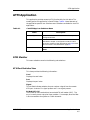
What Is in This Guide
The following outlines the organization of the Centillion 100 Management
Module Guide:
Chapter
Description
Chapter 1
Introduction
Describes the device, the management module
software, and model types. This chapter also
provides information on accessing device-specific
views.
Chapter 2
Device Views
Describes the Device views representing the
device.
Chapter 3
Configuration Views
Describes the Configuration views for the device
and the network management information
provided by the views.
Chapter 4
Application Views
Describes the Application views for the device and
application-specific information for this device.
This device does not contain an Events and Alarms chapter.
NOTE
9031561 E1
xi
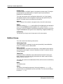
Conventions
Conventions
This guide uses the following conventions:
• Menu selections and buttons referenced in text appear in bold; for
example, Configuration or Detail.
• Button names appear in shadowed boxes when introducing paragraphs
describing their use; for example:
Help
• Menu navigation appears in order of selection; for example, Icon
Subviews -> Utilities -> Application.
• Referenced chapter titles and section headings appear in italics.
• Referenced documents appear in bold italics.
• References in blue are hypertext links for online documents.
Related SPECTRUM Documentation
When using this guide, you should have a clear understanding of SPECTRUM
functionality and navigation techniques as described in the Administration,
Operation, and following documentation:
Report Generator User’s Guide
Getting Started with SPECTRUM for Operators
Getting Started with SPECTRUM for Administrators
How to Manage Your Network with SPECTRUM
Preface
xii
Bay Networks Centillion 100
Management Module Guide
Other Related Documentation
Other Related Documentation
Refer to the following documentation for more information on managing TCP/
IP-based networks:
Martin, James, Kathleen Kavanagh Chapman, Joe Leben. Local Area
Networks: Architectures and Implementations, 2d ed. Englewood Cliffs,
NJ: Prentice Hall, 1994.
Rose, Marshall T. The Simple Book: An Introduction to Management of
TCP/IP-based Internets. Englewood Cliffs, NJ: Prentice Hall, 1991.
Stallings, William. Data and Computer Communications, 4th ed. New
York: Macmillan Publishing Company, 1994.
Tanenbaum, Andrew S. Computer Networks, 3d ed. Englewood Cliffs, NJ:
Prentice Hall, 1996.
9031561 E1
Preface
xiii
Other Related Documentation
Preface
xiv
Bay Networks Centillion 100
Management Module Guide
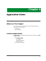
Chapter 1
Introduction
What Is in This Chapter
This chapter introduces the SPECTRUM management module for the Bay
Networks Centillion 100 Chassis. It describes the following:
• Bay Networks Centillion 100 Chassis
• SPECTRUM Support
- Accessing SPECTRUM Views
- Centillion 100 Roadmap
Bay Networks Centillion 100 Chassis
The Centillion 100 chassis is a switch that offers LAN-to-LAN, LAN-to-ATM,
and ATM-to-ATM switching within a medium to large enterprise network.
The Centillion chassis supports up to six switch modules; any combination of
TokenSpeed, ATMSpeed/155, and EtherSpeed modules. One module must
contain an integrated mcp (master control processor), which provides network
management functions. The Centillion 100 switch supports the
interconnection of up to 88 local LANs per switch (using five EtherSpeed
modules and one EtherSpeed/MCP module). Switch to switch communication
is provided with token ring, Ethernet, or ATM connectivity between Centillion
100 switches. In addition the Centillion 100 features:
• 3.2 GBs ATM backplane and 400 Mbs control bus
• Optional load sharing, redundant power supplies
• Hot swapable modules
• SNMP, BootP, and TFTP support
9031561 E1
1-1
SPECTRUM Device Management
SPECTRUM Device Management
SPECTRUM management modules are software packages that provide
templates for creating models of devices. These templates, called model types,
specify attributes that correspond to objects defined in the Management
Information Bases (MIBs) which govern the operation of the device or
application to be modeled.
SpectroGRAPH displays models as icons. These icons provide color-coded
status information and double-click access to other views that contain detailed
configuration and performance information. The models that are represented
by these icons reside in the SpectroSERVER database, where they are
continuously updated with new information retrieved during the polling cycle.
The model type name of the device for this management module is
HubBayCent100.
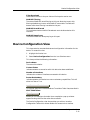
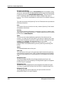
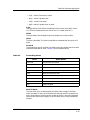
Accessing SPECTRUM Views
Icons and labels that display information within an icon provide access to
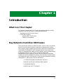
SPECTRUM views. This is done thorugh double-click zones (Figure 1-1) and
Icon Subviews menus (Figure 1-2).
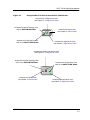
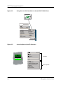
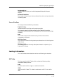
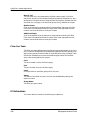
To access the Icon Subviews menu as shown in Figure 1-2 and Figure 1-3:
1. Highlight the icon or label.
2. From the View menu, select Icon Subviews or click the applicable mouse
button (middle or right). Refer to Getting Started with SPECTRUM for
Operators for information on configuring your mouse.
Introduction
1-2
Bay Networks Centillion 100
Management Module Guide
SPECTRUM Device Management
Accessing SPECTRUM Views
Figure 1-1.
Using Double-Click Zons to Access SPECTRUM Views
Accesses the Configuration view;
see Chapter 3, Configuration Views.
Accesses the Device Topology view;
refer to SPECTRUM Views.
Model Name
Accesses the Device view;
see Chapter 2, Device Views.
HubBayCent100
Accesses the Performance view;
refer to the SPECTRUM Views.
Accesses the Application view;
see Chapter 5, Application Views.
Accesses the Model Information view;
see Chapter 3, Configuration Views.
Accesses the Device Topology view;
refer to the SPECTRUM Views.
Accesses the Performance view;
refer to the SPECTRUM Views.
Model Name
HubBayCent100
Accesses the Device view;
see Chapter 2, Device Views.
9031561 E1
Accesses the Application view;
see Chapter 5, Application Views.
Introduction
1-3
SPECTRUM Device Management
Accessing SPECTRUM Views
Figure 1-2.
Using the Icon Subviews Menu to Access SPECTRUM Views
Model Name
HubBayCent100
View
Go Back
Ctrl+b
Go Up
Icon Subviews
View Path
New View
Bookmarks
View History
Current View Info...
Notes...
Jump by name...
Figure 1-3.
Accessing Device-Specific Subviews
13
ON
ETHERNET
0:01D:17:2F:CA
134.141.27.20
1
Introduction
1-4
Close
Ctrl+c
Navigate
Alarms
Performance
Notes...
Utilities
Zoom
Device
Close
Alt+F4
Navigate
Alarms
Performance
Notes...
Utilities
Zoom
Detail
IF Status
IF Configuration
IF Address Translation Table
Network Information Panel
Thresholds
IF Extensions
Model Information
Common
Device-Specific
Bay Networks Centillion 100
Management Module Guide
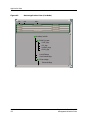
Spectrum Views Roadmap
Spectrum Views Roadmap
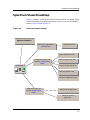
Figure 1-4 shows a “roadmap” of the SPECTRUM views for this device. These
views are accessible from double-click zones (Figure 1-1) and Icon Subviews
menus (Figure 1-2 and Figure 1-3).
Figure 1-4.
Spectrum Views Roadmap
Performance View; refer to the
Operator’s Reference.
Device Views; see Chapter 2,
Device Views.
Logical Device View
Agent Configuration View
Configuration Views; see
Chapter 3, Configuration
Device Configuration View
Views.
Chassis Configuration View
Model Name
HubBayCent100
ATM Configuration View
Interface Configuration View
Application Views; see
Chapter 4, Application
Views.
Centillion ATM application.
Centillion Common
application.
9031561 E1
Introduction
1-5
Spectrum Views Roadmap
Introduction
1-6
Bay Networks Centillion 100
Management Module Guide
Chapter 2
Device Views
What Is in This Chapter
This chapter provides a description of the Device views for the Bay Networks
Centillion 100 Chassis Management Module. The Device view allows you to
display a logical representation of the switch.
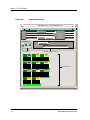
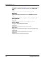
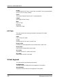
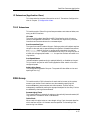
Logical Device View
The Logical Device view is a representation of the device configuration. If the
configuration of the device changes during the polling cycle, SPECTRUM
automatically updates the view. Figure 2-1 shows the Logical Device view.
9031561 E1
2-1
What Is in This Chapter
Logical Device View
Figure 2-1.
Logical Device View
DVBANNER View - of type HubBayCent100
* File
View
Help?
Model
Contact
Manufacturer
Description
Device Type
Location
Primary Application
Model Name
HubBayCent100
Filter
ON
1
0
Board
0
Port
iso88023
0:5:0:2C:5F:F8
0.0.0.0
Interface Options Panel
0
Board
0
Port
iso88025
0:5:0:2C:5F:F8
0.0.0.0
ON
3
1
16
other
0:5:0:2C:5F:F8
172.19.56.13
OFF
OFF
9
1
Board
6
Port
iso88023
0:A0:0:34:FA:1F
0.0.0.0
0
10 OFF
1
1
Board
3
Port
iso88023
0:A0:0:34:FA:1F
0.0.0.0
Board
7
Port
iso88023
0:A0:0:34:FA:1F
0.0.0.0
0
0
OFF
7
Interface Icons
ON
11
1
Board
4
Port
iso88023
0:A0:0:34:FA:1F
0.0.0.0
1
Board
8
Port
iso88023
0:A0:0:34:FA:1F
0.0.0.0
0
4
0
4
OFF
6
0
Board
Port
OFF
5
1
Board
2
Port
iso88023
0:A0:0:34:FA:1F
0.0.0.0
0
ON
Serial Number
Interface Description
0
2
Bridging
Phy Addr
Device Icon
Device Views
2-2
System Up Time
Network Address
OFF
8
1
Board
1
Port
iso88023
0:A0:0:34:FA:1F
0.0.0.0
1
Board
5
Port
iso88023
0:A0:0:34:FA:1F
0.0.0.0
0
0
Bay Networks Centillion 100
Management Module Guide
What Is in This Chapter
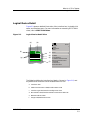
Logical Device Detail
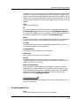
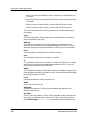
Logical Device Detail
Figure 2-2 shows a detailed illustration of the Interface icon, its double-click
zones, and Subviews menu. For more information on accessing SPECTRUM
views, refer to SPECTRUM Views.
Figure 2-2.
Logical Device Detail View
(a)
(h)
(b)
ON
1
0
Board
Port
iso88023
0:5:0:2C:5F:F8
(g)
(c)
0
0.0.0.0
(d)
(e)
0
(f)
Close
Alt+F4
Navigate
Alarms
Performance
Notes...
Utilities
Zoom
Detail
IF Status
IF Configuration
IF Address Translation Table
Network Information Panel
Thresholds
IF Extensions
Model Information
The following defines the interface icon labels a-f, shown in Figure 2-2, and
any double-click zones that can be accessed from this icon.
a. Interface Label
b. Administrative Status Label/Interface Status View
c. Interface Type Label/Interface Configuration View
d. Mac Address Label/Interface Address Translation Table View
e. Network Address Label
f.
9031561 E1
Gauge Label/Performance View
Device Views
2-3
What Is in This Chapter
Logical Device Detail
g. Port # Label
h. Board # Label
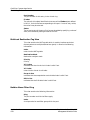
Interface Label
This label displays the interface number.
Administrative Status Label
This label displays the status of this interface. Double-click this label to open
the Interface Status View described on page 2-4. Table 2-1 lists the possible
status values.
Table 2-1.
Administrative Status Values
Color
Status
Description
Green
ON
Port is operational.
Blue
OFF
Port is off.
Red
TST
Port is in the test mode.
Interface Status View
The Interface Status View provides the following information for the selected
interface:
Operational Status
A read-only indicator displaying the current operational state of the interface.
The possible states are ON, OFF, Testing, and Default.
Administrative Status
A drop-down menu button that allows you to select the operational state of the
interface. The possible states are ON, OFF, Testing, and Default.
InterfaceType Label
This label displays the interface type. For a listing of all interface types refer
to SPECTRUM Views. Double-click this label to open the Interface
Configuration View, described in Chapter 3, Configuration Views.
Device Views
2-4
Bay Networks Centillion 100
Management Module Guide
What Is in This Chapter
Logical Device Detail
MAC Address Label
This label displays the MAC address of the device interface. Double-click this
label to open the Interface Address Translation Table View, described on page
2-5.
Interface Address Translation Table View
In addition to the following information, you can double-click any entry in the
table to access to the Interface Address Translation Information View, which
contains the same infomation as the table view with the exception that it
pertains only to the selected entry. For more information on table views, refer
to SPECTRUM Views.
Interface Index
The value identifying the port.
Physical Address
The physical (MAC) address of the port.
Network Address
The network (IP) address of the port.
Network Address Label
This label displays the current IP address of the interface.
Gauge Label
This label displays the performance statistic determined by the Gauge Control
Panel for this interface (refer to SPECTRUM Views for more information on
the Gauge Control Panel.) Double-click this label to open the Performance
view, described in SPECTRUM Views.
Port # Label
The port number to which this device is attached.
Board # Label
The board number which contains the port.
9031561 E1
Device Views
2-5
What Is in This Chapter
Interface Icon Subviews Menu Selections
Interface Icon Subviews Menu
Table 2-2 describes the Interface icon device-specific Subviews menu
selections. For information on accessing device-specific Subviews menus, refer
to SPECTRUM Views.
Table 2-2.
Interface Icon Subviews Menu
Menu Selection
Description
Detail
Opens the Interface Detail view, described in
SPECTRUM Views.
IF Status
Opens the Interface Status View, described on
page 2-4.
IF Configuration
Opens the Interface Configuration View,
described in Chapter 3, Configuration Views.
IF Address Translation Table
Opens the Interface Address Translation Table
View, described on page 2-5.
Network Information Panel
Opens the Network Information Panel View,
described on page 2-6.
Thresholds
Opens the Interface Thresholds View, described
on page 2-7.
IF Extensions
Opens the Interface Extensions Configuration
view, described in Chapter 3.
Model Information
Opens the Model Information View, described in
SPECTRUM Views.
Interface Icon Subviews Menu Selections
Network Information Panel View
The Network Information Panel View provides the follolwing information:
Name
The unique name assigned to the device.
Address
The IP address of the interface.
Mask
The mask address of the interface.
Device Views
2-6
Bay Networks Centillion 100
Management Module Guide
What Is in This Chapter
Interface Icon Subviews Menu Selections
Interface Threshold View
The Interface Threshold View provides the following information:
Load Threshold
The ON and OFF values are set to determine the point at which a load alarm
will be turned on or off.
Packet Rate Threshold
The ON and OFF values are set to determine the point at which a packet
transmission alarm will be turned on or off.
Error Rate Threshold
The ON and OFF values are set to determine the point at which an error
alarm will be turned on or off.
% Discarded Threshold
The ON and OFF values are set to determine the point at which a discarded
threshold alarm will be turned on or off.
Next Boot Net Mask
Displays the subnet mask for the interface that will be used for the next boot.
If no subnet mask is used, then the value is 0.0.0.0. The current subnet mask
for the interface is found in the IP Address Table.
Load Server Addr
Displays the IP address of the load server for the configuration file and/or the
image file. If the IP address is not used, then the value is 0.0.0.0.
Valid Flag
Indicates whether the configuration and image file(s) or either were
downloaded from this interface and whether the file names are unchanged.
Table 2-3 lists these values and their descriptions.
Table 2-3.
Valid Flag Status Values
Value
Description
valid
Configuration and/or image file(s) downloaded from this
interface are currently in use.
invalid
Configuration and/or image files downloaded from this
interface are not in use (this may also mean that there are
no files downloaded from this interface).
Config File Name
Displays the name of the configuration file currently associated with the
interface. When not used, the value is a zero length string.
Image File Name
Displays the name of the image file(s) currently associated with the interface.
Some agents in special situations may support a value which contains
multiple file names instead of a single file name. Multiple names are specified
9031561 E1
Device Views
2-7
What Is in This Chapter
Interface Icon Subviews Menu Selections
as a list of file names separated by semicolons (;). When this object is not used,
the value is a zero length string.
Write Configuration Settings to NVRAM
Provides a button that allows you to write the configuration settings to nonvolatile random access memory (NVRAM). This causes the current
configuration settings to be written to local non-volatile storage. These
settings are described in Table 2-4.
Table 2-4.
Write Configuration Settings to NVRAM Status Values
Value
Device Views
2-8
Description
valid
contents valid
write
write configuration settings to local storage (such as
NVRAM)
other
some unknown or other state
Bay Networks Centillion 100
Management Module Guide
Chapter 3
Configuration Views
What Is in This Chapter
This chapter describes the Configuration views available for the Bay
Networks Centillion 100 Chassis. These views display network configuration
and operating information for the device and its interfaces.
The following Configuration views are available for this device:
•
•
•
•
Interface Configuration
Chassis Configuration
Agent Configuration
ATM Configuration
- ATM ELAN
- ATM Packet Circuit
- ATM Cell Circuit
- ATM Port
• Interface Extensions Configuration
• Device Configuration
9031561 E1
3-1
Interface Configuration View
Interface Configuration View
This view contains more detailed network configuration information for the
device interface. To access this view:
1. Highlight the Device Icon within the Logical Device view.
2. Select IF Configuration from the Icon Subviews menu.
This view provides the following information:
Operation Status
The operational state of the interface, values are on or off
Admin Status
The administrative status of the interface, possible values are on, off, and
testing
Last Change
The last time, System Up Time, that a change was made to this interface
configuration.
IP Address/Network Mask
The IP Address and Network mask of the interface.
Physical Address
The physical (MAC) address of the interface.
Bandwidth
Displays the estimated bandwidth of the interface, measure in bits per second.
For interfaces that do not vary in bandwidth or for which no accurate estimate
can be made, a nominal bandwidth is displayed.
Packet Size
Displays the size of the packet on the interface.
Queue Length
Displays the number of packets in the queue.
Chassis Configuration View
This view contains more detailed network configuration information about the
device chassis. To access this view:
1. Highlight the Device Icon.
2. Select Chassis Configuration from the Icon Subviews menu.
This view provides the following information:
Chassis Type
The type of chassis.
Configuration Views
3-2
Bay Networks Centillion 100
Management Module Guide
Chassis Configuration View
Backplane Type
The type of chassis backplane.
Ps1 Fail Status
Power supply 1 failure indicator. A value of 0 indicates failure.
Ps2 Fail Status
Power supply 2 failure indicator. A value of 0 indicates failure.
Fan Fail Status
System chassis fan failure status. A value of 0 indicates failure on one or both
of the system fans.
Serial Number
The chassis serial number.
Part Number
The chassis part number.
Also, this view contains a slot configuration table which enables the user to
view infomation pertaining to all slots on the device. The table contains the
following information:
Board
The chassis slot number. Valid entries are system dependent, based on the
chassis type.
Module Type
The module type.
Hardware Version
The hardware version of the module.
Serial Number
The module serial number. The format is 3 BCD digits.
Software Version
The software version of the module.
Status
This indicates the operational status of the module. Possible values are ok and
fail.
Reset
This indicates the reset state of the module. Writing with the value reset (2)
will reset the module.
Config Delete
Setting this object causes the configuration of the module to be deleted. When
read this object has a value of false (2).
Config Media Type
The configured card media type. In the case of a card mismatch, the
configured media type and the card type will not match
9031561 E1
Configuration Views
3-3
Agent Configuration View
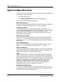
Agent Configuration View
This view contains more detailed network configuration information about the
device agent. To access this view:
1. Highlight the Device Icon.
2. Select Agent Configuration from the Icon Subviews menu.
This view provides the following information:
Max Packet Info Size
The system maximum packet information field size. Changing the maximum
information size does not take effect until the next system reset.
Configuration Mode
This variable describes the current mode of bridging configuration in the
switch. The bridging mode applies to all ports. The value other(1) is a readonly indication that the system is in a user customized the system
configuration. Setting this object will save the configuration into flash and
issue a system reset command.
Max Performance Mode
The current value of the system maximum performance mode. Setting this
value to enabled causes the system to perform in maximum performance
mode. Default is disabled. This variable does not take effect until the next
system reset.
Save Config to Memory
Save the current configuration into flash memory. When read, this value is
always clear (1). The value may only be set to the set (2) state.
Admin Mac Address
The system's locally administered MAC address. The current operation MAC
address may be obtained by the ifPhysAddress entry in the ifTable. This
parameter will take effect only after a reset is issued.
Login
The system login object. This object is used to login a network management
station to the system for configuration. The format of the login request follows:
login indicator.login password, where the login indicator is a single byte of the
value 1 = logoff, 2 = login, or 3 = set password and the password is the system
password. The password must be supplied for login or for altering the
password. A manager must first login to the system before altering the
password. When read, the first octet is returned, indicating whether a
managment station is currently logged in to the system.
Management TRing Number
A unique ring number assigned to the system's managment entity. This ring
will not appear as a source-route hop as it is seen only in frames destined to or
sourced from the system management entity.
Configuration Views
3-4
Bay Networks Centillion 100
Management Module Guide
Agent Configuration View
Configuration Protocol
The protocol used to retrieve system configuration. Flash indicates that the
configuration is read from the flash. tftpNoSave indicates that the TFTP
protocol should be used to retrieve the current configuration. The new
configuration is not saved into flash, it is up to the user to save the
configuration if desired. The new configuration will not take effect until the
next system reset. tftpSave indicates that the newly uploaded configuration
will be saved into flash, thus it may be use to permanently update a
configuration. The system is automatically reset.
Configuration Filename
The name of the configuration file that is sent to the server. The actual boot
protocol used to retrieve the file is determined by Configuration
Protocol. This parameter may be configured via the network boot protocol.
Configuration Source
An indication of how the system was actually configured. flashConfig
indicates that the current configuration was obtained via flash.
remoteConfig indicates that the configuration was obtained via the protocol
determined by configProtocol.
IP Address
The system's IP address. The current operational IP address may be obtained
by the ipAdEntAddr entry in the ipAddrTable. This parameter will take
effect only after a reset is issued.
Subnet Mask
The system's IP subnet mask. The current operational IP subnet mask may be
obtained by the ipAdEntNetMask entry in the ipAddrTable. This
parameter will take effect only after a reset is issued. The parameter is not
saved unless written to flash.
Bcast Address
The system's IP broadcast address. The current operational IP broadcast
address may be obtained by the ipAdEntBcastAddr in the ipAddrTable.
This parameter will take effect only after a reset is issued. This parameter is
not saved unless written to flash.
Default Gateway
The system's default getway IP address. the current operational default
gateway's IP address can be obtained from the ipRoutingTable. This
parameter will take effect only after a reset is issued. This parameter is not
saved unless written to flash.
Configuration Server
The IP address to which the requests for configuration files are sent. The
protocol used to retrieve the configuration is determined by the
Configuration Protocol object. This parameter may be set dynamically
as established by the ipConfigProtocol object.
IF Configuration Protocol
The protocol used to configure IP addressing information. Possible values are
flash and bootp.
9031561 E1
Configuration Views
3-5
Agent Configuration View
TFTP Start
Setting sysTFTPStart to tftpGet initiates a file transfer to the agent
(download); tftpPut initiates a file transfer to the server (upload).
TFTP IP Address
The IP Address of the TFTP server.
TFTP File Name
The file name of the file to retrieve (tftpGet), or the name of the file to create
(tftpPut).
TFTP File Type
The type of file image to upload/download. The file type indicates to the agent
what kind of file it is receiving. configuration indicates an update of the
system configuration. imageCode indicates a code upgrade of the operational
proms. bootCode indicates a code upgrade of the boot proms.
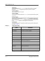
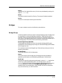
TFTP Result
The result of the last TFTP operation. Possible results and their descriptions
are listed in Table 3-1.
Table 3-1.
TFTP Results Table
Result
Description
not initialized
xferInProgress
a transfer is currently in progress
okay
okay
otherTFTPError
other type of TFTP error
fileNotFound
check for valid file name
accessError
access error
diskFull
server disk is full
illegalTFTPOperation
illegal TFTP operation
invalidTFTPTransactionID
invalid TFTP transaction ID
fileExists
file already exists
noSuchUser
invalid user
noResources
no resources to start
noResponse
check for valid server IP
flashError
flash programming error
configMismatch
configuration mismatch
configChecksumError
configuration checksum error
Configuration Views
3-6
clear
Bay Networks Centillion 100
Management Module Guide
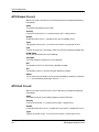
ATM Configuration
This selection provides the following views:
ATM Configuration
This menu selection contains four subviews which provide detailed ATM
network configuration information To access these views:
1. Highlight the CentATMApp within the Application view.
2. Select ATM Configuration from the Icon Subviews menu.
3. Select the subview you wish to view.
This selection provides the following views:
ATM ELAN View
Within this view is the ATM ELAN Table view which provides the following
information:
Index
The index to the ATM ELAN Table.
ELAN Type
The ELAN type. Possible values are ATMELANXob and ATMELANBe.
Enable
Enable bit of the ELAN; 1 = enable ELAN, 2 = disable ELAN.
All PVC Circuits
Return all PVCs (Permanent Virtual Circuits) that belong to this ELAN. Each
circuit id is a 32 bit field.
Card
Virtual card number. Currently only 13 is accepted.
Port
Virtual port number. Currently this number is the ELAN id.
Segment ID
Virtual port number. Currently this number is the ELAN id.
Status
The current status of the entry. Entries may be added by specifying a value of
valid, and removed by entering invalid.
Segment Type
The virtual segment type.
9031561 E1
Configuration Views
3-7
ATM Configuration
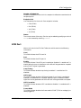
ATM Packet Circuit
ATM Packet Circuit
Within this view is the ATM Circuit Table view which provides the following
information:
Index
The index to the packet circuit table.
Priority
Priority bit of the circuit. 1 = normal priority and 2 = high priority.
Enable
Enable bit of the circuit. 1 = enable circuit and 2 = disable circuit.
Type
The type bit of the circuit. 1 = virtual circuit and 2 = virtual path circuit.
Cost
The cost of the circuit. The range is from 0 to 255 with 0 being the lowest cost.
ELAN Index
The ELAN id to which this circuit belongs.
Card Port
The ATM card/port to which this circuit belongs.
VPI
The packet circuit VPI (Virtual Path Identifier) number.
VCI
The packet circuit VCI (Virtual Channel Identifier) number.
Status
The current status of the entry. Entries may be added by specifying a value of
valid, and removed by entering a value of invalid.
ATM Cell Circuit
Within this view is the ATM Cell Circuit Table which provides the following
information:
Index
The index to the cell circuit table. Supports a total of 256 cells.
Priority
Priority bit of the cell. 1 = normal priority and 2 = high priority.
Enable
Enable bit of the cell circuit. 1 = enable cell circuit and 2 = disable cell circuit.
Type
Type bit of the cell circuit. 1 = virtual circuit and 2 = virtual path circuit.
Configuration Views
3-8
Bay Networks Centillion 100
Management Module Guide
ATM Configuration
ATM Port
Number of Endpoints
Number of endpoints in the circuit. An endpoint is defined as a combination of
card/port/vpi/vci.
Endpoint List
List of endpoints for the circuit. Each endpoint includes:
• Card (32 bit)
• Port (32 bit)
• Vpi (32 bit)
• Vci (32 bit)
Status
The current status of the entry. Entries may be added by specifying a value of
valid, and removed by entering invalid.
ATM Port
Within this view is the ATM Port Table view which contains the following
information:
Card
This field indicates the ATM card id.
Port
This field indicates the ATM port id.
Enable
This field indicates if the ATM port is enabled or disabled. 1 = enable and 2 =
disable. When the port is disabled no cell traffic will be generated or accepted
and no SONET signal is generated.
Loop Timing
This field indicates whether loop timing is enabled. 1 = enabled and 2 =
disabled.
HEC Coset
This field indicates whether HECCoset (Header Error Check) is enabled or
disabled. 1 = enabled and 2 = disabled. When the port is disabled a SONET
signal will not be generated and cell traffic will not be generated or accepted.
HEC Correction
This field indicates whether HEC is enabled or disabled. 1 = enabled and 2 =
disabled.
Frame Mode
This field indicates whether the frame mode is SONET, SDH or notApply (no
cable plugged in).
9031561 E1
Configuration Views
3-9
Interface Extensions Configuration
This view provides the following information:
Local Loop
This field indicates whether local loop is enabled or disabled. 1 = enabled and
2 = disabled.
Remote Loop
This field indicates the status of loop timing. 1 = enabled and 2 = disabled.
When the port is disabled no SONET signal is generated and no cell traffic is
generated or accepted.
Force HEC Error
This field indicates the status of forcing cell header checksum error. 1 =
enabled and 2 = disabled.
Scrambling
This value indicates the status of scrambling. 1 = enabled and 2 = disabled.
Interface Extensions Configuration
This view contains more detailed network configuration information for the
Interface Extensions. To access this view:
1. Highlight the Device Icon within the device view.
2. Select IF Extensions from the Icon Subviews menu.
This view provides the following information:
Index
A unique value representing each interface.
Card
The card number associated with this interface.
Port
The port number associated with this interface.
Filter Enable
The state of filtering on this port. If TRUE, then filters are enabled. The filter
port table will become valid when filters are downloaded to the port via setting
the cnIfFilterDownload object. In the high-perfomrance mode, filters will
be disabled on all ports execpt the management port
Forwarding Identifier
This object references the correspsonding instance in the MIB object which
describes the ports forwarding function. For example, if the port is
participating in bridging, then this object contains the OID of the
bridgeGroupPortTable. If this information is not present, its value is set to
the OBJECT IDENTIFIER { 0 0 }.
Configuration Views
3-10
Bay Networks Centillion 100
Management Module Guide
Device Configuration View
Filter Download
Downloads the filters to the port. Value will always be read as zero.
NetBIOS Filtering
The state of NetBIOS name filtering on this port. Note that a port with
filtering disabled may have a valid NetBIOS name table. The table will
become valid when filtering is enabled on the port.
NetBIOS Bcast Discard
This indicates whether NetBIOS broadcasts are to be discarded on this
interface.
NetBIOS Name Proxy
The state of NetBIOS name proxying on this port.
Device Configuration View
This view contains more detailed network configuration information for the
device. To access this view:
1. Highlight the Device Icon.
2. Select Device Configuration from the Icon Subviews menu.
This view provides the following information:
Device Name
The name of the device.
Contact Status
Indicates whether a connection with this device has been established.
Number of Interfaces
Indicates the number of interfaces connected to this device.
Router Redundancy
Indicates whether this device has router redundancy capabilities. This will
either be False or True.
IF Address Translation
This button opens the Interface Address Translation Table View, described in
SPECTRUM Views.
Reconfigure
Allows you to reconfigure the table. Upon completion a pop-up window
appears stating that that the action was successful.
The Device Configuration view also provides you with an Interface
Configuration Table which allows double-click access to the Interface
9031561 E1
Configuration Views
3-11
Device Configuration View
Configuration view (described on Page 3-2), as well as provides the following
information. For additional information on tables, refer to SPECTRUM
Views.
Index
Indicates the index number to which the interface is attached.
Description
Displays a description of the interface and its location within the switch.
Type
Indicates the type of interface attached to the device. Some possible types are
ATM, FDDI, iso88023, etc. For a complete list of interface types refer to
SPECTRUM Views.
Bandwidth
Displays the current bandwidth value being used by the interface.
Physical Address
The physical ( MAC) address of the interface.
Oper Status
Displays the current operational status of the interface.
Admin Status
Displays the current Administrative status of the interface, either on or off.
Last Change
Displays when the last change was made to the interface.
Packet Size
Displays the size of the packet on the interface.
Configuration Views
3-12
Bay Networks Centillion 100
Management Module Guide
Chapter 4
Application Views
What Is in This Chapter
This chapter describes the Bay Networks Centillion 100 Chassis devicespecific applications listed below.
• CentATMApp
• CentCommonApp
Common Applications
This device supports the following common applications described in the MIB
II Applications:
• MIB-II (SNMP2_Agent)
- ICMP (ICMP_App)
- IP (IP2_App)
- System (System2_App)
- UDP (UDP2_App)
• RS-232 App (RFC1317App)
9031561 E1
4-1
Application View
Device Application View
Application View
The Application view displays information on any application supported by
the device. Each application appears as an icon in the Application view. Access
application-specific Model Information Views, Performance Views, and Detail
Views from these icons. Depending on the specific application, various
additional views are also available and discussed in this section.
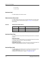
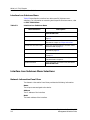
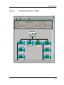
Device Application View
This view shows the common and device-specific applications supported by
this device and provides access to application-specific information.
Figure 4-1 shows an example of an Application view in the Icon mode.
Figure 4-2 shows an example of an Application view in the List mode.
To change the display mode, select View -> Mode -> List or Icon.
Application Views
4-2
Bay Networks Centillion 100
Management Module Guide
Application View
Device Application View
Figure 4-1.
Device Application View (Icon Mode)
BANNERView of type HubBayCent100
*
File
View
Model Name
Help?
Network Address
Sys Up Time
Contact
Manufacturer
Description
Device Type
Location
Serial Number
Primary Application
Model Name
HubBayCent100
.39_MIB-II
Cent ATM Ap
Common Ap
SNMP2_Agent
CentATMApp
CentCommon
SNMP2_Agent
27.39_ICMP
ICMP_App
ICMP_App
9031561 E1
CentATMApp
CentCommon
Ethernet AppI
EthernetAppli
Ethernet Appli
App_004
4
App_004
.27.39.IP2
App_006
IP2_App
6
IP2_App
App_006
Application Views
4-3
Application View
Figure 4-2.
Device Application View (List Mode)
BannerView of type HubBayCent100
*
File
Model Name
View
Help?
Network Address
Sys Up Time
Contact
Manufacturer
Description
Location
Device Type
Primary Application
Serial Number
HubBayCent100
SNMP2_Agent
ICMP_App
IP2_App
System2_App
UDP2_App
CentATMApp
CentCommonApp
EthernetApp
EthernetIfApp
Application Views
4-4
Bay Networks Centillion 100
Management Module Guide
ATM Application
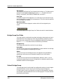
ATM Application
This application provides access to ATM functionality for this device. The
model type for this application is CentATMApp. Table 4-1 describes each of
the application-specific Icon Subviews menu selections available for the ATM
application.
Table 4-1.
CentATMApp Icon Subviews Menu
Menu
Description
ATM Configuration
Opens four sub menu selections described in Chapter 3,
ConfigurationViews.
ATM Monitor
Contains three sub selections: the ATM Port Statistics view,
described in Chapter 3, Configuration Views, the ATM
ELAN PVC Statistics view, described on page 4-6, and the
ATM PVC Status view, described on page 4-6.
Model Information
Opens the Model Information View, refer to SPECTRUM
Views.
ATM Monitor
This menu selection contains the following sub selections:
ATM Port Statistics View
This view provides the following information:
Card
Displays the card index.
Port
Displays the port index.
Signal
This bit field indicates whether the port receives a signal from the remote
ATM port. A value of 1 = signal present and 2 = no signal present.
RX Bad HEC Cell
The number of cells received that have a bad ATM cell header (HEC). The
error is usually due to a physical layer problem. For example, when the fiber
is first connected to the system or a clock mismatch.
9031561 E1
Application Views
4-5
ATM Application
ATM Monitor
Rx Dma Drop Cell
The number of cells received but discarded by the ATM header validation
checking. The error is usually due to an incorrectly configured VPI/VCI, or
other configuration error.
Rx Good Cell
The number of cells received that are valid.
Tx Dma Drop Cell
The number of outgoing cells dropped due to congestion.
Tx Good Cell
The number of cells transmitted.
ATM ELAN PVC Statistics View
This view provides the following information:
ELAN Index
The ELAN index
PVC In Ucast Pkt
The number of unicast packets that is received from this ELAN PVC.
PVC In Mcast Pkt
The number of multicast packets that is received from this ELAN PVC
PVC Out Ucast Pk
The number of unicast packets that is transmitted from this ELAN PVC.
PVC Out Mcast Pk
The number of multicast packets that is transmitted from this ELAN PVC.
ATM PVC Status
This view provides the following information:
Index
This field is the index of the circuit.
ELAN ID
This field is the index of the ELAN this circuit belongs to.
RS Info
This field is based on the aging timer of a remote switch. If the local switch
has not received any packets from the remote switch for a period of time, then
it is declared as non-valid.
Application Views
4-6
Bay Networks Centillion 100
Management Module Guide
Centillion Common Application
ATM Monitor
RS Mac Address
This field lists the remote switch's MAC address. If the
ATMInterSwitchPvcRemoteSwitchInfoValid object is 1, then this field
contains valid info. Otherwise, this field contains the last learned info.
RS PVC Status
This field is set if the remote switch receives packets from this switch. If
ATMInterSwitchPvcRemoteSwitchInfoValid object is 1, then this field
contains valid info. Otherwise, this field contains the last learned info.
STP State
This field indicates the STP port state of the circuit.
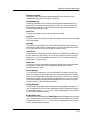
Centillion Common Application
This application provides access to common functionality for this device. The
model type for this application is CentCommonApp. Table 4-2 describes each
of the application-specific Icon Subviews menu selections available for the
Common application.
Table 4-2.
CentCommonApp Icon Subviews Menu Selections
Menu Selection
9031561 E1
Desription
Chassis Configuration
Opens the Chassis Configuration view, described in
Chapter 3, Configuration Views.
Agent Configuration
Opens the Agent Configuration view described in Chapter
3,Configuration Views.
Lan Port Table
Opens the Lan port Table view described on Page 4-8.
Station Group
Opens the Station Group view described on Page 4-8.
Trap Receiver
Opens the Trap Receiver view described on Page 4-9.
Netbios Group
Opens the Netbios Group view described on Page 4-10.
Card Monitor Table
Opens the Card Monitor Table view described on Page 4-11.
Global Ring Table
Opens the Global Ring Table view described on Page 4-12.
Bridges
This menu selection contains five sub-selections: The
Bridge Group view described on Page 4-15, the Virtual
Bridge Group view described on Page 4-16, the Bridge Base
view described on Page 4-17, the Spanning Tree view
described on Page 4-18, and the Source Routing view
described on Page 4-21.
Routing Information
This menu selection contains two sub-selections: the RIF
Table view described on Page 4-21, and the RID Table view
described on Page 4-22.
Application Views
4-7
Centillion Common Application
Lan Port Table
Table 4-2.
CentCommonApp Icon Subviews Menu Selections (Continued)
Menu Selection
Desription
Virtual Segment
Opens the Virtual Segment view described on Page 4-22.
Filters
This menu selection contains two sub-selections: the Filter
Group Table view described on Page 4-24, and the Filter
Port Table view described on Page 4-26..
IF Extensions
This menu selection contains two sub-selections: the IF
Extensions view described on Page 4-27, and the TR IF
Extension view described on Page 4-27.
Fdb Group
Opens the Fdb Group view described on Page 4-27.
Model Information
Opens the Model Information view described in
SPECTRUM Views.
Lan Port Table
This table provides the following information:
Index
Index into the LAN Port Table.
State
Current state if the port is enabled.
In Use
Current state if the port is enabled.
Body Type
Port body type.
Daughter1 Type
Daughter card 1 interface.
Daughter2 Type
Daughter card 2 interface.
Daughter3 Type
Daughter card 3 interface.
Local Ring Index
Index into the local ring table.
Station Group
This table provides station information known in the system:
Application Views
4-8
Bay Networks Centillion 100
Management Module Guide
Centillion Common Application
Trap Receiver
MAC Address
The stations MAC (physical) address. The station table is indexed by the low
13 bits of this address.
Card
Card number attached to this station.
Port
Port number attached to this station.
In Use
This bit indicates whether the entry is valid.
Local
Indicates whether the station is locally attached.
Static
Indicates whether the station is static.
DTAG Type
Indicate DTAG type. Clear (0) indicates the DTAG specifies a card and port
combination.
Duplicate
Indicates next station is a duplicate MAC address.
Next Index
Index into the station collision table.
RIF In Use
Indicates whether the RIF (Routing Information Field) is set.
RIF Index
Index into the RIF table. Static RIFs may be configured by first adding or
retrieving the appropriate RIF index object in the RIF table.
VCI State
Type of VCI connection.
VCI Index
Index into the VCI table.
Trap Receiver
This view provides the following information:
Get Community
The system get community string.
Set Community
The system set community string.
9031561 E1
Application Views
4-9
Centillion Common Application
Netbios Group
Enable Traps
Indicates whether the SNMP agent is permitted to process traps. This object
provides global trap enable status, as specific traps may be enabled or
disabled on an individual basis.
This view also contains the Trap Receiver table which is a list of network
management stations that are capable of receiving traps generated by the
system. This table contains the following information:
Address
The IP address of the network managment entity that will receive traps.
Status
Setting this object to invalid has the effect of invalidating the corresponding
entry in the sysSNMPReceiverTrapTable. On a read, the value valid is
returned. Entries are added into the table by specifying a previously unknown
trapRcvrNetAddress along with the corresponding trapRcvrCommunity.
Community
The community string to use for traps sent to this trap receiver.
Netbios Group
This view contains the following information:
Table Aging Timer
The timeout period, in seconds, for aging out dynamicallly learned Netbios
names. The default value is 300 seconds.
Query Interval
The time period, in hundreds of milliseconds, in which Netbios name queries
are allowed to be bridged. A value of 0 disables this field. The default value is
5 (a half second).
Table Flush
Indicates whether the Netbios name table should be flushed. Flushing the
table removes all of the dynamically learned entries. When read this object
always returns a value of clear.
This view also contains the Netbios Name Table, which contains the following
information:
Name
The Netbios name.
Status
The status of the Netbios name entry. Setting this object to invalid (2)
causes the entry to be deleted from the name table. The value should always
be read as valid(1).
Application Views
4-10
Bay Networks Centillion 100
Management Module Guide
Centillion Common Application
Card Monitor Table
Station Address
The address of the station from which this name was learned or configured.
This object must be specified when adding an entry into the table.
VRing
The virtual ring number from which the entry was learned or configured. If
the switch is operating in a mode where virtual rings are invalid, then this
number will be 0. This object must be specified when adding an entry in the
table if appropriate.
Card
The card number from which the entry was learned or configured. If the
switch is operating in a mode where virtual rings are valid, then this number
will be 0. This object must be specified when adding an entry in the table if
appropriate.
Port
The port number from which the entry was learned or configured. If the
switch is operating in a mode where virtual rings are valid, then this number
will be 0. This object must be specified when adding an entry in the table if
appropriate.
Port Type
The type of port from which the entry was learned or configured.
Age
The amount of time (in hundredths of a second) before this entry is aged, or
the elapsed time since the entry was learned or configured.
Proxies
The number of times that the switch has proxied for this station.
Suppressed Queries
The number of Netbios name queries from this station which were suppressed
by the switch due to the configured name query interval.
Card Monitor Table
This view contains the following information:
Board
The card number index. Valid entries are system dependent based on the
chassis type.
Cells Received
The number of cells revceived by the card. This statistic is not maintained in
high-performance mode.
Cells Transmitted
The number of cells transmitted by the card. This statistic is not maintained
in high-performance mode.
9031561 E1
Application Views
4-11
Centillion Common Application
Global Ring Table
Cells Dropped
The number of cells dropped by the card.
SARReceived
The number of Segmentation And Reassembly (SAR) packets revceived by the
card. This statistic is not maintained in high-performance mode.
SARTransmitted
The number of SAR packets transmitted by the card. This statistic is not
maintained in high-performance mode.
SARDropped
The number of SAR packets dropped by the card.
MSIMsgs
The total number of MSI messages to and from the card. This statistic is not
maintained in high-performance mode.
Global Ring Table
This view contains the following information:
Global Ring
Index into the global ring table.
In Use
Indicates a valid entry if set.
Virtual Ring
Index into the virtual ring table.
VCI State
Virtual Circuit Index (VCI) state.
VCI Index
Index into the virtual circuit table.
Virtual Ring Table
This button opens the Virtual Ring Table view described below.
Virtual Ring Table
VRing
Virtual ring number.
In Use
Indicates a valid entry if set.
Application Views
4-12
Bay Networks Centillion 100
Management Module Guide
Centillion Common Application
Global Ring Table
MDTag
Forwarding Multicast Destination Tag (MDTag) to all ports on the ring.
Ports
The number of ports contained in the vitrual ring.
NB Filtering
The current state of NetBios Name Filtering on the virtual ring. Default is
disabled, i.e. no name filtering.
NB Bcast Discard
This indicates whether NetBIOS broadcast datagrams discard should be
discarded on this virtual ring.
NB Proxy
The current state of NetBios Name Proxying on the virtual ring. Default is
disabled, i.e. no name proxying.
ARE Hop Counts
All Routes Explorer (ARE) Hop Count in bytes.
STE Hop Count
Spanning Tree Explorer (STE) Hop Count in bytes.
Bridge Port Next
The corresponding bridge port number. If no bridge port is associated with
this ring, then zero is returned.
Virtual Ring Port
This button opens the Virtual Ring Port Table view described below.
MDTag
This button opens the Multicast Destination Tag View, described below.
Netbios Name Filter
This button opens the Netbios Name Filter Ring Table view described below.
Virtual Ring Port Table
This view contains the following information:
Virtual Ring
The virtual ring number.
Card Number
The card number for this entry in the virtual ring.
9031561 E1
Application Views
4-13
Centillion Common Application
Global Ring Table
Port Number
The port number for this entry in the virtual ring.
If Index
The value for this object identifies the instance of the ifIndex object defined
in MIB-II, for the interface corresponding to this port. If no such entry exists,
the value 0 may be returned.
Status
The current status of the entry. Entries may be added by specifying a value of
valid, and removed by setting the status to invlid.
Multicast Destination Tag View
This view contains the MDTag table which is used by interface cards that
forward packets to multiple destinations (ports). It contains the following
information:
Index
Index into the MDTag table.
Destination Mask
Destination card/port mask.
Priority
Priority.
VCI In Use
Indicates that the virtual circuit index is valid if set.
VCI Index
Index into the virtual circuit table.
Encap In Use
Indicates that the encapsulation control table index is valid if set.
RID In Use
Indicates that the RID table index is valid if set.
Netbios Name Filter Ring
This view contains the following information:
Ring
The port number to which the filters apply.
Index
A unique value for each filter group within the port.
Application Views
4-14
Bay Networks Centillion 100
Management Module Guide
Centillion Common Application
Bridges
Status
The status of this Netbios filter entry. Entries may be deleted by setting this
object to invalid(2).
Name
The Netbios name to match for filtering. The name will be blank padded.
Action
The action to take upon matching the name filter.
Bridges
This menu selection contains the following sub-selections:
Bridge Group
Centillion Networks switches support multiple bridging groups. Bridge groups
are identified by a unique bridge group identifier. These switches allow a
multiple number of bridge groups to be configured. The bridge configuration
MIB allows a management application to perform configuration across any of
the bridge groups.This view contains the following information:
Base Bridge Group Identifier
The bridge group identifier for which the standard bridging MIBS apply.
Modifications of the bridge group through the standard bridging MIBs effects
this bridge group only.
This view also contains the Bridge Group Table which provides you with the
following information:
Bridge Group
The unique identifier of this bridge group.
Status
The current status of the bridge group. Bridge groups may be added by
specifiying a valid status, and removed by specifying an invalid status.
Base Type
Indicates the type of bridging being performed. A value of none implies that
switching is performed between ports in this bridge group. A value of
unknown implies that some unknown bridging rules are applied on the ports
in this bridge group. Modifying the bridgeGroupBaseType requires a
complete reset of the bridge group. Other possible values are: transparentonly, sourceroute-only, srt, and translation.
9031561 E1
Application Views
4-15
Centillion Common Application
Bridges
Stp Protocol
The version of the Spanning Tree Protocol that is being run. This field may be
ignored if the bridgeGroupBaseType value is none. Possible values are:
none(1), unknown(2), decLb100(3), ieee8021d(4), and ibm(5).
Port Type
Indicates the type of the bridge ports. This value may only be altered if there
are no bridge ports currently in the bridge group. This value must be specified
during bridge group creation.
Next Port Index
The value of the next bridge port number which will be assigned by the
switch.
Bridge Group Port
This Button opens the Bridge Group Port Table view which is detailed below.
Bridge Group Port Table
This view contains a table which provides information about each port that is
associated with this bridge group. Ports may be added by specifying a valid
port index, and a valid status. Entries are deleted by setting the corresponsing
object to invalid. This table contains the following information:
Bridge Group
The bridge group identifier to which this port belongs.
Port Index
The value of the instance of the dot1dBasePort object, defined in the Bridge
MIB, for the bridge port corresponding to this port.
Status
The current status of the bridge port entry. Bridge ports may be added by
specifiying a valid status, and removed by specifying an invalid status.
IF Index
The value of the instance of the ifIndex object, defined in MIB-II, for the
interface corresponding to this port. Bridge ports are added by specifying the
ifIndex instance for the bridge port.
Virtual Bridge Group
This view opens the Virtual Bridge Port configuration table. A virtual bridge is
composed of either virtual rings or ports forming a logical bridge port.
Currently, each virtual ring comprises a unique virtual bridge port. Multiple
card and ports may be combined into a virtual bridge port. This view contains
the following information:
Application Views
4-16
Bay Networks Centillion 100
Management Module Guide
Centillion Common Application
Bridges
Virtual Bridge Next Port Number
The value of the next bridge port number which will be assigned by the
switch. When adding ports in transparent briding mode, the specified
virtualBridgePortConfigNumber must match this value.
This view also contains the Virtual Bridge Port Configuration table, which
provides the following information:
Virtual Bridge
The virtual bridge port number.
Card
The card number for this entry in the virtual bridge port.
Port
The port number for this entry in the virtual bridge port.
If Index
The value for this object identifies the instance of the ifIndex object defined
in MIB-II, for the interface corresponding to this port. If no such entry exists,
the value 0 may be returned.
Circuit
For a port which (potentially) has the same value of
virtualBridgeConfigIfIndex as another port, this object contains the
name of an object instance unique to this port. For example, in the case where
multiple ports correspond one-to-one with multiple ATM VCs, this value
identifies the ATM VC associated with this port.
Status
The current status of the entry. Entries may be added by specifying a value of
valid, and removed by setting the status to invalid.
Bridge Base
This view contains the following information:
Bridge Address
The MAC address used by this bridge when it must be referred to in a unique
fashion. It is recommended that this be the numerically smallest MAC
address of all ports that belong to this bridge. However, it is only required to
be unique. When concatenated with cndot1dStpPriority a unique
BridgeIdentifier is formed which is used in the Spanning Tree Protocol.
Number of Ports
The number of ports controlled by this bridging entity
Type
Indicates what type of bridging is being performed if a bridge is actually
performing a certain type of bridging this will be indicated by entries in the
9031561 E1
Application Views
4-17
Centillion Common Application
Bridges
port table for the given type. Possible types are: unknown, transparent-only,
source-route only, and srt.
Source Routed Frames Forward
Indicates whether the system will forward source routed frames if running in
transparent bridging mode. If this value is disabled(1), the system will drop
all source-routed frames. The default value is disabled(1).
This view also contains the Bridge port Table. Which is a table that contains
generic information about every port that is associated with this bridge.
Transparent, source-route, and srt ports are included. This table provides the
following information.
Port Number
The number of the port for which this entry contains bridge management
information.
If Index
The value of the instance of the ifIndex object, defined in MIB-II, for the
interface corresponding to this port.
Circuit
For a port which (potentially) has the same value of
cndot1dBasePortVirtualRing as another port on the same bridge, this
object contains the name of an object instance unique to this port. For
example, in the case where multiple ports correspond one-to-one with multiple
X.25 virtual circuits, this value might identify an (e.g., the first) object
instance associated with the X.25 virtual circuit corresponding to this port.
For a port which has a unique value of dot1dBasePortIfIndex, this object
can have the value { 0 0 }.
Spanning Tree
This view contains the following information:
Protocol Specification
An indication of what version of the Spanning Tree Protocol is being run. The
value decLb100(2) indicates the DEC LANbridge 100 Spanning Tree protocol.
IEEE 802.1d implementations will return 'ieee8021d(3)'. If future versions
of the IEEE Spanning Tree Protocol are released that are incompatible with
the current version a new value will be defined.
Priority
The value of the writeable portion of the Bridge ID, i.e., the first two octets of
the (8 octet long) Bridge ID. The other (last) 6 octets of the Bridge ID are
given by the value of cndot1dBaseBridgeAddress.
Time Since Topology Change
The time (in hundredths of a second) since the last time a topology change was
detected by the bridge entity.
Application Views
4-18
Bay Networks Centillion 100
Management Module Guide
Centillion Common Application
Bridges
Topology Changes
The total number of topology changes detected by this bridge since the
management entity was last reset or initialized.
Designated Root
The bridge identifier of the root of the spanning tree as determined by the
Spanning Tree Protocol as executed by this node. This value is used as the
Root Identifier parameter in all Configuration Bridge Protocol Data Units
(PDUs) originated by this node.
Root Cost
The cost of the path to the root as seen from this bridge.
Root Port
The port number of the port which offers the lowest cost path from this bridge
to the root bridge.
Max Age
The maximum age of Spanning Tree Protocol information learned from the
network on any port before it is discarded, in units of hundredths of a second.
This is the actual value that this bridge is currently using.
Hello Time
The amount of time between the transmission of Configuration bridge PDUs
by this node on any port when it is the root of the spanning tree or trying to
become so, in units of hundredths of a second. This is the actual value that
this bridge is currently using.
Hold Time
This time, in units of hundredths of a second, determines the interval length
during which no more than two Configuration bridge PDUs shall be
transmitted by this node.
Forward Delay
This time value, measured in units of hundredths of a second, controls how
fast a port changes its spanning state when moving towards the Forwarding
state. The value determines how long the port stays in each of the Listening
and Learning states, which precede the Forwarding state. This value is also
used, when a topology change has been detected and is underway, to age all
dynamic entries in the Forwarding Database.
Bridge Max Age
The value that all bridges use for MaxAge when this bridge is acting as the
root. The granularity of this timer is specified by 802.1D-1990 to be 1 second.
An agent may return a badValue error if a set is attempted to a value which
is not a whole number of seconds.
Bridge Hello Time
The value that all bridges use for HelloTime when this bridge is acting as the
root. The granularity of this timer is specified by 802.1D-1990 to be 1 second.
An agent may return a badValue error if a set is attempted to a value which
is not a whole number of seconds.
9031561 E1
Application Views
4-19
Centillion Common Application
Bridges
Bridge Forward Delay
The value that all bridges use for ForwardDelay when this bridge is acting
as the root. Note that 802.1D-1990 specifies that the range for this parameter
is related to the value of cndot1dStpBridgeMaxAge. The granularity of this
timer is specified by 802.1D-1990 to be 1 second. An agent may return a
badValue error if a set is attempted to a value which is not a whole number of
seconds.
This view also contains the Spanning Tree Port Table view which provides the
following information:
Port
The number of the port for which this entry contains Spanning Tree Protocol
management information.
Priority
The value of the priority field which is contained in the first (in network byte
order) octet of the (2 octet long) Port ID. The other octet of the Port ID is given
by the value of cndot1dStpPort.
State
The port's current state as defined by application of the Spanning Tree
Protocol. This state controls what action a port takes on reception of a frame.
If the bridge has detected a port that is malfunctioning it will place that port
into the broken(6) state. For ports which are disabled (see
cndot1dStpPortEnable), this object will have a value of disabled(1).
Possible values are: disabled, blocking, listening. learning, forwarding, and
broken.
Status
The enabled/disabled status of the port.
Path Cost
The contribution of this port to the path cost of paths towards the spanning
tree root which include this port. 802.1D-1990 recommends that the default
value of this parameter be in inverse proportion to the speed of the attached
LAN.
Designated Root
The unique Bridge Identifier of the Bridge recorded as the Root in the
Configuration BPDUs transmitted by the Designated Bridge for the segment
to which the port is attached.
Designated Cost
The path cost of the Designated Port of the segment connected to this port.
This value is compared to the Root Path Cost field in received bridge PDUs.
Designated Bridge
The Bridge Identifier of the bridge which this port considers to be the
Designated Bridge for this port's segment.
Application Views
4-20
Bay Networks Centillion 100
Management Module Guide
Centillion Common Application
Routing Information
Designated Port
The Port Identifier of the port on the Designated Bridge for this port's
segment.
Forward Transitions
The number of times this port has transitioned from the Learning state to the
Forwarding state.
Source Routing
This view provides the following information:
Explorer Proxy
Indicates whether the bridge proxies explorer packets.
This view also contains the Source Routing Port Table which provides
information about every port that is associated with this source route bridge,
including:
Port
The number of the port for which this entry contains Source Route
management information.
ARE Hop Count
The maximum number of routing descriptors allowed in an All Paths Explorer
(ARE) frame.
STE Hop Count
The maximum number of routing descriptors allowed in a Spanning Tree
Explorer (STE) frame.
Routing Information
This Icon Subviews menu selection contains the following sub selections:
RIF Table
This view contains the RIF Table which provides the following routing
information used by stations:
Path
RIF field, read from left to right, i.e. read from the switch.
Index
Index into the RIF table. This index is used to enter an RIF in the station
table.
9031561 E1
Application Views
4-21
Centillion Common Application
Virtual Segment
In Use
Indicates that this RIF entry is valid if set. A unique RIF entry may be deleted
only if it is not in use by a station.
Count
The number of stations that this RIF is associated with.
Length
Byte length of the RIF entry.
Next
Next RIF field.
Previous
Previous RIF field.
RID Table
This view contains the Routing Information Descriptor (RID) table
information:
Index
Index into the RID table.
In Use
Indicates that this RID entry is valid if set.
Encap In Use
Indicates that the encapsulation control table index is valid if set.
Encap Index
Index into the encapsulation control table.
VCI In Use
Indicates that the VCI Index is valid if set.
VCI Index
Index into the virtual circuit table.
Virtual Segment
This view contains the following information:
Config Number
The total number of configured virtual segments in the system.
Active Number
The total number of active virtual segments in the system.
Application Views
4-22
Bay Networks Centillion 100
Management Module Guide
Centillion Common Application
Virtual Segment
In addition, this view contains the Virtual Segment Table view, which provides
information on each virtual segment exisiting in the system. A single entry in
the virtual segment table may be added by specifying a valid status for a nonexistent entry in the table. Note that if no other values are specified in the set
request, they are defaulted to a value that is appropriate to the type of virtual
segment.
Type
The virtual segment type.
Id
The virtual segment identifier. The identifier is interpreted based upon the
virtualSegmentType object. For example, the virtualSegmentIdentifier
for a token-ring VSegment is the ring number. This identifier must be unique
across local VSegments within the specific virtualSegmentType.
Status
The current status of the virtual Segment entry. VSegments may be added by
specifiying a valid status, and removed by specifying an invalid status.
IF Index
The value of the instance of the ifIndex object, defined in MIB-II, for the
interface corresponding to this VSegment.
Configured Port
The number of ports configured in this VSegment.
Active Port
The number of active ports in this VSegment.
Specific
The object identifier used to reference the corresponding instance in a
VSegment specific MIB. If this information is not present, its value is set to
the OBJECT IDENTIFIER { 0 0 }.
Admin Encapsulation
The encapulation used for generating management frames for multicast,
broadcast and unknown destinations. The default values are specific to the
virtualSemgentTypeId and are assigned as follows: token-ring:iso88025tokenRing, ethernet, and ethernet-iso88023. Allowable values are also
dependent on the virtualSegmentTypeId.
Virtual Segment Port
This button opens the Virtual Segment Port table view, which contains the
following information:
Virtual Segment Port
Type
The virtual segment type of which this port is a member.
9031561 E1
Application Views
4-23
Centillion Common Application
Filters
Id
The virtual segment identifier of which this port is a member.
Card
The card number for this port in the virtual Segment.
Port
The number for this port in the virtual Segment.
Status
The current status of the entry. Entries may be added by specifying a value of
valid, and removed by setting the status to invalid.
IF Index
The value for this object identifies the instance of the ifIndex object defined
in MIB-II, for the interface corresponding to this port. If no such entry exists,
the value 0 may be returned.
Filters
This menu selection contains the following sub-selections:
Filter Group Table
Filter Group Table. Entries are added into the group by specifying values for
all objects with the exception of the filterGroupMonitorDests and
filterGroupAdditionalDests objects. Entries are deleted simply by
specifying the appropriate filterGroupStatus value. An entry in the filter
group table. Table entries are indexed by the unique user-defined group name,
and the filter entry index as assigned by the system.
Name
A unique user-defined string identifying the filter.
Index
The index of the filter entry within the filter group. Any filter group entry is
uniquely identifable by the group name and index.
Status
The status of this filter group entry. Entries may be deleted by setting this
object to invalid.
Match
The match condition for the filter. Match conditions are in the form of the
usual logical operators.
• lt(1) -- match if less than
• eq(2) -- match if equal
Application Views
4-24
Bay Networks Centillion 100
Management Module Guide
Centillion Common Application
Filters
• le(3) -- match if less than or equal
• gt(4) -- match if greater than
• ne(5) -- match if not equal
• ge(6) --match if greater than or equal
Type
The type of filter. MAC filters are defined from the start of the MAC frame.
LLC filters are defined from the start of the LLC header (after RIF).
Offset
The byte offset from the beginning of the header to the value to filter.
Value
The filter value field. The value is specified as a hexadecimal string up to 12
bytes.
Forward
The forwarding rule for the filter. Forward to normal indicates that the frame
should be forwarded as usual. Table 4-3 list all possible values.
Table 4-3.
Forwarding Values
Value
Descriptions
normClear
normal forwarding cleared
alt
forward to alternate card/ports
add
forward to addiitional card/ports
addAlt
forward to additional and alt card/ports
norm
forward using normal rules
normAlt
forward to normal and alt card/ports
normAdd
forward to normal and add card/ports
normAddAlt
forward to norm+add+alt card/ports
drop
frame is dropped
Next IF Match
The next filter entry as referenced by the filter index to apply if the filter
match succeeds. An entry of 0 indicates that filtering ends for the packet. An
entry whose value is larger than the number of filters in the group indicates
that the next filter entry to apply is the next filter group (if any) enabled on
the port.
9031561 E1
Application Views
4-25
Centillion Common Application
IF Extensions
Next IF Fail
The next filter entry as referenced by the filter index to apply if the filter
match fails. An entry of 0 indicates that filtering ends for the packet. An entry
whose value is larger than the number of filters in the group indicates that the
next filter entry to apply is the next filter group (if any) enabled on the port.
Monitor Dests
A list of the monitoring cards and ports to send packets matching this filter.
Each octet is formatted as follows: the high-order 4 bits represent the card
number, the low order 4 bits are the port number.
Additional Dests
A list of the additional cards and ports to send packets matching this filter.
Each octet is formatted as follows: the high-order 4 bits represent the card
number, the low order 4 bits are the port number.
Filter Port Table
The filter port table defines the active filter groups associated with a card and
port. Filters are configured by first establishing appropriate filter groups, then
applying the groups to some number of cards and ports using this table. Table
entries are indexed by the unique user-defined group name, and the filter
entry index as assigned by the system.
Card
The card number to which the filters apply.
Port
The port number to which the filters apply.
Index
A unique value for each filter group within the port.
Status
The status of this filter port entry. Entries may be deleted by setting this
object to invalid.
Group Name
The filter port group name.
IF Extensions
This menu selection contains the following sub-selections:
Application Views
4-26
Bay Networks Centillion 100
Management Module Guide
Centillion Common Application
FDB Group
IF Extensions (Application View)
This view contains the same information as the IF Extensions Configuration
view in Chapter 3, Configuration Views.
TR IF Extensions
This table contains Token Ring interface parameters and state variables, one
entry per 802.5 interface.
IF Index
The value of this object identifies the 802.5 interface for which this entry
contains management information. The value of this object for a particular
interface has the same value as the ifIndex object.
Port Connection Type
The type of connection used on this port. Setting a value to this object requires
the port to be reset and re-opened before taking effect. Allowable connections
are: Station - (default) the port is configured as a standard ring station,
Ring-In/Ring-Out - the port is connected to the Ring-In or Ring-Out port of
a MAU with an appropriate cable. DTR - the port has a direct connection to a
ring station.
Port Speed Sense
Indicates whether speed sensing is enabled (default), or disabled on the port.
This is used in conjunction with the RingSpeed to either match or force the
configured speed.
Admin Ring Sense
The configured ring speed of the port. The speed will take effect on the next
opening of the ring.
FDB Group
This table contains FDB information for each station known to the system,
one entry per station. Static stations may be created by specifying the
stationAddress, stationCard and stationPort. Entries may be
subsequently modified by setting the appropriate object for the entry. Entries
are deleted by clearing stationInUse.
Remote Aging Timer
The timeout period, in seconds, for aging out dynamically learned remote (offring) stations. The default value is 300 seconds.
Table Flush
When read, this object returns a zero length string. If set, the octets describe
which stations to flush. All 4 octets must be specified. The encoding of the
octet string is as follows:
9031561 E1
Application Views
4-27
Centillion Common Application
FDB Group
• octet 1: the FDB type identifier to flush, unknown (1) indicates flush any
FDB type.
• octet 2: 0x0 to flush remote stations 0x1 to flush local stations 0x2 to flush
all stations
• octet 3: the card number to flush, a value of 0xff will flush all cards.
• octet 4: the port number to flush, a value of 0xff will flush all ports.
This view also contains the FDB Entry table which contains the following
information:
Type
The type of the station. Station addresses are represented in the canonical
form as specified by their type.
Address
The FDB’s physical address. The physical address is represented in the
canonical form according to the corresponding Type. If the entry is a routedescriptor type, then the physical address is in the form of ring-ring-bridge.
Card
The card number through which this station is reached.
Port
The interface through which this station is reached.
IF
The interface through which this station is reached. The value for this object
identifies the instance of the ifIndex object defined in MIB-II. If no such
entry exists, the value 0 may be returned.
Status
This indicates the validity of the station. Stations are added by supplying the
required objects and setting the status to valid. Static stations may be deleted
by setting this object to invalid.
Local
Indicates the station is locally attached if set.
Static
Fdb is static if this bit is set.
Duplicate
Indicates that another FDB with the same address was learned from a
different card and port.
RIF Path
The RIF path to the station. The RIF Path is specified as being sourced from
the system, as read from left-to-right. An RIF path is valid only for objects
whose stationType is token-ring. The value may be a zero length string.
Application Views
4-28
Bay Networks Centillion 100
Management Module Guide
Index
A
Accessing SPECTRUM Views 1-2
Adminisrtative Status 2-4
Administrative Status Label 2-4
Administrative Status LAbel/Interface
Status View 2-3
Agent Configuration 3-1
Agent Configuration View 3-4
Admin Mac Address 3-4
Bcast Address 3-5
Configuraion Source 3-5
Configuration Filename 3-5
Configuration Mode 3-4
Configuration Protocol 3-5
Configuration Server 3-5
Default Gateway 3-5
IF Configuration Protocol 3-5
IP Address 3-5
Login 3-4
Management TRing Number 3-4
Max Packet Info Size 3-4
Max Performance Mode 3-4
Save Config to Memory 3-4
Subnet Mask 3-5
TFTP File Name 3-6
TFTP File Type 3-6
TFTP IP Address 3-6
TFTP Result 3-6
TFTP Start 3-6
Application View 4-1, 4-2
ATM Cell Circuit 3-1
ATM Configuration 3-1, 3-7
ATM Cell Circuit 3-8
Enable 3-8
Endpoint List 3-9
Index 3-8
Number of Endpoints 3-9
Priority 3-8
Status 3-9
Type 3-8
ATM Elan View 3-7
All PVC Circuits 3-7
Card 3-7
Elan Type 3-7
Enable 3-7
Index 3-7
Port 3-7
Segment ID 3-7
Segment Type 3-7
Status 3-7
ATM Packet Circuit 3-8
Card Port 3-8
Cost 3-8
Elan Index 3-8
Enable 3-8
Index 3-8
Priority 3-8
Type 3-8
VCI 3-8
VPI 3-8
ATM Port 3-9
Card 3-9
Enable 3-9
Force HEC Error 3-10
Frame Mode 3-9
HEC Correction 3-9
HEC Coset 3-9
Local Loop 3-10
Loop Timing 3-9
Port 3-9
Remote Loop 3-10
Scrambling 3-10
ATM Elan 3-1
ATM Elan PVC Statistics View 4-6
Elan Index 4-6
PVC In Mast Pkt 4-6
PVC In Ucast Pkt 4-6
PVC Out Mcast Pk 4-6
PVC Out Ucast Pk 4-6
ATM Monitor 4-5
ATM Packet Circuit 3-1
ATM Port 3-1
ATM Port Statistics View 4-5
Card 4-5
Port 4-5
RX Bad HEC Cell 4-5
9031561 E1
1
Rx Dma Drop Cell 4-6
Rx Good Cell 4-6
Signal 4-5
Tx Dma Drop Cell 4-6
Tx Good Cell 4-6
ATM PVC Status 4-6
Elan ID 4-6
Index 4-6
RS Info 4-6
RS Mac Address 4-7
RS PVC Status 4-7
STP State 4-7
B
Board # Label 2-5
Bridge Base 4-17
Bridge Address 4-17
Circuit 4-18
If Index 4-18
Number of Ports 4-17
Port Number 4-18
Source Routed Frames Forward 4-18
Type 4-17
Bridge Group 4-15
Base Bridge Group Identifier 4-15
Base Type 4-15
Bridge Group 4-15
Next Port Index 4-16
Port Type 4-16
Status 4-15
Stp Protocol 4-16
Bridge Group Port Table 4-16
Bridge Group 4-16
IF Index 4-16
Port Index 4-16
Status 4-16
Bridges 4-15
C
Card Monitor Table 4-11
Board 4-11
Cells Dropped 4-12
Cells Received 4-11
Cells Transmitted 4-11
MSIMsgs 4-12
SARDropped 4-12
SARReceived 4-12
Index
2
SARTransmitted 4-12
CentCommonApp 4-7
Centillion 100 Management Module Guide
xi
Chassis Configuration 3-1
Chassis Configuration View 3-2
Backplane Type 3-3
Board 3-3
Chassis Type 3-2
Config Delete 3-3
Config Media Type 3-3
Fan Fail Status 3-3
Hardware Version 3-3
Module Type 3-3
Part Number 3-3
Ps1 Fail Status 3-3
Ps2 Fail Status 3-3
Reset 3-3
Serial Number 3-3
Software Version 3-3
Status 3-3
Chassis Manager Application View 4-4
Common Applications 4-1
Configuration View 3-1
D
Device Application View 4-2
Icon mode 4-2
List mode 4-2
Device Configuration 3-1
Device Configuration View 3-11
Contact Status 3-11
Device Name 3-11
Interface Configuration Table
Admin Status 3-12
Bandwidth 3-12
Description 3-12
Index 3-12
Last Change 3-12
Oper Status 3-12
Packet Size 3-12
Physical Address 3-12
Type 3-12
Number of Interfaces 3-11
Reconfigure 3-11
Router Redundancy 3-11
Device Icon
Administrative Status Label 2-4
Interface Label 2-4
Bay Networks Centillion 100
Management Module Guide
Interface Status View 2-4
Administrative Status 2-4
Interface Type Label 2-4
InterfaceType Label 2-4
Operational Status 2-4
Device Identification Labels 2-5
Device Views 2-1
banner 2-2
documentation
conventions xii
organization xi
G
Gauge
Label 2-5
Gauge Label/Performance View 2-3
Getting Help xiii
Global RIng Table
Global Ring 4-12
In Use 4-12
VCI Index 4-12
VCI State 4-12
Virtual Ring 4-12
Global Ring Table 4-12
F
FDB Group 4-27
Address 4-28
Card 4-28
Duplicate 4-28
IF 4-28
Local 4-28
Port 4-28
Remote Aging Timer 4-27
RIF Path 4-28
Static 4-28
Status 4-28
Table Flush 4-27
Type 4-28
Filter 3-11
Filter Group Table 4-24
Additional Dests 4-26
Forward 4-25
Index 4-24
Match 4-24
Monitor Dests 4-26
Name 4-24
Next IF Fail 4-26
Next IF Match 4-25
Offset 4-25
Status 4-24
Type 4-25
Value 4-25
Filter Port Table 4-26
Card 4-26
Group Name 4-26
Index 4-26
Port 4-26
Status 4-26
Filters 4-24
9031561 E1
I
ICMP_App 4-1
IF Extensions 4-26
IF Extensions (Application View) 4-27
Interface
Status of 2-4
Interface Address Translation Table View 25
Index 2-5
Network Address 2-5
Physical Address 2-5
Interface Configuration 3-1
Interface Configuration View
Admin Status 3-2
Bandwidth 3-2
IP Address/Network Mask 3-2
Last Change 3-2
Operation Status 3-2
Packet Size 3-2
Physical Address 3-2
Queue Length 3-2
Interface Extensions Configuration 3-1, 3-10
Card 3-10
Filter Download 3-11
Filter Enable 3-10
Forwarding Identifier 3-10
Index 3-10
NetBIOS Bcast Discard 3-11
NetBIOS Filtering 3-11
NetBIOS Name Proxy 3-11
Port 3-10
Interface Icon
Interface label 2-4
Interface Icon Subviews Menu 2-6
Interface Icon Subviews Menu Selections 2-6
Index
3
Interface Icon, Device View 2-2
Administrative Status Label 2-4
Gauge Label 2-5
Network Address Label 2-5
Interface Label 2-3, 2-4
Interface Status View 2-4
Administrative Status 2-4
Interface Type Label 2-4
Operational Status 2-4
Interface Threshold View
Alarm Discard Threshold 2-7
Config File Name 2-7
Error Rate Threshold 2-7
Image File Name 2-7
Load Alarm Threshold 2-7
Load Server Addr 2-7
Next Boot Net Mask 2-7
Packet Threshold 2-7
Valid Flag 2-7
Write Configuration Settings to
NVRAM 2-8
Interface Type Label 2-4
invalid 2-7
IP Application 4-1
L
Lan Port Table 4-8
Body Type 4-8
Daughter1 Type 4-8
Daughter3 Type 4-8
In Use 4-8
Index 4-8
Local Ring Index 4-8
State 4-8
VCI Index 4-14
N
Name 2-6
Netbios Group 4-10
Age 4-11
Card 4-11
Name 4-10
Port 4-11
Port Type 4-11
Proxies 4-11
Query Interval 4-10
Station Address 4-11
Status 4-10
Suppressed Queries 4-11
Table Aging Timer 4-10
Table Flush 4-10
VRing 4-11
Netbios Name Filter Ring 4-14
Action 4-15
Index 4-14
Name 4-15
Ring 4-14
Status 4-15
Network Address Label 2-3
Network Information Panel View
Address 2-6
Mask 2-6
Name 2-6
Notice i
O
Operational Status 2-4
other 2-8
M
MAC Address Label 2-5
Mac Address Label/Interface Address
Translation View 2-3
MIB-II 4-1
Multicast Destination Tag View 4-14
Destination Mask 4-14
Encap In Use 4-14
Index 4-14
Priority 4-14
RID In Use 4-14
VCI In Use 4-14
Index
4
P
Performance Statistics 2-5
Port # Label 2-5
R
Related Reading xiii
Restricted Rights Notice ii
RID Table 4-22
Encap In Use 4-22
Encap Index 4-22
Bay Networks Centillion 100
Management Module Guide
In Use 4-22
Index 4-22
VCI In Use 4-22
VCI Index 4-22
RIF Table 4-21
Count 4-22
In Use 4-22
Index 4-21
Length 4-22
Next 4-22
Path 4-21
Previous 4-22
Routing Information 4-21
RS-232 App 4-1
S
SNMP2_Agent 4-1
Source Routing 4-21
ARE Hop Count 4-21
Explorer Proxy 4-21
Port 4-21
STE Hop Count 4-21
Spanning Tree 4-18
Bridge Forward Delay 4-20
Bridge Hello Time 4-19
Bridge Max Age 4-19
Designated Bridge 4-20
Designated Cost 4-20
Designated Port 4-21
Designated Root 4-19, 4-20
Forward Delay 4-19
Forward Transitions 4-21
Hello Time 4-19
Hold Time 4-19
Max Age 4-19
Path Cost 4-20
Port 4-20
Priority 4-18, 4-20
Protocol Specification 4-18
Root Cost 4-19
Root Port 4-19
State 4-20
Status 4-20
Time Since Topology Change 4-18
Topology Changes 4-19
Station Group 4-8
Card 4-9
DTAG Type 4-9
Duplicate 4-9
9031561 E1
In Use 4-9
Local 4-9
MAC Address 4-9
Next Index 4-9
Port 4-9
RIF In Use 4-9
RIF Index 4-9
Static 4-9
VCI Index 4-9
VCI State 4-9
StatusATM Configuration
ATM Packet Circuit
3-8
StatusTrap Receiver
4-10
Subnet 3-5
Switching Application 4-5
System2_App 4-1
T
TCP/IP Based Networks xiii
TR IF Extensions 4-27
Admin Ring Sense 4-27
IF Index 4-27
Port Connection Type 4-27
Port Speed Sense 4-27
Trademarks i
Trap Receiver 4-9
Address 4-10
Community 4-10
Enable Traps 4-10
Get Community 4-9
Set Community 4-9
U
UDP Application 4-1
V
valid 2-7, 2-8
Virtual Bridge Group 4-16
Card 4-17
Circuit 4-17
If Index 4-17
Port 4-17
Status 4-17
Virtual Bridge 4-17
Index
5
Virtual Bridge Next Port Number 4-17
Virtual Ring Port Table 4-13
Card Number 4-13
If Index 4-14
Port Number 4-14
Status 4-14
Virtual Ring 4-13
Virtual Ring Table 4-12
ARE Hop Counts 4-13
Bridge Port Next 4-13
In Use 4-12
MDTag 4-13
NB Bcast Discard 4-13
NB Filtering 4-13
NB Proxy 4-13
Ports 4-13
STE Hop Count 4-13
VRing 4-12
Virtual Segment 4-22
Active Number 4-22
Active Port 4-23
Admin Encapsulation 4-23
Config Number 4-22
Configured Port 4-23
Id 4-23
IF Index 4-23
Specific 4-23
Status 4-23
Type 4-23
Virtual Segment Port 4-23
Card 4-24
Id 4-24
IF Index 4-24
Port 4-24
Status 4-24
Type 4-23
Virus Disclaimer i
W
write 2-8
Index
6
Bay Networks Centillion 100
Management Module Guide