1
The IST Programme
Project No. 10378
SimBio
SimBio - A Generic Environment for Bio-numerical
Simulation
http://www.simbio.de
Deliverable 6b
Preliminary Component Interaction
(CI) Definition
The SimBio Consortium :
NEC Europe Ltd. – UK
A.N.T. Software – The Netherlands
CNRS-DR18 – France
Sheffield University – UK
Status:
Version:
Security:
Final
1.3
Public
Responsible:
Authoring Partners:
ESI
ESI and NEC
Release History
Version
1.0
1.1
1.2
1.3
Date
24.04.2001
27.04.2001
02.05.2001
16.05.2001
MPI of Cognitive Neuroscience – Germany
Biomagnetisches Zentrum Jena – Germany
ESI Group – France
Smith & Nephew - UK
2001 by the SimBio Consortium
SimBio Deliverable: D6.b
Contents
CONTENTS............................................................................................................................................................................... 1
FIGURES.................................................................................................................................................................................... 2
INTRODUCTION................................................................................................................................................................... 3
SUMMARY...............................................................................................................................................................................3
THE SIMBIO PROJECT ...........................................................................................................................................................3
THE COMPONENT INTERACTION WORK PACKAGE DEFINITION .....................................................................................4
SOME DEFINITIONS................................................................................................................................................................4
SCENARIOS ............................................................................................................................................................................ 5
CASE 1: A SIMPLE SCENARIO ..............................................................................................................................................5
CASE 2: A M ORE A MBITIOUS SCENARIO...........................................................................................................................6
WP6 PROTOTYPE DEFINITION.................................................................................................................................... 7
DESCRIPTION ..........................................................................................................................................................................7
FIT TO PREDEFINED REQUIREMENTS...................................................................................................................................8
FIT TO PREDEFINED CONSTRAINTS......................................................................................................................................8
XML SIMULATION REQUEST FILE DESCRIPTION .............................................................................................................9
USER’S MANUAL...............................................................................................................................................................10
SIMBIO SCENARIO EDITOR.................................................................................................................................................10
Description.....................................................................................................................................................................10
Technical Description ..................................................................................................................................................10
SimBio Scenario Editor Main Interface ....................................................................................................................11
File Functionality..........................................................................................................................................................12
Window Functionality ..................................................................................................................................................14
Help Functionality ........................................................................................................................................................14
Applications functionality............................................................................................................................................15
Applications Management ...........................................................................................................................................19
Adding new components...............................................................................................................................................20
SIMULATION PHASE.......................................................................................................................................................21
GENERAL OVERVIEW ..........................................................................................................................................................21
INTRODUCTION ....................................................................................................................................................................21
IMPLEMENTATION DESIGN .................................................................................................................................................21
Request Initiation ..........................................................................................................................................................21
Request Storing..............................................................................................................................................................22
Request Execution.........................................................................................................................................................22
SECURITY..............................................................................................................................................................................22
STATUS OF PROTOTYPE ......................................................................................................................................................22
SIMBIO PILOT.....................................................................................................................................................................23
Description.....................................................................................................................................................................23
Functionality..................................................................................................................................................................23
RELEASE NOTES ...............................................................................................................................................................24
SIMBIO SCENARIO EDITOR.................................................................................................................................................24
SIMBIO PILOT .......................................................................................................................................................................25
FUTURE PLAN.....................................................................................................................................................................26
SIMBIO SCENARIO EDITOR.................................................................................................................................................26
SIMBIO PILOT .......................................................................................................................................................................27
ANNEX 1: XML SIMULATION REQUEST EXAMPLE FILE.............................................................................28
ANNEX 2: CORRESPONDING DTD FILE: ‘SIMBIO-REQUEST.DTD’..........................................................30
1
SimBio Deliverable: D6.b
Figures
FIGURE 1: SIMPLE SCENARIO COMMUNICATION ...................................................................................................................5
FIGURE 2: SIMBIO SCENARIO EDITOR – M AIN WINDOW ...................................................................................................11
FIGURE 3: FILE MENU..............................................................................................................................................................12
FIGURE 4: SIMULATION REQUEST PROPERTIES DIALOG ....................................................................................................13
FIGURE 5: W INDOWS M ENU ...................................................................................................................................................14
FIGURE 6: HELP MENU ............................................................................................................................................................14
FIGURE 7: INSERT M ENU .........................................................................................................................................................15
FIGURE 8: VGRID (M ESH GENERATOR) COMPONENT PROPERTIES PANEL ......................................................................16
FIGURE 9: VSEGMENT (SEGMENTATION) COMPONENT PROPERTIES PANEL....................................................................17
FIGURE 10: UIF3 (INVERSE TOOLBOX) COMPONENT PROPERTIES PANEL .......................................................................18
FIGURE 11: DRAMA-SIM COMPONENT PROPERTIES PANEL ...............................................................................................18
FIGURE 12: EDIT MENU ...........................................................................................................................................................19
2
SimBio Deliverable: D6.b
Introduction
Summary
This document describes the first prototype of the WP6 SimBio project.
The purpose of this package is to allow all SimBio codes, and also in the future: external codes, to
interact between each other inside the SimBio environment.
The interoperability of the environment’s components will be realised using a portable, objectoriented, interoperable architecture, such as CORBA.
The purpose of this document is:
Ø To present current status of the WP6 prototype.
Ø To describe WP6 prototype functionality and uses.
Ø To describe future plan of WP6.
The SimBio Project
The central objective of the SimBio project is the improvement of clinical and medical practices by the
use of numerical simulation for bio-medical problems.
The project builds on significant expertise and prior developments for specific applications to
construct a generic environment, running on parallel and distributed computing systems, capable of
handling a range of important problems relevant to the target community of clinical and medical
service providers.
This innovative development is an enabling technology for advanced clinical practice and health care
leading to improvements in: non-invasive prognosis and diagnosis, pre-operative planning, design and
implantation of prostheses and postoperative verification and evaluation of treatment success. The
application evaluations in the project will demonstrate the effectiveness of the SimBio environment
and thus accelerate the take-up of this IT technology within the medical area.
3
SimBio Deliverable: D6.b
The Component Interaction Work Package Definition
The goal of this Component Interaction Module is to organise interaction between all SimBio
components. The object-oriented implementation of the SimBio environment will allow to simply
sending requests to the SimBio server that will organise a solution by calling the appropriate
components.
The component-based SimBio environment will offer the ability of distributed, heterogeneous
execution of its components. The Common Object Request Broker Architecture (CORBA) is the most
appropriate client/server middleware for the object-oriented implementation of the SimBio system.
CORBA provides a high flexibility and enables the user to optimally exploit the computer resources
being at his disposal. A CORBA object bus defines the "shape" of the SimBio components that reside
within the bus and also fixes how these components inter-operate. Beyond interoperability CORBA
specifies an extensive set of bus-related services for creating and deleting objects, accessing them by
name, externalising their states and defining ad hoc relationships between them. To make use of
CORBA for SimBio an interface has to be specified for each component. These specifications are
written in the Interface Definition Language (IDL) and define a component's boundary, i.e. a
"contractual" interface with potential clients.
A particular example of the need for interacting components arises with the simulation of a prosthetic
implant, where close interactive links between the visualisation package, the material database, an
external prosthesis database and the biomechanical solvers are required. The portability of CORBA
will allow the SimBio-internal and SimBio-to-external interactions to take place in a seamless manner.
The platform-independence of this approach is of decisive advantage in the clinical field as hospitals
are often equipped with very heterogeneous computer clusters.
Some Definitions
1. SimBio Environment: set of all applications, tools, products, etc. developed inside the SimBio
project or used by SimBio applications.
2. SimBio Application: tools developed or used inside the SimBio project such as the mesh
generator, solver and so on.
3. SimBio Component: each application and its interface (GUI, CORBA, Web Access…) developed
inside the SimBio Environment; each component provides a list of services inside the SimBio
Environment.
4. SimBio Service: functionality provided by a SimBio component such as mesh generation, mesh
visualisation, cropping, etc, for example.
4
SimBio Deliverable: D6.b
Scenarios
Many scenarios could be envisaged and the end-user will have the possibility to imagine as many
scenarios as he wants. However, to clarify the SimBio environment somewhat, we will define two
scenarios and will try to see how each will work inside the SimBio environment.
First of all, we will consider a simplified SimBio environment made of five applications:
1) Raw data,
2) Image Segmentation software,
3) Mesh Generator,
4) Numerical Simulation engine,
5) Visualisation software.
In the following sections we make references to these scenarios.
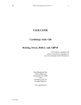
Case 1: A Simple scenario
The user has already generated their mesh before calculation and wants to visualise it before running
their simulation. So the scenario will be:
1) Translate the mesh file to Vista format.
2) Send Vista data to the Visualisation tool.
MRI Raw Data
Mesher
Visualisation Tool
Figure 1: Simple Scenario Communication
5
SimBio Deliverable: D6.b
Case 2: A More Ambitious Scenario
An ultimate post-project end-user scenario in the case of meniscus replacement might look like the
following:
1. The patient’s knees are scanned at some scanning facility and the data is inserted
into the SimBio environment.
2. At the clinic of the patient’s doctor, which may be in the same building, or across
the street, or (as is often the case in Germany) across town, a doctor’s assistant
uses SimBio to access the scanned data and prepare a mesh of the patient’s knee.
3. The doctor’s assistant then selects a standard mesh for the meniscus prosthesis
and instructs SimBio to prepare a simulation of the knee movement.
4. SimBio sends the data to a computing centre where the simulation is performed.
Once it is completed, the doctor’s clinic is notified of the results.
5. The doctor then examines the simulation results and makes any recommendations
to his or her assistant regarding changes to the selection of prosthesis design.
While this scenario may sound far-fetched today, it is in the realm of what is possible within the next
decade. In addition to the requirements already mentioned, this scenario yields one further point
which need to be taken into consideration: Namely, not all users will be experts in the field of bionumerical simulations, or Ph.D. level scientists, or even computer experts, therefore the SimBio
environment must be easy to use.
6
SimBio Deliverable: D6.b
WP6 Prototype Definition
Description
After a lot of discussions with every partners involved in the SimBio project, depending on their
needs, it has been decided the following.
Partners asked WP6 to develop a simple design concept for the Component Interaction.
The basic idea was to have something with a complexity similar to shell scripts but easier for the
novice to use.
Furthermore, the SimBio environment should be comprised of two sites:
Ø At the first site, the complete pre-computing will be performed. To be more precisely: independent
on the employed tools and their interactions, the output of this phase is the corresponding mesh.
We will call this phase local.
Ø The other site, we call it a compute server or remote site, is responsible for performing the
designated simulations. The output of the compute server is the final visual data set.
All those users who do NOT intend to use these dedicated compute server have to take care about the
simulation phase themselves.
To generate the SimBio request that will describe the user’s simulation, we will provide to the enduser an editor; This editor will be used to define the user needs (application and parameters) and then
will
generate
a
SimBio
Request
(or
Simulation
request)
File.
This editor will be called ‘SimBio Scenario Editor’ and developed by ESI.
The contents of the Request will be analysed by a special application. This program launches the
programs sequentially according to their appearance in the request. It is also in charge of initiating the
calls for the compute server related part. This application is called ‘SimBio pilot’ and was developed
at NEC. The implementation of the compute server functionality has also been taken over by NEC.
The File format used for this Simulation Request file is XML (eXtended Marked Language) format.
You will find short descriptions of the SimBio Request XML file in the following sections. There is
also an XML Simulation example file with the corresponding Document Type Definition (DTD) file at
the end of the document. For more information about XML format, please consult
http://www.xml.org/, http://www.w3.org/XML/ or http://xml.apache.org/index.html.
7
SimBio Deliverable: D6.b
Fit to predefined requirements
In the previous deliverable D6a 1 , we listed some requirements for this WP6 such as Genericity,
Heterogeneity, Security / Authentication in Distributed Environments, User Interaction and Data
Reuse.
We could see that the previous description of the current work done inside WP6 continue to fit with
this requirement.
Ø Genericity: we will see in the following description of work that adding new components in this
prototype will be as simple as possible. Facility to do a such thing remains one of the main
objective of the future job.
Ø Heterogeneity: same remark. Components of SimBio environment will come from a lot of partners
in very different platform and should be included easily.
Ø Security / Authentication in Distributed Environments: In the local phase, no security problems
could occur. In the remote phase, use of securized option inside Corba will assure this security.
Ø User Interaction: The end-user will be completely responsible of its simulation through the
SimBio Scenario Editor. He is also responsible of tools he wants to use and of course on the way
to use it.
Ø Data Reuse: For the moment, no connection to result database will be done; the only reuse of data
that we managed will be reuse of already existing result file (managed by the end-user).
Fit to predefined constraints
Also, in the previous deliverable D6a, we listed some constraints for this WP:
•
Not all applications that we want to inter-operate have their source code available, which means
we have to find a solution to create some kind of encapsulation above the executable.
Ø By the fact we will use direct calls to application from the SimBio-pilot as we could do with
scripts, no needs to source code is necessary. Only executable and users’ manual are necessary
to add new application inside SimBio environment.
•
The SimBio applications work on different platforms like Unix, Linux or Windows based systems.
Ø By the fact that we will work on local machine, end-users will be responsible to get the correct
application he wants to use (platform and version). If he wants to use remote version of a
given application, he will be responsible for writing remote access using script for instance or
any other solution. Since we cannot provide solutions for every local environment and we
won't be granted with sufficient access permissions at large independent computing centres,
we will exclusively focus our "remote site" environment work on compute servers that we are
able to control ourselves.
•
Not all applications run at the same site. They are located at many different sites (on remote
computers) not close to each other.
Ø Same remark than the previous constraint.
•
Not all applications have a GUI so we have to execute the application directly or create a simple
wrapper GUI.
Ø Each application must be able to run with command line options; then the SimBio Scenario
Editor will provide GUI to allow settings all parameters of every application.
1
Component Interaction (CI) Report
8
SimBio Deliverable: D6.b
XML Simulation Request File Description
You will find one XML Simulation example file on the Annexes in this document and the
corresponding Document Type Definition (DTD) file.
The XML Simulation Request file contains the following information in addition to the requested
XML heading:
1. Simulation Request ID.
2. User Environment description:
§ Working directory,
§ Log file,
§ Notify address: person to prevent when simulation is finished.
3. Request Sequence: list of application to be run.
4. Each Request (called application) contains the following parameters:
§ Application name (command name).
§ Standard input filename.
§ Standard output filename.
§ Standard error filename.
§ Command line parameters; each parameter is made of option name (command line name) and
corresponding value.
Some additions will be made during the development phase if necessary.
9
SimBio Deliverable: D6.b
User’s Manual
SimBio Scenario Editor
Description
This is a simple GUI application, which allows creating scenarios by selected desired components
(application), to define application parameters and then execute the scenario through the SimBio Pilot.
The ultimate goal of this GUI should be to provide each class of users a means to automatically
generate the corresponding SimBio request. The SimBio request describes the complete pre and/or
post processing. The ideal GUI should be capable to reflect a dynamically changing pool of services.
However, since we are aware of the fact, that the generation of such a tool is extraordinary complex on
the one hand, and imposes a significant overhead to the majority of (static) cases on the other we
propose to deal with this issue in the following way:
1. Step
1
(currently
done):
Development of a GUI for controlling the fixed set of tools which currently constitute the
backbone of the project. The GUI should generate an XML file that serves as a control file for pre
and/or post processing. Thus, every user gets an elegant and efficient tool for driving the
environment.
2. Step
2:
Due to the fact that we cannot assume that the set of tools remains constant in the future, a
professional GUI should be able to dynamically adapt itself to changes. For this advanced tool we
propose to base the generation of the GUI on an XML file containing the explicit descriptions of
all participating tools. However, the development of this GUI should NOT be mandatory for the
scope of WP6.Anyway, the reflection about this step has already started at ESI and depending on
the job to do during the next month of the project (improvement, debugging, modifications,
partners need after the evaluation phase), it will be possible to achieve this step.
Technical Description
This application is written in C++ and used QT library (http://www.trolltech.com/products/index.html)
to define GUI and Xerces-C (http://xml.apache.org/xerces-c/index.html) for XML read and write.
§
Qt is a GUI software toolkit. Qt simplifies the task of writing and maintaining GUI (graphical
user interface) applications. Qt is written in C++ and is fully object-oriented. It has everything you
need to create professional GUI applications. And it enables you to create them quickly. 2
§
Xerces-C is a validating XML parser written in a portable subset of C++. Xerces-C makes it easy
to give your application the ability to read and write XML data. A shared library is provided for
parsing, generating, manipulating, and validating XML documents. Xerces-C is faithful to the
XML 1.0 recommendation and associated standards (DOM 1.0, DOM 2.0. SAX 1.0, SAX 2.0,
Namespaces), The parser provides high performance, modularity, and scalability. Source code,
samples and API documentation are provided with the parser. For portability, care has been taken
to make minimal use of templates, no RTTI, no C++ namespaces and minimal use of #ifdefs. 3
2
3
Official Description – Please have a look on official WEB site for more information.
Official Description – Please have a look on official WEB site for more information.
10
SimBio Deliverable: D6.b
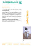
SimBio Scenario Editor Main Interface
Figure 2: SimBio Scenario Editor – Main Window
Each component is represented with a simple square and the component name. We hope to replace this
with
application
icons
as
soon
as
they
will
become
available.
Selected component appears in red, others in green.
The first toolbar (on the left) contains some tool buttons with important (often-used) functionality such
as New, Open, Save, Print, Properties Run and Help.
The second toolbar (on the right) contains list of available components. It is exactly the same contents
than Insert Menu.
11
SimBio Deliverable: D6.b
File Functionality
Here is the list of all file menus available from this SimBio Scenario Editor.
Figure 3: File Menu
♦ New: Create a new empty scenario. A new empty Scenario Window appears and becomes the one
active. Next calls to save, save As, Print, Close, Edit menus and Insert menus will concern this
new active window.
♦ Open: Open a file selector where user can select a file. Then this file is loaded and a new window
will appear to display its content. If the load operation failed, an error message is displayed and no
new window is created.
♦ Save: Save the current XML scenario file. If no save has already been done, a name and location
are asked and the new file is created, otherwise the current file is updated.
♦ Save As: A name and location are asked and the new file is created.
♦ Print: Not yet implemented. We are currently thinking about that function: print the XML file,
print the graphical part of the interface or something else. To be discussed.
12
SimBio Deliverable: D6.b
♦ Properties: Display the properties (filename, simulation name, working directory, error log file and
notify address) of the current simulation request. See below.
Figure 4: Simulation Request Properties Dialog
♦ Run: Call the SimBio Pilot to run the current simulation. If modifications have been done, save
function is called before. Default called application is the one defined with environment variable
called ‘SIMBIO_PILOT_PROG’, if no variable is defined, script ‘simbio-pilot.csh’ is called. The
only parameter to this application or script is the name of the XML Simulation Request file.
♦ Close: If modifications have been done, save function is called and the current window is closed,
otherwise current window is simply close.
♦ Quit: Same than close function but applied to all windows of the editor. Once all windows are
closed, the application is exiting.
13
SimBio Deliverable: D6.b
Window Functionality
Functions used to manage SimBio Scenario Editor windows.
Figure 5: Windows Menu
♦ Cascade: All existing scenario windows are displayed one by one above the others.
♦ Tile: All existing scenario windows are displayed one by one beside the others.
♦ Window 1…n: The selected window is displayed in front of the others and becomes active. The
red sign shows the current active window.
Help Functionality
Functions used to manage SimBio Scenario Editor help.
Figure 6: Help Menu
♦ About: Display a dialog with a very simple definition (name, short description, authors and
version) of the SimBio Scenario Editor.
♦ About QT: Display a dialog with a simple definition remembering QT usage.
♦ What’s this: The current icon becomes “?”. Click on a menu or a button to display a short
description of its functionality.
14
SimBio Deliverable: D6.b
Applications functionality
Here is the list of functions used to manage SimBio Scenario Editor components.
The user could choose the components he want to use during its simulation; he is also requested to set
every parameter. Once the user selects one component, the corresponding property panel is displayed
and needs to be validated. If the current component is already inserted in the current simulation, the
operation is cancelled.
For the moment only 4 applications are available: vgrid, vsegment, uif3 and drama-sim.
Figure 7: Insert Menu
Here are each Properties Dialog Box the user has to fill to define component parameters that
correspond to the current status of development for each application. See below images to have more
information on this parameter that corresponds to the command line option of the described
component.
15
SimBio Deliverable: D6.b
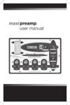
Figure 8: vgrid (Mesh Generator) Component Properties Panel
16
SimBio Deliverable: D6.b
Figure 9: vsegment (segmentation) Component Properties Panel
17
SimBio Deliverable: D6.b
Figure 10: uif3 (Inverse Toolbox) Component Properties Panel
Figure 11: drama-sim Component Properties Panel
18
SimBio Deliverable: D6.b
Applications Management
Functions used to manage SimBio Scenario Editor editing.
Figure 12: Edit Menu
♦ Undo: Not yet implemented. Should cancel the last operation done (only one level).
♦ Cut: Remove selected component from the current simulation but keep it in the SimBio Scenario
Editor clipboard.
♦ Copy: Copy selected component from the current simulation to the SimBio Scenario Editor
clipboard.
♦ Paste: Copy SimBio Scenario Editor clipboard to the current simulation.
♦ Deselect: Remove component selection. In this case, Cut and Copy becomes no more available.
♦ Properties: Open the Properties Panel Dialog corresponding to the selected component.
19
SimBio Deliverable: D6.b
Adding new components
To be really generic, users must be able to easily add new components inside the SimBio Scenario
Editor. To do such as thing, we propose to deal with this issue in the following way:
1. Adding new components by source code modification.
2. Reading components definition inside configuration file (probably XML format too).
For the moment, only step 1 is available, the SimBio Scenario Editor contains a fixed number (4) of
components and we have defined a list of steps to do to add a new component. This ‘adding manual’
has already been tested successfully when adding the fourth component (Inverse Toolbox component).
Step 2 will be the next emphasis work and will be defined in the ‘Future Plan’ section.
For the moment, to add new component by source code modification you have to follow the next 14
steps:
You can also have a look on source code and search for vgrid for instance to see how this component
has been added. Please use variables name, files name, functions name, …, which contain the name of
the component you add to be able to find it again easily in the source code.
1. Create properties dialog box using QT designer. See examples in “designer/*.ui”. You can also
created by hand but it will be more difficult.
2. Add references into Makefile and designer/Makefile.
3. Create a new simple icon for menus (see “application?.xpm” in “resources/”).
4. Add "#include "application?.xpm" (or the name you choose for your icon) in
“SimbioWindows.cpp”.
5. Add menu button in “SimbioMainWindow::createSimulationMenu”.
6. Add toolbar button in “SimbioMainWindow::createSimulationToolbar”.
7. Add function “SimbioMainWindow::addApplication?” in “SimbioWindows.hpp”.
8. Add function “SimbioMainWindow::addApplication?” in “SimbioWindows.cpp”.
9. Add function “SimbioDocumentWindow::addApplication?” in “SimbioWindows.hpp”.
10. Add function “SimbioDocumentWindow::addApplication?” in “SimbioWindows.cpp”.
11. Add new application parameters in “SimbioSimulation::initializeKnownApplications”.
Be careful, don't forget to update “SimbioSimulation::nbKnownApplications” in this function.
12. Add new type of application (EN_ApplicationKind) in “SimbioApplication.hpp”.
13. Add new case in “SimbioApplication::setType”.
14. Add
new
case
in
“SimbioApplication::updateDialogFromApplication”.
Be careful, don't forget any widget.
15. Add
new
case
in
“SimbioApplication::updateApplicationFromDialog”.
Be careful, don't forget any widget.
20
SimBio Deliverable: D6.b
Simulation Phase
General Overview
As already described above the SimBio partners agreed to restrict the SimBio environment to a
simplified 2-way model. The first part of this model constitutes the local environment. Here all nonsimulation tools are installed and controlled by our SimBio Editor. The other part of this model is the
so called remote or compute server site. Many discussions have been held about the way local and
remote tools should interact within medical environments (cf. D6a). Finally we agreed on using the
middleware layer CORBA to handle the required data exchanges and authorisation steps. Since the use
of CORBA imposes a client/server logic onto our environment, we have to install server daemons on
the compute server site, which permanently listen for incoming SimBio requests. Apart from very few
exceptions, the vast majority of parallel systems are under the control of management programs. One
central part of these suites is the job scheduler. The SimBio server has to interact directly with the
scheduler for starting simulation requests and receiving information about the current job status
(queued, running, terminated) . Since the server has to do these actions in name of all legal SimBio
users, it needs additional permissions for their execution. However, it is very unlikely that external
computing centres would allow the installation of such daemons. Furthermore, the interaction
possibilities with classical batch queuing systems, e.g., NQS, are rather limited. Thus, it is only
feasible to provide a comfortable and user friendly compute server environment on systems that are
fully under our control. The negative impact on SimBio partners is that it’s only possible to use the
NEC’s PC-cluster for their simulation automatically. If they require other platforms instead, they will
get no further support from the “generic environment”. However, if partners would install compatible
clusters, they could straightforwardly port our compute server related software to them.
Introduction
Depending on the local security environment under which a user is working, the simulation part
consists of either one or two client server pairs. The first client program is responsible for transferring
to the target machine the description of the simulation, the so called request descriptor (RD), along
with the corresponding mesh/grid file. On the target machine a servant listens for matching incoming
requests. It checks the validity of the RD and, if all security aspects are successfully matched, stores it
in a database. The status of the transmission, success or error value, is returned to the client program.
On those sites that allow for callbacks, an additional server program is launched in the local
environment of the user. Its purpose is to process the incoming result data from the simulation and to
store it in a certain directory. The server on the simulation site launches an appropriate client for
handling the transfer. If security restrictions on the user site prohibit the automatic exchange, users are
in charge of ftp-ing the data on their own. Since big time differences may occur between the initiation
of a request and it’s completion, an e-mail will provide information on the termination status of the
request to the user.
Implementation Design
Request Initiation
The Pilot invokes the client program after having successfully generated the mesh/grid file. It simply
passes the name of the grid file and additional control values as command line parameters to the
executable. The client tries first to transfer the RD to the server. Currently the RD consists of the
following IDL entries:
21
SimBio Deliverable: D6.b
struct SimReq_ {
Account user;
Account password;
Path email;
FileName mesh;
Path workdir;
Path targetdir;
short time;
short procs;
};
Listing 1: RD’s Idl Representation
The call might fail due to several reasons. On the one hand, the complete compute server service may
not be active. Here, the client is unable to connect to the naming service or the actual SimBio server
due to hardware/network problems. Another possibility would be a rejection of the service due to
invalid access permissions. While in the first case the users have to postpone their actions, in the latter
one they could check their user/password pairs and re-try or ask the SimBio service administrator for
further information.
Request Storing
The server program running on a system in the parallel compute server environment enters some data
from the RD into a relational database ( currently MySQL). The delivered user and password entries
are used to validate the permission for inserting into a table. Furthermore the values for requested time
and procs are checked whether they are in allowed range. If all relevant parameters are matching the
requirements, the actual insertion will be done. After the successful completion of this first
transmission phase, the client starts to send the (large) binary file. The servant in charge receives this
file chunk by chunk and stores it into the targetdir. If no problems occurred a special flag is updated in
the corresponding line of the database table, indicating the completeness of the simulation request. At
this point the client program terminates and the established network connection shuts down.
Request Execution
The job scheduling system is instrumented to check periodically the contents of the SimBio request
database. If it detects a simulation request ready for execution and the required resource contingents
are available, it will automatically schedule the request for a batch queue. Every user gets an e-mail
acknowledgement at starting and termination time of the job. In those cases where automatic transfer
of result data is possible, the scheduler will invoke the corresponding client program. The request will
be taken out of the request table and shifted to an accounting table. The information stored here could
be taken for various things, e.g., statistics on machine usage or preparation of invoices.
Security
For the data-exchange between user site and the compute server, we use the SSL plug-in from
CORBA. This gives as currently a 128-bit encryption security. If user decide that the sensitivity of
their data is low, e.g., test or junk data, encoding and decoding phases can be omitted for performance
issues.
Status of Prototype
The first integrated simulation program is the HEAD-FEM FE code. It expects a mesh file, originally
generated by the vgrid utility and later partitioned with the DRAMA tool, as input parameter. Both,
the partitioning program and the simulation code run in parallel on the same number of processors,
which allows to do just one resource allocation. A predefined batch script is passed to the scheduler
that fetches the mesh file and invokes the DRAMA tool on it. If this could be successfully completed,
the actual simulation is carried out.
22
SimBio Deliverable: D6.b
SimBio Pilot
Description
The SimBio-Pilot executes the SimBio requests. Normally, as mentioned above this program will be
started automatically by the so-called SimBio Scenario Editor, however, if the user has an appropriate
XML file, then it can be started on the command line as: simbio-pilot file.xml.
Functionality
The SimBio-Pilot uses the Apache Xerces program to parse the XML request file. It then extracts the
individual commands which are part of the complete request and executes them sequentially in the
order defined by the XML request file. Once the request sequence is completed an-email message is
sent to the user containing a status report on each individual request. In addition, the status messages
are written to the log file specified by the user in the XML request file.
23
SimBio Deliverable: D6.b
Release Notes
SimBio Scenario Editor
•
24.04.2001: Version 0.1.1 fixes the following bugs and errors:
1. Adding new application called uif3, Inverse Toolbox application, with corresponding
properties panel.
2. ‘raw data’ used for testing was removed.
3. ‘Memory Fault’ core dumped with ‘New’ menu in QT static version.
4. ‘Memory Fault’ core dumped when inserting a vgrid application within an empty simulation.
5. Call to SimBio Pilot is now done using environment variable called
‘SIMBIO_PILOT_PROG’ instead of calling directly a script. If this variable does not exist,
default value 'simbio-pilot.csh’ is called. The parameter is still the scenario XML file.
•
15.04.2001: Beta Version 0.1.0 is completed. The SimBio Scenario Editor incorporates the
following features:
1. It contains 4 applications (rawdata, vgrid, vsegment and drama-sim). Each application has its
own properties panel that allows user to set application parameters.
2. Following functions are currently working: New/Open/Save/Save As, Properties/Run,
Close/Quit, Cut/Copy/Paste, Deselect/Properties and Insert application1 to 4. It is able to
manage several scenarios at the same time and all windows manipulation (tile, cascade and so
on) from QT are available.
3. Following
functions
that
are
not
currently
implemented:
Print:
nothing
done
for
the
moment.
- Undo: not yet finished.
4. Binary versions are available for the following operating systems:
1. SGI IRIX 6.5 with QT Dynamic or QT static.
2. SUN OS 5.5 has been tested once but have to be redone.
24
SimBio Deliverable: D6.b
SimBio Pilot
•
11.04.2001: Version 0.1.1 fixes a bug that can occur due to certain incompatibilities between
versions 18-12-2000 and 24-10-2000 of the ‘simbio-request.dtd’ files.
•
01.04.2001: Beta Version 0.1.0 is completed. The SimBio-Pilot incorporates the following
features:
* Reads XML files covered by the ‘simbio-request.dtd’ version 18-12-2000 or 24-10-2000.
* Executes the user's request in exactly the order given.
* Creates a log file containing a list of all requests along with any error messages.
* Notifies the user via e-mail when the entire request sequence has finished.
* Binary versions are available for the following operating systems:
3. SGI IRIX 6.5.
4. Linux 2.2.
(At the moment only dynamically linked versions are available for SGI systems.)
25
SimBio Deliverable: D6.b
Future Plan
SimBio Scenario Editor
First of all this editor will be distributed to partners involved in the project that they can evaluate it.
Depending on their comments, the following list of priority could be modified.
Anyway here are future developments, in order of priority; we would like to emphasis on in the near
future:
1) (high) Adding work package ST4.2 application, called uif3, that is not yet fully achieved.
2) (high) Manage automatically adding new components into Editor. This will probably be done
using some kind of XML configuration file that described each new component.
Each new component will be described at least with the following Information:
• Application name (executable name).
• Application description.
• Application parameters. For each parameter we need at least the following information:
• Parameter description.
• Command-line name (like “–np” for instance).
• Type of parameter: input, output, option or help.
• Type of parameter value (filename, string, Boolean, integer, real, enumerated,
range,…). This information will be used to generate an automatic interface for the
component.
• Default value.
• Application small icon to be used for toolbar.
• Application large icon to be used for drawing.
This evolution needs to be discussed again to be sure to do not forget any important information.
These informations will be read and used to generate a simple Dialog box that allows user to set
every parameters of his new component. We cannot expect to have an extraordinary beautiful dialog
box but only simple one using some kind of simple QT widget such as label, text, slider, checkbox and
list box.
3) (medium) Changing application menus (toolbar) by using 16x16 'icons'. Needs to get icon for
each component that is part of the SimBio Scenario Editor.
4) (low) Changing application drawing by using 100x100 'icons'. Needs to get icon for each
component that is part of the SimBio Scenario Editor.
5) (medium) Create a configuration file (XML again?) that could allow user to change SimBio
Scenario Editor parameters such as user name, user email address, SimBio pilot name, colour,
widget size, widget position, XML reading and writing option (with or without DTD for
instance),...
26
SimBio Deliverable: D6.b
Compute Server Development
In the second year we will integrate the missing simulation applications into our compute server
environment. Another important issue is the implementation of solutions for the interaction of
applications and the inverse tool box, which has not been addressed yet.
Since the transfer of huge binary data files between user and compute server site can become a
significant bottleneck, possibilities for optimising the transfer should be considered.
27
SimBio Deliverable: D6.b
Annex 1: XML Simulation Request Example File
This simulation request called ‘New_Simbio_Simulation‘ is made of 4 application: vgrid, vsegment,
uif3 and drama-sim; each application contains an important number of parameters (called option).
<?xml version="1.0"?>
<!DOCTYPE SimBio-Request SYSTEM "simbio-request.dtd">
<SimBio-Request id="New_Simbio_Simulation">
<user-environment>
<working-dir>.</working-dir>
<log-file>./logfile</log-file>
<notify>[email protected]</notify>
</user-environment>
<request-sequence>
<request>
<command>VSegment3D</command>
<command-line-options>
<option name="-in">./out1</option>
<option name="-out">./out2</option>
<option name="-nc">4</option>
<option name="-correct">1</option>
<option name="-opt">0</option>
<option name="-lambda1">500</option>
<option name="-lambda2">2.00E+06</option>
<option name="-min">5</option>
<option name="-max">33</option>
</command-line-options>
</request>
<request>
<command>VGrid</command>
<command-line-options>
<option name="-in">./out2</option>
<option name="-out">./out3</option>
<option name="-elem">tetra6a</option>
<option name="-file">gridfile</option>
<option name="-format">kaskade</option>
<option name="-min">5</option>
<option name="-max">7</option>
<option name="-smooth">marching</option>
<option name="-shift">0.05</option>
</command-line-options>
</request>
<request>
<command>uif3</command>
<command-line-options>
<option name="-in">./out3</option>
<option name="-out">./out4</option>
<option name="-ls">On_Cortex</option>
<option name="-lh">BEM</option>
<option name="-lis">L2</option>
<option name="-lit">Truncated_SVD</option>
<option name="-gs">On_Cortex</option>
<option name="-gh">BEM</option>
<option name="-ms">On_Cortex</option>
<option name="-mh">BEM</option>
<option name="-num">4</option>
<option name="-df">Moving</option>
<option name="-dh">BEM</option>
<option name="-di">Truncated_SVD</option>
<option name="-do">Simplex</option>
<option name="-dc">MSError</option>
<option name="-igs">0</option>
<option name="-sveb">0</option>
<option name="-itl1">0</option>
<option name="-nls">On_Cortex</option>
<option name="-nlh">BEM</option>
28
SimBio Deliverable: D6.b
</command-line-options>
</request>
<request>
<command>Drama-Sim</command>
<command-line-options>
<option name="-f">./out4</option>
<option name="-out">./out5</option>
<option name="-np">8</option>
</command-line-options>
</request>
</request-sequence>
</SimBio-Request>
29
SimBio Deliverable: D6.b
Annex 2: Corresponding DTD4 file: ‘simbio-request.dtd’
<?xml version="1.0" encoding="UTF-8"?>
<!-- ............................................................... -->
<!-- SimBio Request DTD ............................................ -->
<!-- ............................................................... -->
<!-PURPOSE:
This DTD was developed within the SimBio project. It is intended
to define a user request on the environment.
CHANGE HISTORY:
The list of changes appears at the end of the DTD.
-->
<!-- A SimBio request consists of a "user-environment" element and
a "request-sequence" element. Additionally, each SimBio request
an ID which should be universially unique.
-->
<!ELEMENT SimBio-Request (user-environment,request-sequence) >
<!ATTLIST SimBio-Request id ID #REQUIRED>
<!-- The "user-environment" consists of a working directory, a log file,
possibly stderr and stdout files and a an e-mail address of the
user to be notified when the request has completed.
-->
<!ELEMENT user-environment (working-dir,log-file,notify) >
<!ELEMENT working-dir (#PCDATA) >
<!ELEMENT log-file (#PCDATA) >
<!ELEMENT notify (#PCDATA) >
<!-- The request sequence consists of one or more requests that are to be
executed in the order in which they appear in the file.
-->
<!ELEMENT request-sequence (request+) >
<!-- Each request contains all the information needed to run the
specified command.
-->
<!ELEMENT request (command,stdin?,stdout?,stderr?,command-line-options*) >
<!ELEMENT command (#PCDATA) >
<!ELEMENT command-line-options (option*) >
<!ELEMENT option (#PCDATA) >
<!ATTLIST option
name CDATA #REQUIRED
type CDATA #IMPLIED>
<!ELEMENT stdin (#PCDATA)>
<!ELEMENT stdout (#PCDATA)>
<!ELEMENT stderr (#PCDATA)>
<!-- ............................................................... -->
4
Document Type Definition
30
SimBio Deliverable: D6.b
<!-- Change history ................................................ -->
<!-#18-12-2000: kohring
#
Ammended the "stdin, stdout and stderr" definitions to be
#
consistent with the definition for "logfile"
#07-12-2000: janvrais
#
Replaced 'request*' with 'request+' in 'request-sequence' definition.
#
This prohibits one from generating XML files without a request.
#24-10-2000: kohring
# - initial version
-->
31