1
,__e,...
..- .--'~
---= '--
.--
---.
'V
--"
@
PRO 5000
Professional
MobileCB radio
:[
-
-..-.-..
J
br-
-==::::
<::
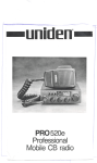
Introd uction
Welcome to the world of sophisticated, state-of-the-art
CB radio communi-
cations. YourUniden PRO5000 represents the mostadvanced mobileradio ever
designed for use in the Citizens Band Radio Service. It willoperate' on any of the 40
,~M frequencies authorized by the Department of Communications. Your PRO
5000 features a superheterodyne circuit with PHASELOCKEDLOOP techniques
to assure precise frequency control. This radio has been type accepted and certified by the DOC
Warning
Before transmitting with your transceiver, you must obtain clDepartment of Communications (D.O.C) Citizens Radio Licence. Obtain an application form, from
the D.O.C Before completing the form you should read the conditions governing
the licensing and operation of the CR.S. (D.O.C brochure RB 14). This brochure
also can be obtained from the D.O.C After completing the application form, mail
it with the appropriate fee to the Superintendant Regulatory of Licensing in the
State or territory in which the station will be operated.
Connecting
the Power Cords
With regard to the connection of the power cords, it may be possible or desirable
to connect the red lead (for negative ground systems) or the black lead (forpositive
ground systems) to the ignition switch accessory terminal so that the radio isautomatically turned off when the ignition switch (key) is turned off.
Alternately, the power lead may be connected to an available terminal on the fuse
block or even to a point in the wiring harness. Care must be taken, however, to
guard against a short circuit condition. When in doubt, please contact your vehicle dealer for specific information about your vehicle.
J
1:
T
- -.-- -
1-
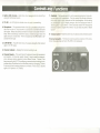
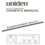
1. Built-in ANL Circuitry - Help reduce harsh background noise caused by a
variety of interference sources.
2. TX LED - An LEDlights to indicate when the radio is transmitting.
3. Microphone - The operational mode of the CBis controlled by the push-totalk switch on the mic. Press the switch to activate the transmitter and disable
the receiver. Release the switch to enable the receiver and disable the transmitter. When transmitting, hold the mic about 2 inches from your mouth and
speak clearly in a normal voice. The mic included with the PRO 5000 is a detachable electret type.
4. SjRF METER - This LEDmeter shows the relative strength of the received
signal or the RF output.
5. Channel
Indicator
- Displays the channel currently in use.
6. Channel Selector - This switch selects the desired channel for transmission
and reception. All channels, except channel 9, may be used for communications between stations operating under different license. Channel 9 has
been reserved by the D.O.C for emergency communications involving the immediate safety of individuals or the immediate protection of property. Channel
9 also may be used to render assistance to a motorist. This is a D.O.C rule and
applies to all operators of CB radios.
1. SQUELCH- The Squelch conrrol is used to eliminate background noise during the absence of a transmission. Turn the control fully counter clockwise,
then slowly rotate it back, clockwise until all noise disappears. At this setting
any transmission must be slightly stronger than the background noise to
"Break Squelch" or to be heard. Further clockwise rotation will increase the
threshold at which a signal will be heard. You can select any level to "Break
Squelch"
8. Volume Control - Rotate clockwise to turn radio on and to increase volume.
Antenna Connector - This female connector permits connection of the transmission line cable male connector (PL-259)to the transceiver.
---
0
eration
Operating Procedure to Receive
1. Besure that the power source, antenna and microphone are properly connected.
2. Turn the unit on by rotating the volume control clockwise.
3. Set the channel selector switch to the desired channel.
4. Set the volume control to a comfortable listening level.
5. Listen to the background noise from the speaker. Turn the squelch control
clockwise until the noise disappears (no signal should be present). Leave the
control at this setting. The squelch is now properly set. The receiver will remain quiet until a signal is actually received. Do not advance the control too
far, or some weaker signals will not be heard.
Operating
Procedure
to Transmit
1. Be sure the operator has read and understands D.G.C rules and regulations
prior to operating the transmitter.
2. Select the desired channel for transmission.
3. 'fthe channel isclear, depress the push-to-talk switch on the side of the microphone and speak in a normal voice.
CAUTION: The transceiver Voltage Standing Wave Ratio (V.S.W.R.)measurement must be performed prior to the use of the transmitter. A "V.S.W.R." ratio in
excess of 2: 1 may damage the transmitter. Please check your SWRreading frequently by using an SWRmeter.
Preventative
Maintenance
At six to twelve month inteNals, the following system checks should be made:
1. Check the Voltage Standing Wave Ratio (V.S.W.R.)
2. Inspect all electrical connections.
3. Inspect antenna coaxial cable for wear.
4. Inspect all screws and other mounting hardware.
]
I
!
t
--- --- - - -
'r-
Installation
Plan the location of the radio and microphone bracket before starting installation.
Select a location that is convenient for operation and does not interfere with the
driver or passenger in the vehicle. The radio should be securely fastened to a solid
surface using the mounting bracket and self-tapping screws which are provided.
Mobile Antenna
Since the maximum allowable power output of the transceiver is limited by the
D.O.C, the antenna isa very important factor affecting transmission distance. It is
for this reason that we strongly recommend that you install only a quality antenna
in your new CB radio system. You have purchased a superior quality transceiver.
Don't diminish its performance by installing an inferior antenna.
Only a properly matched antenna system will allow maximum power transfer from
the 50-ohm transmission line to the radiating element. We recommend that you
use an SWRmeter when installing your antenna. Set your PRO 5000 to channel
20 and make adjustments to the antenna until the meter reads as close to 1as possible. YourUniden dealer is qualified to assist you in the selection of the proper antenna to meet your application requirements.
For automobile installation, the whip antenna may be used with good effect. The
most efficient and practical installation is a full quarter wave whip antenna
mounted on the rear deck or fender top, midway between the rear window and
bumper.
t\ short "loaded" whip antenna is more convenient to install on your automobile,
although the efficiency is less than a full quarter wave whip antenna.
For marine installation, consult your dealer for information regarding an adequate
grounding system and prevention of electrolysis between fittings on the hull and
water.
Ground
Information
Most newer cars and small trucks use a negative ground system, while some older'
cars and some newer larger trucks may use a positive ground system. A negative
ground systemisgenerallyidentifiedbythe "-" battery terminal being connected
to the vehicle motor block, but ifyou cannot determine the polarity of your vehicle, consult your vehicle dealer for information.
NOTE: This radio may be installed and used in any 12-volt DC negative or positive
ground system.
Negative
~
Ground System
Ifyou are operating on a negative ground system, connect the red DC power cord
from the radio to the positive "+" battery terminal or other convenient point and
connect the black power lead to the chassis orvehicle frame, orthe negative "-"
terminal of the battery.
Positive
Ground System
If you are operating on a positive ground system, connect the black DC power
cord fromthe radioto the negative "-" battery terminalor other convenient point
and connect the red power lead to the chassis orvehicle frame, orthe positive "+"
terminal of the battery.
<::
F--'"
=
r~--~-
-
-===
:=::::Y-..
--=+-.,
I
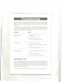
Channels:
Frequency Range:
Frequency Control:
Frequency Tolerance:
Operating Temp.:
Microphone:
Input Voltage:
Current Drain:
40 AM
26.965 to 27.405 MHz
Phase Locked Loop '(PLL)synthesizer
:!:0.005%
-30°C to +50°C
Plug in type: electret
13.8 VDC nom. (+ or - ground)
TX:full mod., 1.7A
RX:with max audio output, 1.7A
4- 9/ 16"W X 6 _35 / 64 "0 X 1-13/ 32 "H
1.61bs.
UHF, SO-239
Indicates relative RFoutput and received signal strength
Size:
Weight:
Antenna Connector:
LEDMeter:
TRANSMITTER
Power Output:
Modulation:
Freq. Response:
Output Impedance:
RECEIVER
Sensitivity:
4 watts
Class B amplitude modulation
300 - 2500 Hz
50 ohms, unbalanced
Selectivity:
Image Rejection:
I.F. Frequency:
Automatic Gain Control:
Squelch:
Audio Output Power:
Freq. Response:
Distortion:
Internal Speaker:
0.7pV for 10dB; (S + N)/N typical (limit:
1.2pV)
6dB a 7KHz, 70dB a 10KHztypical
80 dB typical
Double Conv~rsion Superheterodyne
1st 10.692 MHz
2nd 450 KHz
(AGC):less than 10dB change in audio output for inputs from 10 to 50,000 microvolts
Adjustable; threshold less than 1pV
7 watts max. into 8 ohms
300 to 2000 Hz
less than 10% at 4 watts, 1000Hz
16 ohms,S watts round
Specifications and features are subject to change without notice.
---.--
~
-h.--
-
1
L
l
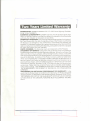
Troub.leshootin
Ifyou r PRO5000 is not perform ing up to you r expectations, please try these simple
steps. Ifyou still cannot get satisfactory results after reading this manual and following the trouble shooting steps, please call the Uniden Australia Pty. Ltd. at
599-3355.
Ifyou determine that seNice is necessary, contact your local dealer or pack the unit
in its original carton and send it along with a brief, concise description of the problem, your name, address, phone number, and a copy of the original purchase receipt to the address listed in the warranty.
TROUBLE
CHECK
Unit will not turn on.
No power.
1. Check power cord and all
connections.
2. Check power cord fuse.
3. Check vehicle electrical system.
Poor reception
1. Check and adjust Squelch.
2. Check antenna system, cabie and connectors.
3. Check operation mode of the radio.
Weak transmission
1. Check antenna system, cable and connectors.
2. Check antenna grounding.
3. Check for corrosion on connectors.
Servicing your CB
Technical information, diagrams and charts will be provided upon request. It is
the user's responsibi/ityto see that this radio is operating at all times in accordance
with the O.O.C Citizens Radio SeNice regulations. We highly recommend that
you consult a qualified radiotelephone technician for seNice and alignment ofthis
radio. When ordering parts, it is important to specify the correct model number
and serial number of this radio.
Please refer to the WARNING information on the first page of this manual.
T
J
-
~.__.
J.
--=------
""'~~---
T
I
WARRANTOR: UN/DEN AUSTRALIAPTY.LTD.345 Princes Highway, Rockda/e,
NSW. 2216 ("UN/DEN").
ELEMENTSOF WARRANTY: UN/DEN warrants, for the duration of this warranty, its UN/DEN Product to be free from defects in materials and craftsmanship
with only the limitation or exclusions set out below.
WARRANTY DURATION: Thiswarranty shall terminate and be of no further effect Two (2)years after the date of original purchase of the Product or at the time
the Product is (a) damaged or not maintained as reasonable and necessary, (b)
modified, (c)improperly installed, (d) is repaired by someone other Warrantor for a
defect or malfunction covered by this Warranty, or (e)used in a manneror purpose
for which the Product was not intended.
PARTS COVERED: This Warranty covers all components of the Products.
STATEMENTOF REMEDY:In the event that the Product does not conform to
this Warranty at any time while this Warranty is effective, Warrantor will repair the
defect and return it to you prepaid, without charge for parts, service, or any other
costs incurred by Warrantor or its representatives in connection with the performance of this Warranty. In addition, ifthe Product contains a defect or malfunction
which is not repaired after a reasonable number of attempts by Warrantor to repair the Product, the Product or defective component will at our discretion, be replaced without charge, when the defective product is delivered to the warrantor
at 345 Prince Highway, Rockdale, NSW. 2216 free and clear of all liens and encumbrances. Please note that while the Product w.illbe remedied under this Warranty without charge. TH/SWARRANTYDOES NOT COVEROR PROVIDEFOR
THE REIMBURSEMENTOR PAYMENTOF INCIDENTALOR CONSEQUENTIAL
DAMAGES.
PROCEDURE FOR OBTAINING PERFORMANCE OF WARRANTY: /n the
event that the Product does not conform to this Warranty, the Product should be
shipped prepaid, to Warrantor at 345 Princes Highway, Rockdale, NSW. 2216.
THEOR/GINALOR COpy OF THESALESRECEIPTOR OTHERVALIDEVIDENCE
OF THE DATE OF THE ORIGINALPURCHASEMUSTACCOMPANYTHISPRODUCT.
I
L
/'
/~
I-
.T
/"
-~
_. --.1--
~
--
unid~n@
Australia Pty. Ltd.
HEAD OFFICE:
345 Princes Highway, Rockdale, N.5.W. 2216
Phone: 599 3355
Fax: (02) 599 7657
BRISBANE
3/12 RandaIJ Street,
Slacks Creek,
Old. 4127
PERTH
23 Geddes Street
BalE:atta,
WA 6021
Phone (09) 344 3937
Fax (09) 3498165
ADELAIDE
72-74 Halifax Street,
Adelaide
SA 5000
Phone (08) 223-4235
Fax (08) 223 1471
Phone (07) 290-1188
Fax (07) 808 4251
MELBOURNE & TASMANIA
446-448 Bell Street,
East Preston,
VIe. 3072
Phone (03) 484 0373
Fax (03) 484 6057
UTUAO1317RZ
Printed
In the Philippines
....
1
f
-.-
'
"---
- -
-----.
-r=
,
-r~