1
620515, 620525, 620526, 630515 & 630516 Installation Instructions
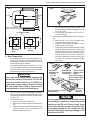
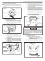
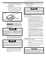
FIG. 4
4"
FIG. 5
4"
7-1/8”
4-1/8”
REAR
OF
UNIT
21-3/8”
Center Line
of Unit
14-1/4" x 14-1/4”
(±1/8”) OPENING
7-1/8”
KEEP THESE AREAS
FREE OF OBSTRUCTIONS
d. If the opening exceeds 14-3/8" x 14-3/8", it will
be necessary to re-size the opening to 14-1/4"
x 14-1/4" (±1/8").
e. If the opening is less than 14-1/8" x 14-1/8", it
must be enlarged.
3. New Opening- (Installation Other Than Vent Opening)
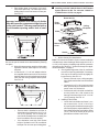
a. Mark a 14-1/4" x 14-1/4" (±1/8") square on the
roof and carefully cut the opening.
b. Using the roof opening as a guide, cut the
matching hole in the ceiling.
c. The opening created must be framed to provide
adequate support and prevent air from being
drawn from the roof cavity. Lumber 3/4" or more
in thickness must be used. Remember to provide an entrance hole for power supplies, furnace wiring and a seven-conductor cable, 18 to
22 AWG is to be used for analog thermostat
connections.
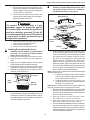
12"
Air Grill Perimeter
2"
1-1/2"
F
r
o
n
t
18-1/2"
17"
1-1/4"
1-3/4"
14-1/4 x 14-1/4
(±1/8")
Opening
14-1/4 x 14-1/4
(±1/8")
Opening
3"
1-1/2"
17"
Standard
Grill
3"
R
e
a
r
2"
20-7/8"
Genesis
C. Roof Preparation
1. Opening Requirements - Before preparing the ceiling opening, the type of system options must be
decided upon. Read all of the following instructions
before beginning the installation.
If a roof vent opening will not be used a 14-1/4" x 141/4" (±1/8") opening must be cut through the roof and
ceiling of the RV. This opening must be located
between the roof reinforcing members.
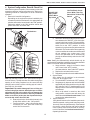
FIG. 6
Do Not Cut
Roof Structure
Or Rafters
3/4" Min.
There may be electrical wiring between the
roof and the ceiling. Disconnect 120 volt AC
power cord and the positive (+) 12 volt DC terminal at the supply battery. Failure to follow
this instruction may create a shock hazard
causing death or severe personal injury.
Good-Rafters
Good LocationSupported By Between Roof
Cross Beams
Rafters
Frame Opening So It
Won't Collapse When
Bolting Down Unit
Leave Access For Power
Supply Wiring
The 14-1/4" x 14-1/4" (±1/8") opening is part of the
return air system of the Air Conditioner and must be
finished in accordance with NFPA Standard 501C
Section 2.7.2.
2. Roof Vent Removal
a. Unscrew and remove the roof vent.
b. Remove all caulking compound around opening.
c. Seal all screw holes and seams where the roof
gasket is located. Use a good grade of all
weather sealant. See FIG. 5.
15" Min. At
Front Of
Opening
CAUTION
It is the responsibility of the installer of this
air conditioner system to ensure structural
integrity of the RV roof. Never create a low
spot on the roof where water will collect. Water standing around the air conditioner may
leak into the interior causing damage to the
product and the RV.
5