1
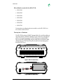
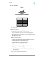
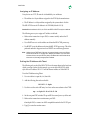
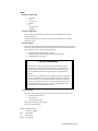
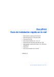
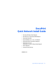
MIL-4711H
Manageable Hub
MICROHUB 10BASET MANAGED HUB WITH MODULAR UPLINK MODEL MIL¥4711H
LINK
RECEIVE
PARTITION
LINK
RECEIVE
PARTITION
1
2
3
4
5
6
7
8
User’s Guide
This guide includes the following information:
“Description of Hardware” on page 2
“Description of the LEDs” on page 3
“Description of Dip Switches” on page 3
“The DB-9 Serial Port” on page 4
“Installation Procedure” on page 4
“Assigning an IP Address” on page 5
“Setting the IP Address with Telnet” on page 5
“Setting the IP Address with RARP” on page 6
“Setting the IP Address with BOOTP” on page 7
“Verifying the IP Address is Set Properly” on page 8
“Legal” on page 9
Doc. Number: 75425 Rev. A
Install Guide
Micro Mo d ules used wit h t he M IL- 4711H:
• MIL-4310M
• MIL-4320M
• MIL-4330M
• MIL-4340M
• MIL-4350M
• MIL-4360M
• MIL-4370M
For instructions on configuring the micro modules, see the MIL-4300M Series
Micro Module Installation Guide..
D es c rip tio n of Hardware
The MIL-4711H is an 8-port, 10BASE-T managed hub with a modular uplink port
supporting 10BASE-T, 10BASE2, 10BASE-FL or AUI connectivity, and an RS-232
port for out-of-band management. The MIL-4711H supports standard MIB-II,
Digi's private MIBs, and hub MIBs using the SNMP protocol with both in-band
management (over TCP/IP and IPX protocols) and out-of-band management
through an RS-232 port.
MICROHUB 10BASET MANAGED HUB WITH MODULAR UPLINK MODEL MIL¥4711H
LINK
RECEIVE
PARTITION
LINK
RECEIVE
PARTITION
1
2
3
4
5
6
7
8
Figure 1. MIL-4711 (Front View)
X
X
MIL-4300M
16VAC
Figure 2.MIL-4711 (Rear View)
Model: MIL-4711H
2
Install Guide
X
FT
RX
LK
CX
X
MIL-4300M
MIL-4310M
16VAC
Figure 3.MIL-4711 (Rear View w/ the MIL-4310 Module)
D es c rip tio n of t he LEDs
On the front panel of the MIL-4711H, there is one LED above each of the eight,
10BASE-T ports. If the port is in use, the LED will change to one of three colors to
indicate the following functions:
• Green indicates link present
• Red indicates that the port is partitioned
• Orange indicates that the port is receiving data
There are four LEDs located between the power plug and the DB-9 serial port on
the rear panel. The following gives the rear panel LEDs' function:
• Green LED in the upper-left corner is the system LED (SYS)
• Green LED in the lower-left corner is the power LED (PWR)
• Yellow LED in the upper-right corner is the network LED (NET)
• Red LED in the lower-right corner is the collision LED (COL)
Note:
The SYS and COL LEDs blink when the unit is operational.
D es c rip tio n of Dip Swit ches
To the right of the DB-9 serial port (on the rear of the hub) are two DIP switches.
The switch to the left and closest to the DB-9 is Switch 2, and the switch to the
right is Switch 1. The following table gives the function of these DIP switches:
Switch 2
Off (Down)
Off (Down)
On (Up)
Model: MIL-4711H
Switch 1
Off (Down)
On (Up)
On (Up)
FUNCTION
Normal Mode (Telnet Disabled)
Normal Mode (Telnet Enabled)
Monitor Mode, SNMP (Agent not Operational)
3
Install Guide
T h e D B -9 S erial Por t
DB-9
1
Figure 4.RS-232C Serial Port Pin Assignments
DB-Male Pin #
1
2
3
4
5
6
7
8
9
Note:
Function
N/C
RXD
TXD
DTR
GND
N/C
DTR
CTR
N/C
N/C=No Connect
In stalla tio n Procedure
Follow these steps to connect the MIL-4711H to your network:
1. Remove the MIL-4700H, power adapter, and cord from its shipping box.
2. Select the appropriate AC voltage (120VAC or 220VAC) on the power adapter.
The voltage in use is visible.
Warning:The factory setting is 120VAC.
3. If you have optional micro modulse, connect their cabling from the media to
the network. Refer to the MIL-4300M Installation Guide.
4. Connect the 10BASE-T UTP cabling to the front ports.
5. Plug the power cord into the 4711H and into an AC outlet.
6. Apply power to the unit. The power LED located on the left rear of the unit
next to the power connector should light up.
Note:
To get the network connectivity, cascade the MIL-4711H to another hub using a swap
cable at the front ports.
The MIL-4711H is now ready for use on the network.
Model: MIL-4711H
4
Install Guide
A ss ig n in g an IP Address
Every device on a TCP/IP network is identified by two addresses:
• The address is a 6-byte address assigned to the 4711H by the manufacturer.
• The IP address is a 4-byte address assigned by the system admin. Set this.
The MIL-4711H stores its IP address in its NVRAM (default: 0.0.0.0).
Caution:When the address is 0.0.0.0, the 4711H uses RARP or BOOTP to acquire an address.
The following are ways to assign an IP address to the hub:
• Make a telnet connection via port 2002, or connect serially and set the IP
address manually.
• Use a RARP server to set the address each time the MIL-4711H powers up.
• Use BOOTP to set the address each time the MIL-4711H powers up. This is the
preferred method in larger networks as BOOTP can work through routers.
Note:
Neither telnet nor RARP work if the server is connected through a router on a different
subnet from the MIL-4711H. To assign an IP address, put the MIL-4711H on the same
subnet as the host, set-up an ARP entry with an IP address that is valid for that subnet,
telnet to the unit, and assign an appropriate IP address.
S e ttin g th e IP Address wit h Telnet
The following only works if the MIL-4711H is on the same subnet as the host from
which you want to telnet. In this example, you are to add a MIL-4711H called
alpha with an IP address 192.185.2.3 and an Ethernet address of 0040c800012B.
To set the IP Address using Telnet:
1. Use a text editor to open the /etc/hosts file.
2. Add the following line and save the file:
192.185.2.3 alpha
3. Use this to set the static ARP entry for a host on the same subnet as the 4711H:
arp -s alpha 00:40:c8:00:01:2B
4. Set the rear panel DIP switches D2 up and D1 down and power cycle the unit.
5. Make a telnet connection to maintenance port 2002:
telnet alpha 2002, or connect an ANSI compatible terminal to the RS-232 port
6. Type [!] to enter the monitor menu.
Model: MIL-4711H
5
Install Guide
7. If prompted with a message like Warning: Entering monitor will lock out
other Ethernet access and force reset, type [Y] to get the command prompt.
8. Type [N] to enter the network protocols menu.
9. Type [T] to enter the TCP/IP menu.
10. Change the settings for the TCP/IP engine options as prompted.
11. Return to the main menu and reboot the MIL-4711H with the [R] command.
Note:
On IBM RS-6000 systems, use the following command instead of the command given in
step 3 to specify that the connection is Ethernet II:
arp -s ether alpha 0:40:c8:0:01:2B
On AT&T Star servers and NCR systems, use this command:
arpbypass set alpha 0x00.0x40.0xc8.0x00.0x01.0x2B
On Windows 95/98 or NT with TCP/IP systems, use this command:
arp -s alpha 00-40-C8-00-01-2B
The MIL-4711H is now configured on the network.
S e ttin g th e IP Address wit h RARP
RARP provides a way for devices on the network to query a server for their IP
address at start-up. This only works if the 4711H is on the same subnet as the host
running the RARP daemon. however, it will RARP if its address is set to 0.0.0.0.
To set the IP Address with RARP:
1. Verify that you have RARP (usually located in the /usr/etc directory).
2. Find the hardware address of the MIL-4711H (on the bottom of the unit).
3. Add the address to the /etc/ethers file, or the NIS master ethers database. For
example, if a device named alpha has an address of 0040C802ABCD, then add:
00:40:c8:02:ab:cd:alpha
4. Add the IP address and the host name to the /etc/hosts file. For example, a
device named alpha with an address 192.185.2.3, add the following line:
192.185.2.3 alpha
Note:
For hosts using NIS and ethers databases, rebuild the databases at this time. Change to
the YP directory and type make at the command prompt. Then continue this procedure:
5. Power on the MIL-4711H.
Model: MIL-4711H
6
Install Guide
6. Verify that the RARP daemon is running:
ps-ax | grep RARP (for BSD UNIX) or
ps-ef | grep RARP (for System V UNIX)
Otherwise, start the RARP daemon by typing:
/usr/etc/rarpd-a or /etc/rarpd-a
If successful, the SYS LED flashes five times per second until the 4711H resolves
its IP address. Then it flashes once per second after address resolution.
Note:
The IP address in this case is stored in RAM. Hence, if the MIL-4711H is powered off, the
address will be lost and when the unit is powered on, the MIL-4711H will RARP again.
S e ttin g th e IP Address wit h BOOTP
BOOTP allows a diskless client machine to discover its own IP address. Unlike
RARP, BOOTP is IP/UPD based and it can pass through routers.
To set the IP Address with BOOTP on a Sun system:
1. Verify that you have BOOTP (usually located in the /usr/etc directory).
2. Use a text editor to open the /etc/hosts file.
3. Add the host name and address, and then save the file. For example, for a
MIL-4711H called alpha with an IP address 192.185.2.3, add this line:
192.185.2.3 alpha
4. Edit BOOTP in the /etc directory containing the hostname of the MIL-4711H,
hardware type, hardware address, and the IP address. Format the entry:
<hostname of MIL-4711H>:ht=1:ha=<hardware address>:ip=<ip address>
For example, an entry named alpha, with a hardware address of 0040c8010203
and an IP address of 199.86.12.183:
alpha:ht=1:ha=0040c8010203:ip=199.86.12.183:
5. Start the BOOTP daemon by typing the command /usr/etc/BOOTPd. The
MIL-4711H will broadcast BOOTP packets and will obtain a response from the
server and will use the IP address specified in /etc/BOOTP file.
To se t th e IP Address wit h BOOTP on a HP/UX s yst em :
1. Login as root on the system and start SAM, the System Administration Tool,
by entering sam at the command line.
Model: MIL-4711H
7
Install Guide
2. Use a text editor to open the /etc/hosts file and add the following line:
192.185.2.3 alpha
3. Use the following menu sequence in sam:
Networking--> Communications--> Device Connectivity-->
Boot Protocol--> Actions--> Add
4. In response to the program prompts, add the following information:
BOOTP Device Name: <specify the hostname of the MIL-4711H>
Internet address: <specify the IP address of the MIL-4711H>
Subnet address: <specify the subnet mask of the MIL-4711H>
Station address (hex): <specify the hardware address of the MIL-4711H>
Boot file name: <specify the full path of this file> (e.g.: /etc/BOOTPtab)
5. Answer the prompt for BOOTP Device Adapter Type by clicking first on
Ethernet and then click on Apply.
6. Exit out of SAM.
7. Start BOOTP.
The MIL-4711H will broadcast BOOTP packets and will obtain a response
from the server using the IP address specified in /etc/ BOOTPtab file.
If the BOOTP process is successful, the SYS LED flashes five times per second
until the MIL-4711H resolves its IP address. It flashes once per second after
address resolution.
Note:
The IP address in this case is stored in RAM. When the MIL-4711H is powered off, the
address will be lost and when the unit is powered on, the MIL-4711H will RARP again.
Verifyin g the IP Address is Set Properly
To see if the 4711H is up and responding on the network, use the ping command:
ping <hostname>
It should respond with a message that the host is alive. For example, if the MIL4711H alpha is responding on the network, the response from ping will be:
alpha is alive
If there is a problem resolving the MIL-4711H name, try using ping with the IP
address for the MIL-4711H:
ping <ip-address>
Model: MIL-4711H
8
L eg al
Regulator y Approvals
•
•
•
•
•
FCC Class A
UL 1950
CSA 22 No. 950
EN60950
CE
– EN55022 Class B
– EN50082-1
Canadian EMI Notice
This Class A digital apparatus meets all the requirements of the Canadian Interference-Causing
Equipment Regulations.
Cet appareil numérique de la classe A respecte toutes les exigences du Règlement sur le matériel
brouilleur du Canada.
European Notice
Products with the CE Marking comply with both the EMC Directive (89/336/EEC) and the Low Voltage
Directive (73/23/EEC) issued by the commission of the European Community. Compliance with these
directives implies conformity to the following European Norms:
•
•
•
EN55022 (CISPR 22) - Radio Frequency Interference
EN50082-1 (IEC801-2, IEC801-3, IEC801-4) - Electromagnetic Immunity
EN60950 (IEC950) - Product Safety
Five-Year Limited Warranty
Digi International warrants to the original consumer or purchaser that each of its
products, and all components thereof, will be free from defects in material and/or
workmanship for a period of five years from the original factory shipment date. Any
warranty hereunder is extended to the original consumer or purchaser and is not
assignable.
Digi makes no express or implied warranties including, but not limited to, any implied
warranty of merchantability or fitness for a particular purpose, except as expressly set
forth in this warranty. In no event shall Digi be liable for incidental or consequential
damages, costs, or expenses arising out of or in connection with the performance of the
product delivered hereunder. Digi will in no case cover damages arising out of the
product being used in a negligent fashion or manner.
To Contact Digi
For prompt response when calling for service information, have the following information ready:
•
•
•
Product serial number and rev.
Date of purchase
Vendor or place of purchase
Reach Digi Technical Support at 408/744-2751
Or E-mail at “[email protected]”
Address: 1299 Orleans Drive
Sunnyvale, CA 94089
Voice:
408/744-2775
Fax:
408/744-2793
E-mail: [email protected]
Doc. Number: 75425 Rev. A