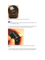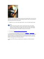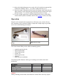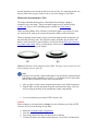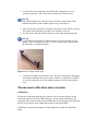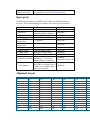
1
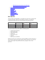
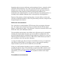
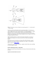
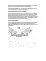
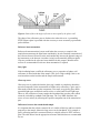
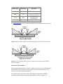
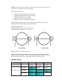
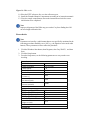
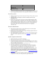
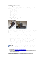
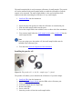
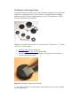
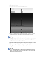
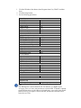
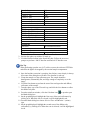
Diffuse Reflectance Accessory (Internal)
Note: This document is also available in PDF format for improved print quality.
PDF files are stored in the "\Manuals" folder on the Help & Videos CD-ROM.
For the Cary 4000, 5000 and 6000i
Click here for Cary 4, 400, 5, 500 and 500i
Part Numbers: Internal DRA 900: 0010080900
Internal DRA 1800: 0010081000
Internal DRA 2500: 0010081100
Installation category I
Pollution degree 2
Safety class 1 (EN 61010-1)
Refer to the Safety section of the online Help for an explanation of the warnings and
cautions used in this document.
Table of Contents
•
•
•
•
•
•
•
Introduction
Theory
Optical design
Specifications
Getting started
o Unpacking
o Installation
o Alignment
o Checking for the specular component
o Error checks
Installing attachments
o Installing the liquid sample holder
o Installing the small sample holder
o Installing the powder cell
o Installing the small sample mount
o Installing the polarizer
o Installing the double aperture attachment
Operation
o Transmission measurements (liquid samples)
o Transmission measurements
o Reflectance measurements
NIR reflectance measurements (Cary 5000 only)
Specular-only reflectance measurements
Measurement calibration and corrections
Maintenance
Standards
Troubleshooting
Spare parts
Alignment targets
Sample mounting kits
References
o
o
•
•
•
•
•
•
•
•
Introduction
The three different internal DRAs are compatible with each of the Cary 4000, 5000
and 6000i instruments. While all of the following variations are available the
configurations indicated by ticks in the table below offer optimal operation.
(Internal DRA 900)
(Internal DRA
1800)
(Internal DRA
2500)
Cary 4000
Cary 5000
Cary 6000i
The Varian internal DRA provides different mounting options:
•
•
•
•
•
•
•
standard sample holder kit;
liquid sample holder;
small sample holder;
powder cell;
small sample mount:
polarizer;
double aperture attachment.
Reflection consists of two components: specular and diffuse. Specular reflectance is
the mirror-like reflection off a sample surface. Diffuse reflectance occurs when the
surface reflects light in many different directions, giving the surface a matt
appearance.
Figure 1: The two components of reflection: specular and diffuse reflection. n
represents the surface normal, an imaginary line at 90° to the sample surface.
Traditionally, the accessory used to measure diffuse reflectance is the integrating
sphere. Applications include characterizing solar materials, color measurement and
characterization, and obtaining reflectance spectra of a painted surface. Integrating
spheres have also proven ideal for measuring the transmission of turbid, translucent or
opaque refractory materials where standard techniques proved inadequate due to loss
of light resulting from the scattering effects of the sample. Samples which distort the
beam of the instrument, such as a lens, can also be studied with the Diffuse
Reflectance accessory.
The Cary 4000, 5000 and 6000i Internal Diffuse Reflectance accessory (DRA)
consists of a 110 mm diameter integrating sphere. The coating is
Polytetrafluoroethylene (PTFE), which exhibits NIR performance that is superior to
traditional coatings(1), whilst maintaining UV-Vis performance. The sphere is easily
installed by the lock down™ mechanism in the sample compartment of the
instrument. The three different versions of the DRA have different detectors that
determine the wavelength range at which measurements can be taken. These are
detailed in the Specifications section.
Reflectance measurement of a sample is made relative to a reference material (either a
PTFE or a BaSO4 plate) or a standard reference material. The reference material is
used to establish a baseline, and when the standard reference material is being used,
the absolute reflectivity of a sample may be calculated from that of the reference. For
further details, refer to the Reflectance measurements section.
The DRA requires the Extended Sample Compartment, part number 00 00100798 00
(Cary 4000, 5000, 6000i and DeepUV).
Theory
Integrating spheres measure reflectance and transmittance factors, commonly called
reflectance and transmittance. The relative spectral reflectance (transmittance) is
defined as the ratio of the flux reflected (transmitted) by the specimen to that of a
standard surface under identical geometrical and spectral conditions. For
transmittance the standard surface is air, and for reflectance the standard surface is a
secondary white standard calibrated relative to the perfectly reflecting diffuser.
Because of the geometry of the integrating sphere, it has the ability to collect most
reflected or transmitted radiation, remove any directional preferences, and present an
integrated signal to the detector.
Reflectance measurements
First, a baseline is recorded with the PTFE reference disk covering the reflectance
port. The sample is then mounted over the port and the reflection off the sample
surface is collected by the sphere. The reflectance is therefore measured relative to the
PTFE disk. This is the 'substitution' method.
The total (diffuse and specular) or the diffuse-only reflectance may be measured by
mounting the sample against the sphere port in two different configurations. The
specular component may be calculated from the difference of these two, or the Cary
Absolute Specular Reflectance Accessory (SRA P/N 00 100438 00) may be used to
give an absolute value of the specular component.
A variety of sample types and sizes may be used with the accessory, in conjunction
with different sample holders. For powders, pastes or other material requiring a
sample container, a powder cell is available for use in the DRA.
If only very small amounts of powder or paste are available, or if measurements
extending beyond the range of 250–2500 nm are required, the DRA cannot be used.
The 'Praying Mantis' accessory (P/N 00 100469 00) is used for these measurements.
Alternatively, you can use the powder cell in conjunction with the small sample
holder.
Transmittance measurements
Figure 2: Collection of scattered light by an integrating sphere. Io = incident light, Is
= scattered light.
In order to perform useful measurements on scattering samples, it is necessary to
collect a high proportion of the scattered radiation. The integrating sphere is a highly
efficient collector of scattered radiation. Because of its design, the Diffuse
Reflectance accessory overcomes many of the problems associated with measuring
turbid or scattering samples, which include sloping baseline, poor signal-to-noise ratio
and high background absorbance.
Whilst the DRA should be used when measuring the transmittance of opaque or
diffusing solid samples, the accessory may also be used when measuring turbid
liquids.
Because the cuvette is located so as to be part of the wall of the sphere, a greater
proportion of the scattered radiation transmitted by the sample is collected by the
sphere, as shown in Figure 2 above.
With the PTFE reference disk in position, a sample is placed in the cuvette, and light
is passed through the sample.
Factors affecting accuracy or precision
Below are the major factors that may affect the accuracy of measurements when using
the DRA.
Aperture area/total surface area ratio
Some of the reflected light escapes through the ports. This has the effect of reducing
the signal to noise ratio, and thus the precision of the measurement.
The Commission Internationale de l' Eclairage (CIE) recommendation is a ratio of
<10%. This figure is only 3% for the Cary internal DRA.
Coating non-uniformity, ageing, or contamination
This accessory has been coated with PTFE via a unique process that ensures both a
uniform coating on the inside of the sphere and the correct powder density. PTFE is
durable, and does not yellow. The reflectivity of the PTFE is above 96% between
200–2500 nm, and greater than 99% between 350–1800 nm. The sphere will maintain
its reflectivity indefinitely if not subjected to smoke or other contaminants. Contact
with plastic materials may also contaminate the coating.
Incorrect sample placement
Theory assumes that the sample placement will coincide with the inside of the sphere
wall. The sample is normally placed at a port on the outside of the sphere wall.
Spacing between the sample and the sphere wall can lead to large errors due to loss of
reflected light.
Figure 3: Some of the wide-angle scatter is lost when there is a space between the
sample and the sphere wall
Sample recess
Theory assumes that the sample is placed coincident with the inside of the sphere
wall, however the sample is placed against the outside of the sphere wall. The
porthole edges have a finite thickness, and some part of the beam reflected at wide
angles may be intercepted by the sphere wall.
Figure 4: Some of the wide-angle reflection is intercepted by the sphere wall
The edges of the reflectance port are feathered to reduce this error. A protruding
PTFE reference plate is provided with the accessory to more accurately represent the
perfect diffuser.
Reference beam attenuation
Reference beam attenuation is most useful when the accessory or sample in the
sample beam attenuates the light beam considerably. In such situations, attenuation of
the reference beam will increase noise and considerably increase the dynamic range of
the instrument, as the detector is not then 'seeing' two dramatically different signals.
Clips are provided at the reference beam window for this purpose. Metallic mesh
screens are recommended if reference beam attenuation is required.
Stray light
If the irradiating beam overfills the reflectance port, a proportion of sphere wall
reflectance is mixed with that of the sample. This gives a high reading if this is not
consistent between the baseline and the sample measurement.
Gloss trap error
Gloss trap error is produced when the gloss trap is unable to completely absorb the
specular component. In the measurement of diffuse-only reflectance, a 'gloss trap' is
often used to absorb the specular component. Gloss traps are typically glossy black
pyramidal light traps, matt black-coated cavities, or razor blade Fresnel light traps.
However, the reflectance of many samples has broadened the specular peaks which
cannot be excluded by standard sized light traps. The Cary DRA eliminates this
source of error entirely by reflecting the specular component out of the transmission
port.
Differences between the standard and sample
It is important that the reference material be of a similar reflectivity and have similar
properties to the sample. Otherwise large errors can be introduced, if for example a
poorly reflecting material is measured relative to a highly reflective PTFE reference
plate. The table below lists the appropriate reference materials that are recommended
for use.
Surface type
Reflectivity
Reference
Matt
High
PTFE reference plate
Matt
Low
Labsphere diffuse
reflectance standards
Glossy
High
Protruding PTFE
reference plate
Glossy
Low
NIST SRM 2021
The Troubleshooting section contains information on the available reference surfaces.
Figure 5: Highly diffuse samples are measured against a flat PTFE reference plate
Figure 6: The protruding PTFE reference plate more accurately emulates highly
specular samples
Inaccuracy in the standard
If the standard material used to calculate a value is not accurate, this will hamper the
determination of the reflectance of the sample. Great care must be taken to keep
reference materials clean and unscratched.
For a detailed discussion on the factors affecting the measurement of diffuse
reflectance and transmittance with integrating spheres, refer to reference (2).
Optical design
Figure 7: The optical design of the DRA
1. The sample beam hits mirror M1 and is then reflected to M2.
2. The beam travels through the lens and is focused into the transmission port,
and onto the reflectance port.
3. The reflected beam is diffused throughout the sphere before being measured
by the detector.
4. The reference beam enters the sphere directly through the reference port and is
dispersed.
5. The removable end cap has two positions:
•
•
In the 'D' position, the angle of the beam from the normal to the sample plane
is approximately 0 degrees. Any specular component of the reflection is
reflected back through the transmission port and is deflected by the angled
lens, preventing re-entry into the sphere.
With the cap in the 'S' position, the angle of incidence is 3° 20 min. The
specular component will hit the sphere wall and be diffused within the sphere.
The total reflectance will then be measured.
Figure 8: Position 'D' measures diffuse reflectance only. Position 'S' measures total
reflectance by including the specular component.
The sphere has five ports:
1.
2.
3.
4.
5.
Sample beam transmission port (19 x 17 mm)
Sample measurement port (16 mm diameter)
Reference beam port (11 x 13 mm)
NIR detector port (11 mm diameter)
PMT port (oval, 30 mm long x 14 mm wide)
The PMT, PbS and InGaAs detectors are mounted on top of the sphere, which is
alternately illuminated by sample and reference beams.
Beam image dimensions:
transmission port 11.04 mm (h) x 13.44 mm (w)
reflectance port 12.50 mm (h) x 7.11 mm (w)
Figure 9: The beam through the accessory
The reference disks supplied with the accessory are 6 mm deep and the powder is
added to a density of 1 g/cm3. This is the optimum thickness and density of PTFE, to
ensure maximum reflectivity(3) and therefore the best absolute accuracy.
Specifications
+ 85 volts DC (Cary
4000/5000/6000i)
Cary 4000
Wavelength range
Cary 5000
Cary 6000i
DRA 900
DRA 1800
DRA 2500
200 nm to
900 nm *
200 nm to
900 nm *
200 nm to
900 nm *
200 nm to
200 nm to
900 nm
900 nm
200 nm to 1800 200 nm to
nm *
2500 nm *
200 nm to
200 nm to 1800
nm
1800 nm *
Detectors
UV/VIS
NIR
Sphere diameter
Internal coating
Coating density
Coating thickness
Sample plane normal deviation
Port area/total surface area ratio
reflectance port size
Minimum sample size
Maximum sample size
Power input
Size packed
Size unpacked
Weight packed
Weight unpacked
R928 PMT
R928 PMT
TE# cooled
InGaAs
R928 PMT
TE# cooled PbS
110 mm
Polytetrafluoroethylene (PTFE)
1 g/cm3
4 mm
0° (diffuse reflectance only)
3° 20 min (total reflection)
(CIE recommendation: <10°)
3%
(CIE recommendation: <10%)
16 mm diameter
Approx 8 mm (w) x 12 mm (h)
100 mm (w) x 200 mm (h)
Sample compartment DRA connector
15-pin D-range connector with two high voltage
pins: -1000 volts DC,
180 mm x 390 mm x 270 mm (W x L x H)
140 mm x 340 mm x 200 mm (W x L x H)
8 kg
5 kg
* The blue colouring indicates the recommended configurations of instruments and
DRAs. While other configurations will still work the performance will not be optimal.
#
Thermoelectrically cooled
The accessory is suitable for indoor use only. Suitable for Installation Category I and
Pollution Degree 2. Environmental conditions are the same as for the Cary
spectrophotometer.
Getting started
This section describes how to unpack, install and align your Diffuse Reflectance
accessory.
Figure 10. The internal DRA. Note the clips on the left hand side of the accessory.
These are for attaching metal screens during reference beam attenuation.
Caution
This accessory includes mirrors, lenses and other fragile parts.
Treat the packaging and accessory with care. Do not jar the accessory. Avoid finger
contact with mirrors and lenses. Do not attempt to clean or repair damaged surfaces.
Caution
If the equipment is not used in a manner not specified by the manufacturer, the
protection provided by the equipment may be imparied.
Unpacking
Open the shipping case and the enclosed packages with care.
Included in the package are the following:
Item
Description
Part number
1 x Mirror
Alignment target
M4 3mm hexagonal ball driver
for horizontal mirror alignment
20 100625 00
1 x Ball driver
1 x 5.5 mm AF nut
driver
1 x Polarizer mount
1 x Large PTFE
reference plate
1 x Protruding PTFE
reference plate
1 x Alignment target
For vertical mirror alignment
72 100208 00
72 100243 00
(already installed)
1 ¾” diameter
04 101439 00
04 101988 00
Translucent polyester film
24 180044 00
Inspect all parts for damage in transit. Any damage should be reported immediately.
Please refer to the accessory by model and serial number.
If you have also ordered any of the specialized sample mount options you must also
inspect these kits. The Standard Sample Holder kit is included as standard with each
DRA.
The Standard Sample Holder kit includes the following:
Item
Description
1 x Sample clamp
1 x Paddle clamp
1 x Small clamp
Spring clip sample clamp
01 103359 00
White plastic sample clamp
01 106122 00
Black plastic sample clamp
08 180146 00
Permits mounting of 1” and 2”
ledges, paddles and clamps in %T 08 101699 00
and %R modes
Round poles with one flat side (1
15 180540 00
already installed)
6 x Round poles
2 x Poles
Part number
1 Sample mount ledge
Permits mounting of 1” and 2”
samples in %T and %R modes
08 101697 00
The Standard Sample Holder Kit will accommodate mounting of reflectance
standards, specifically:
Item
Description
Protruding PTFE
reference plate
Large PTFE reference
plate
2” Reflectance standards
1” color standards
1 ¾” diameter
Reflectance standards (Spectralon) 2”, for use with Diffuse
reflectance accessories
Calibrated diffuse color standards set for DRA. Set includes
four 1” D diffuse color standards. Red, green, blue and
yellow
Click here for details of what is included in each of the other sample mounting kits.
Installation
You will need:
•
•
•
A flat blade screw-driver (is included in the instrument tool kit)
A 3 mm hexagonal ball driver
The Extended Sample Compartment
1. Turn off the spectrophotometer and remove any cell holders or other
accessories from the sample compartment. The PC can be left on.
2. Close the sample compartment, turn the spectrophotometer on and allow it to
initialize.
3. Open the accessory case and remove the metal clamp and alignment target.
4. Use the hex ball driver to remove the shipping hex screw from the the end cap
of the sphere.
5. Remove the accessory cable from the white cable clamp.
6. Remove the cover over the mirrors by loosening the two screws on top of the
cover and place to one side.
Figure 11: The Cary 4000, 5000 and 6000i Internal Diffuse Reflectance accessory
with the optics cover removed. The large reference plate is clamped over the
reflectance port at the centre of the sphere cap.
Warning This accessory contains electrical circuits, devices, and components
operating at dangerous voltages. Contact with these circuits, devices and
components can cause death, serious injury or painful electrical shock.
To prevent electrical shock operators and other unauthorized personnel
must never remove the cover. This must be opened only by Variantrained, Varian-qualified or Varian-approved service engineers.
7. Position the accessory so that the two rear lock-down feet are situated at the
back of the sample compartment and gently lower the accessory so that the
front pin on the base plate fits into the post clamp on the sample compartment
floor. Ensure that the base of the accessory is parallel to the sample
compartment floor.
8. Slide the lever at the front of the sample compartment to the left, to lock the
base plate into position.
Caution
Do not plug the DRA into the spectrophotometer when the latter is turned on, or
electronic damage may occur.
9. Take the clamp post from under the foam in the wooden shipping case and
fasten it in the hole in the accessory cap. Place the sample clamp on the clamp
post.
Alignment
Warning To avoid eye damage use care when looking into the various ports
during the alignment process. Do not look into the light beams.
1. Click the Windows Start button, then Programs, then Cary WinUV, and then
Align.
2. Click the Cary tab.
3. Set the following parameters:
Double
beam:
Normal
Y mode:
%R
Ave time:
0.1
SBW:
2
Slit
height:
reduced
4. Select the Zero order check box and click OK.
Caution
The DRA should not be plugged in and operated with the instrument set to 0 nm. If it
is, the detectors will be flooded with white light, which will decrease the sensitivity of
the accessory and increase noise. If this should happen, place the DRA in a dark place
for 24 hours to allow it to recover.
5. Remove the front cap from the accessory and observe the diffuser at the
reference port. The image should be centered on the diffuser.
If it is not:
•
•
6.
Check that that DRA is correctly locked down onto the
instrument sample compartment floor.
If the DRA is correctly installed, and misalignment persists,
contact your local Varian service representative.
Replace the sphere cap with the 'S' mark upwards.
7. Tape a card over the diffuser on the reference port to exclude light. Make sure
you do not contaminate the surface of the diffuser.
8. Check the adjustment of the Beam on to mirror M2. If necessary adjust the
horizontal alignment of the beam by loosening the screws on either side of
mirror M1 and rotating it slightly.
9. Fasten the screws.
10. Adjust the vertical alignment of the beam on mirror M2 by adjusting the
hexagonal screw at the front of mirror M1.
11. Check that the light is not clipping the lens, the transmission port to the sphere
(at the back of the sphere), or the reflectance port on the sphere (at the front of
the sphere).
12. If necessary, adjust M2 in the same way as M1.
Hot Tip
You will have to remove the accessory from the sample compartment to adjust
the vertical position of the beam with the hexagonal screw at the back of M2.
Checking for the specular component
1. Place the accessory cap in position with the 'D' mark upwards.
2. Clamp the mirror over the reflectance port. The reflective surface of the mirror
should face the reflectance port.
3. The beam reflected from the lens should strike the back of the sphere housing
approximately 10 mm from the edge of the transmission port.
4. Adjust the beam by loosening the screws on either side of the lens and then
rotating the lens to move the beam position.
Figure 12: Simplified beam diagram of the accessory with the sphere cap in the 'D'
position. The specular component is reflected back out of the sphere onto the lens.
The reflection from the lens should be about 10 mm from the transmission port.
5. Re-tighten the screws and re-check the alignment, to see if any lens
adjustment is necessary.
6. Position the sphere cap so that the 'S' mark is facing up. If any part of the
reflected beam exits the transmission port, repeat the alignment and specular
component checks.
Hot Tip
Place the alignment target at the edge of the transmission port (without
blocking the beam from the lens) and rock the mirror over the reflectance port
to identify the reflected beam. When the mirror is placed over the reflectance
port, no part of the beam should be observed exiting the transmission port.
Figure 13: Simplified beam diagram of the accessory with the sphere cap in the 'S'
position
7. Carefully remove the m ask from the diffuser (see step 7). Turn off the
instrument and remove the DRA from the sample compartment.
8. Replace the optics cover on the DRA.
9. With the spectrophotometer turned off, place the DRA in the sample
compartment and plug it into the corresponding socket at the top of the sample
compartment.
Caution
The spectrophotometer must be turned off before plugging in the DRA, or serious
damage may result.
Figure 14: DRA socket
10. Place the PTFE reference disc over the reflectance port.
11. Install the Extended Sample Compartment according to its instruction manual.
12. Close the sample compartment, turn on the instrument and wait for correct
initialization to be completed.
Note
Improper alignment of the DRA may prevent the Cary from finding the 656.1
nm wavelength calibration line.
Error checks
Note
Parameters activated by a radio button that are not specifically mentioned in the
following procedure should be set to 'Off' (e.g., the Signal-to-noise mode radio
button). These parameters will not affect the procedure.
1. Click the Windows Start button, then Programs, then Cary WinUV, and then
Scan.
2. Click the Setup button.
3. From the Setup menu, set the following parameters to carry out the error
checking.
Cary tab
X mode: Mode
X mode: Start/Stop
Y mode: Mode
Y mode: Y min
Y mode: Y max
Scan controls:
Ave time (s)
Scan controls:
Data interval (nm)
Scan controls:
Scan rate (nm/min)
Options tab
SBW/Energy: Fixed SBW
SBW/Energy: SBW (nm)
SBW/Energy: Beam mode
SBW/Energy: Slit height
Source: Lamps
Source: Source
changeover (nm)
Baseline tab
Nanometers
User-set range
%R
-5.00
110.00
1.000
0.500
30.000
ON
2.00
Double
Reduced
UV-Vis
350.0
Correction
None
Autostore tab
File Storage: Storage
OFF
4. Click the 'Goto' button to open the 'Goto wavelength' dialog box. Enter '500' in
the wavelength field and click OK. The instrument will then drive to 500 nm.
Zero %R error check
1. With the transmission ports uncovered, place the large reference plate over the
reflectance port.
2. From the main 'Scan' dialog box, click the Zero button and wait for the
instrument to zero.
3. Remove the reference plate so the beam is going straight through the sphere
into the Extended Sample Compartment. Close the sample compartment, the
reading should not be greater than 0.5%R. If it is then check the alignment of
the beam through the sphere (adjust M2 as necessary), check that the lens is
clean and free from dust, and ensure that the beam is not clipping the
reflectance port.
Electronic calibration check
1. Place the large reference plate over the reflectance port, close the sample
compartment and then zero the instrument
2. Block the beam with a blanking plate (a large solid object) placed in front of
the transmission port of the sphere.
3. The reading should be less than 0.5%R. If it is not, use the Calibration menu
item in the Validate application. Refer to the Calibration section for further
details.
Specular component exclusion check
1. Position the sphere cap so the 'D' is facing up.
2. Place the large reference plate over the reflectance port.
3. Click the Goto button to open the Goto wavelength dialog box. Enter '500' in
the Wavelength field and click OK. The instrument will then drive to 500 nm.
Close the sample compartment lid.
4. Click the Zero button and wait for the instrument to zero.
5. Place the supplied mirror over the reflectance port, and close the sample
compartment. Note the reading. If the reading is greater than 1.5%R, then
either the specularly reflected beam is not exiting the sphere at the
transmission port, dirt on the lens is scattering the beam and creating a 'halo'
effect on the reflectance port, or the sample mirror does not have a good
specular surface. If the reading is greater than 1.5%R, you should repeat the
check for the specular component as detailed in the Checking for the specular
component section.
6. Rotate the sphere cap 180° so that the 'S' mark is facing up. When the sample
compartment is closed, the reading should be approximately 90%.
Installing attachments
Attachments can be installed into the DRA to increase its flexibility and versatility.
The following are optional attachments:
•
•
•
•
•
•
Liquid sample holder
Small sample holder;
Powder cell
Small sample mount
Polarizer/Depolarizer
Double Aperture
Installing the liquid sample holder
Figure 17. The liquid cell holder. "A" the flat side that must sit against the DRA, "B"
the raiser screw and "C" the screw for securing the attachment to the posts on the
DRA.
1. Screw the posts into position at the transmission port of the sphere.
2. Slide the liquid sample holder onto the posts. The flat side must sit against the
DRA.
3. Check the alignment of the cell holder using the target supplied. Ensure that
the beam is not clipping the edge of the sample holder and is centered on the
sample.
Hot Tip
To assist in preventing the beam from being clipped by the edge of any of the
attachments a SBW of 2 nm is recommended.
4. If necessary recheck the alignment of the DRA.
5. Load a cuvette into the sample holder so that transmission measurements of a
liquid sample can be taken.
Using the liquid sample holder to perform transmission measurements
You must first install the liquid sample holder.
1. Place the protruding reference plate in position in the reflectance port, and
position the cuvette at the transmission port.
2. Set the instrument as detailed in the transmission measurements section.
Note
Parameters activated by a radio button that are not specifically mentioned in the
following procedure should be set to 'Off' (e.g., the Signal-to-noise mode radio
button). These parameters will not affect the procedure.
3. Fill the cuvette with solvent. If necessary, run a baseline as follows:
4. Click the Start button, then Programs, then Cary WinUV then click on Scan.
5. Click the Baseline button. Follow the on-screen prompts to perform a baseline
scan.
Hot Tip
When performing transmission measurements, block the sample beam in the
transmission position with a black masking.
6. Once the baseline correction is complete, the Ordinate status display in the top
left corner of the dialog box will show 'Zero baseline' in red text.
7. Fill the cuvette with the sample and place cuvette in the holder in the same
orientation that was used to collect the baseline.
8. Click the Start button to perform the scan. The Save As dialog box will appear,
allowing the method to be saved as either a data file or a batch file. If the file
is saved as a batch file, all of the method parameters will be stored with the
scan.
Installing the small sample holder
Figure 18. The small sample holder. A = where either the small sample mount or
powder cell are mounted. B = screws for securing the small sample holder to the
DRA. C = screw for holding the small sample mount or powder cell into position. D =
groove for the correct positioning of the powder cell and small spot mount.
The small sample holder is used to measure reflectance of small samples. The powder
cell can be mounted in the small sample holder to enable the reflectance of powder
samples to be measured. The small sample holder is also used to hold the small
sample mount when measuring the reflectance of very small samples.
1. Install the DRA into the instrument.
2. Screw the posts into position at either the reflectance or transmission port.
3. Slide the small sample holder onto the posts.
4. Secure the sample holder onto with the screws at either side of the attachment.
5. You can now install either the small sample mount or the powder cell into the
small sample holder.
Note
If you are going to use the powder cell, the small sample holder must be
installed at the reflectance port.
6. You must now check the alignment of the attachment.
Installing the powder cell
Figure 19. The powder cell. A = lid, B = sample cup, C = funnel.
The powder cell enables you to determine the reflectance of a powder sample.
1.
2.
3.
4.
5.
6.
7.
Install the DRA into the instrument.
Install the Small Sample Holder onto the DRA at the reflectance port.
Fit the funnel onto the sample cup.
Load your sample into the sample cup.
Remove the funnel.
Screw on the lid.
Insert the powder cell into the small sample holder.
Figure 20. Insert the powder cell into the small sample holder.
8. Tighten the screw on the small sample holder to secure the powder cell.
Figure 21. The powder cell fitted into the small sample holder, note that the textured
edge of the powder cell sits flush with the edge of the small sample holder. The screw
to the right of the powder cell is used to secure the powder cell.
8. You must now check the alignment of the attachment.
9. You can use the powder cell to perform reflectance measurements. However
follow this procedure to collect a baseline.
a)
Place a PTFE standard into the powder cell.
b) Click the Zero/Baseline button in the Scan application and collect a 100% T
baseline.
c) Remove the powder cell (containing the PTFE reference), leaving the reflectance
port open.
d) Collect a 0% T baseline. When the 0% baseline is completed the ordinate status
display in the top left corner of the Scan application will show "Zero baseline" in red
text.
Installing the small sample mount
The small sample mount enables you to take reflectance readings of very small solid
samples, for example gemstones. The kit features five different mounts and three
different apertures. The sizes of the apertures are 1mm, 3mm and 5mm. A PTFE
reflectance standard is also included.
Figure 21. The Small Sample mount. "A" sample mounts, "B" apertures, "C" sample
cup and "D" PTFE standard.
1. Install the DRA into the instrument.
2. Install the Small Sample Holder onto the DRA.
3. Place the sample onto the sample mount, you may need to use tweezers to
correctly position the sample.
Figure 22. Placing the sample onto the mask.
4. Place the mount (the size mount used is determined by the size of your sample)
onto the sample cup.
Figrue 23. The mask and sample are placed on the sample cup.
Note
The sample mounts have V-shaped cutouts that enable small samples to assist
in the mounting of samples.
5. Fit the aperture (the aperture size used is determined by the size of your sample)
onto the sample cup, lining up the marking on the lid and the sample cup.
Figure 24. Align the markings on the sample cup and the lid before fitting them
together.
6. The small sample mount is loaded into the small sample holder using the grooves
on each to correctly position the small sample mount into the small sample holder.
Figure 24. The small sample mount fits into the small sample holder. Note that in this
picture the small sample holder and small sample mount are in the correct position for
performing transmission measurements.
7. Tighten the screw on the small sample holder to secure the small sample mount.
Note
Ensure that the small sample mount is sitting forward in the small sample
holder, so that the thumb screw does not prevent the lid of the small sample
mount from sitting up against the DRA. The white lines on the small sample
holder and the powder cell should be lined up with each other.
8.
You must now check the alignment of the attachment.
9. You can use the small sample mount to perform reflectance or transmission
measurements. But use the following procedure to collect the baseline. The following
procedure applies to collecting a baseline for reflectance measurements. If you are
going to be performing a transmission measurement, follow the same procedure but
position the sample cup at the transmission port.
a) Place the PTFE small spot standard into the sample cup. (%R measurements
only).
Figure 25. The PTFE standard fits into the sample cup.
b)
Fit the aperture onto the sample cup.
c)
Place the sample cup over the reflectance or transmission port.
Note
It is recommended that you use the same aperture size to run the baseline as the
one you are going to use for the sample.
d) Click the Zero/Baseline button in the Scan application to collect the 100% T
baseline.
e) If you are performing a reflectance measurement, remove the PTFE standard
from the sample cup and replace the sample cup at the reflectance port with the
aperture attached. If you are performing a transmission measurement, block the
transmission port with a blocking plate.
f)
Click the Zero/Baseline button to collect the 0% T baseline.
g) Once the baseline is complete the ordinate status reading will display 'Zero
Baseline' in red text.
Installing the polarizer
Figure 26. The polarizer installed on the polarizer mount.
You can install the Polarizer/Depolarizer into the DRA to control the plane
polarization of the light beam in a spectrophotometer. For example: if the sample
being measured is sensitive to plane polarized light e.g. liquid crystals, the
transmission of the sample will change as the plane of polarization changes. It is thus
important to control the plane of polarization of the incident beam.
To install the polarizer/depolarizer:
1. Install the DRA into the instrument
2. Remove the optics cover.
3. Slide the Polarizer/Depolarizer onto the polarizer mount. The dial should face
away from the optical area.
4. Tighten the screw to hold the polarizer in place.
5. If necessary re-align the DRA.
You must now check the alignment of the attachment.
Installing the double aperture attachment
This attachment is used in conjunction with the Validate application to check that the
detector in the DRA is performing correctly. The advantage of using the Double
Aperture attachment to determine photometric accuracy is that there is no limitation
on temperature, wavelength or SBW. Refer to the online Help for instructions on how
to use a double aperture attachment. Click here for the theory behind the use of a
double aperture accessory.
Note
The default tolerance values n the Validate application are applicable to the
instrument only. An internal or external DRA accessory should not be expected
to perform to the same level of photometric accuracy.
Figure 27. The Double Aperture attachment. A indicates the locating pin at the
bottom of the attachment.
1. Turn on the instrument and allow it to warm up for at least two hours.
2. Remove the optics cover.
3. Mount the double aperture base onto the polarizer mount.
Figure 28. Install the double aperture base onto the polarizer mount.
4. Install the DRA into the instrument.
5. You must now align the attachment as follows.
6. Place the mask onto the double aperture base so that both apertures are open.
Figure 29. The mask fits onto the double aperture base. This figure shows only one
aperture is open.
7. Click the Windows Start button, then Programs, then Cary WinUV, and then
Align.
8. Set the SBW to 2.00.
9. Close the sample compartment lid.
10. Tick the Zero Order check box, click the Apply button to drive the instrument
to zero.
11. Open the sample compartment lid and adjust the height adjustment screw on
the side of the polarizer mount until the image is centred over the apertures.
Hot tip
Holding a piece of white paper in front of the apertures will made the beam
image easier to see. You can use the aperture mask to draw the apertures on the
paper before mounting the mask.
Figure 30. The image should be centred over the apertures.
12. Close the sample compartment lid and go to the wavelength that you are going
to use for the measurement. Take note of the % transmission reading.
13. Open the sample compartment lid and rotate the aperture mask so that only the
lower aperture is open.
14. Adjust the height adjustment screw on the side of the polarizer mount until the
transmission reading is half (+/- 1%) of the reading noted in step 12.
15. Open the sample compartment lid and rotate the aperture mask so that only the
upper aperture is open. Repeat the measurement until the reading for the upper
aperture is half (+/- 1%) of the reading when both apertures are open.
16. Use the Validate application to check the photometric accuracy of the DRA
with the double aperture attachment. Refer to the Validate section of the help.
Operation
Samples can be mounted at the transmission or reflectance ports. At the reference
port, attenuators may be mounted. Paddles, clamps and a sample ledge are provided
you to assist with mounting your samples.
Figure 31. Front, the Paddle; rear, the
Figure 32. The Ledge
Clamp
The Varian internal DRA provides different mounting options:
•
•
•
•
•
•
•
standard sample holder kit;
liquid sample holder;
small sample holder;
powder cell;
small sample mount;
polarizer;
double aperture attachment
The following table illustrates which type of readings can be taken with which
attachments.
Attachment
Standard
Liquid sample holder
Small sample mount
Powder cell
%T
%R
Caution
When performing measurements and calibrations with the DRA some steps require
that the instrument to be turned on and off at various times. It is important to take care
that you follow these steps as failure to do so can cause damage to your DRA.
Reflectance measurements (%R)
The sample should be homogeneous, substantially flat, and large enough to
completely cover the image. Finely powdered samples may be studied using a
powder cell. There is also a mounting option available for small samples.
When measuring diffuse only reflectance, position the sphere cap with the 'D' mark
up. Position the 'S' mark up to measure the specular+diffuse (total) reflectance.
When performing measurements on glossy materials (high specular component), use
the protruding reference plate. The reference surface protrudes into the sphere and
behaves more nearly like a perfect diffuser. As discussed in the Differences between
the standard and sample section, you should use reference materials with similar
reflectivity and properties to the sample.
Figure 15: Reference disks supplied with the DRA. The large reference plate (a), and
the protruding reference plate (b).
Note
Parameters activated by a radio button that are not specifically mentioned in the
following procedure should be set to 'Off' (e.g., the Signal-to-noise mode radio
button). These parameters will not affect the procedure.
1. After you have carried out the Alignment procedures, turn off the instrument.
2. Plug the DRA into the instrument using the communications plug, it fits into
the green plug at the back of the instrument's sample compartment.
3. Cover the reflectance port with a PTFE reference disc.
Caution
Before turning on your instrument you must cover the reflectance port with a PTFE
reference disc to prevent damage to your DRA.
4.
5.
6.
7.
Install the extended sample compartment.
Close the sample compartment lid.
Turn on the instrument, allow the instrument to initialize.
Click the Windows Start button, then Programs, Cary WinUV and then Scan.
8. Click the Setup button.
9. From the Setup menu, set the following parameters:
Cary tab
X mode: Mode
Nanometers
X mode: Start
700
X mode: Stop
400
Y mode: Mode
%R
Y mode: Y min
-5.00
Y mode: Y max
110.00
Scan controls: Ave time (s)
0.100
Scan controls: Data interval (nm) 1.000
Scan controls: Scan rate (nm/min) 600.00
Options tab
SBW/Energy: Fixed SBW
SBW/Energy: SBW (nm)
SBW/Energy: Beam mode
SBW/Energy: Slit height
Source: Lamps
Source: Source changeover (nm)
ON
2.00
Double
Reduced
UV-Vis
350.0
Baseline tab
Correction
Zero/baseline correction
Autostore tab
File Storage: Storage
Storage on (Prompt at start)
10. Select the 'Baseline' button from the Scan dialog box. Follow the on-screen
prompts to perform a 100%T baseline scan and a 0%T baseline scan.
Hot Tip
When collecting the 0%T baseline scan do not block the beam, instead remove
the PTFE reference disk from the reflectance port and allow the light to be
trapped by the Extended sample compartment.
11. Once the baseline correction is complete, the Ordinate status display in the top
left corner of the dialog box will show 'Zero baseline' in red text.
12. Clamp the sample over the reflectance port. The sample should be
homogeneous, substantially flat, and large enough to completely cover the
image.
Hot Tip
Use the sample mount ledge for added control over the positioning of your
sample. To use the ledge (see figure 16 ) slide it onto the posts fitted at either
the reflectance or transmission ports.
Figure 16. The sample mount ledge.
13. Click the Start button. The Save As dialog box will appear, allowing the
method to be saved as either a data file or a batch file. If the file is saved as a
batch file, all of the method parameters will be stored with the scan.
This procedure will measure the % reflectance relative to the PTFE reference disk.
Note
To determine the absolute diffuse reflectance of a sample, you need to purchase
an NBS standard and calibrate your PTFE disks. The NBS standards SRM
2021 (a black porcelain enamel tile) or SRM 2019c (a white ceramic tile) are
suitable for this purpose.
To determine position and size of the image
To determine the position and size of the image so that samples can be mounted
correctly, follow this procedure:
Note
Initialize the Cary instrument before placing the DRA into the sample
compartment. After initialization, place the DRA into the compartment.
Do not turn the accessory on (i.e., do not plug the DRA into the instrument).
1. Click the Goto button in the Scan application.
2. Select the Zero order check box and click OK. The spectrophotometer will
drive to 0 nm and select the Vis lamp.
3. Place a piece of white paper in front of the sample clamp. The image size
should now be visible.
NIR reflectance measurements (Cary 5000 and 6000i)
Note
Parameters activated by a radio button that are not specifically mentioned in the
following procedure should be set to 'Off' (e.g. the Signal-to-noise mode radio
button). These parameters will not affect the procedure.
Follow steps 1 to 6 of the transmission measurements procedure then:
1. Click the Windows Start button, then Programs then Cary WinUV and then
Scan.
2. Click the Setup button.
3. Set the following parameters:
Cary tab
X mode: Mode
X mode: Start
X mode: Stop
Y mode: Mode
Y mode: Y min
Y mode: Y max
Show status display
Nanometers
1800
300
%R
-5.00
110.00
ON
Options tab
SBW/Energy: Beam mode
Double
SBW/Energy: Slit height
Reduced
Source/Detector: Lamps
UV-Vis
Source: Source changeover (nm) 350.0
Source: Detector changeover (nm)800.0
Independent tab
Independent control
Measurement mode
UV-Vis controls
Ave time (s)
Data interval (nm)
Scan rate (nm/min)
SBW (nm)
NIR controls
Ave time (s)
Data interval (nm)
Scan rate (nm/min)
Energy level
ON
Auto
0.1
1.000
600.00
2.00
1.000
2.000
120.00
3.00
Baseline tab
Correction
Zero correction
Autostore tab
File Storage: Storage
Storage on (prompt at start)
Note
The NIR detector is noisier than the UV-Vis detector, so a higher Signal
Averaging Time (Ave time) may need to be set in the NIR. To obtain a constant
signal-to-noise ratio over the entire wavelength range, set a value in the Signalto-noise field. If you require a faster scan rate, increase the Data interval or
lower the Ave Time.
4. Click the Goto button to open the 'Goto wavelength' dialog box. Enter '801' in
the wavelength field and click OK. The instrument will then drive to 801 nm.
Note
Note the SBW reading in the Status Display dialog box.
5. The SBW reading needs to be at approximately 18. This can be adjusted by
changing the NIR Energy level in the Setup page, under the Independent tab. If
the reading is greater than 18, raise the value of the Energy level field. If the
SBW is under 18, lower the energy level. Once the Energy level has been
adjusted, you will need to click OK in order to note the change to the SBW
reading. Then click the Goto button and again drive the instrument to 801 nm
by entering '801' in the wavelength field and pressing OK. This procedure may
need to be repeated in order to reach the required setting. Please note that each
time you adjust the Energy level reading, you must also drive the instrument to
801 nm.
6. Click the Baseline button in the Scan dialog box. Follow the on-screen
prompts to perform a 100%T baseline scan and a 0%T baseline scan.
Hot Tip
When collecting the 0%T baseline scan do not block the beam, instead remove
the PTFE reference disk from the reflectance port and allow the light to be
trapped by the Extended sample compartment.
7. Once the baseline correction is complete, the Ordinate status display in the top
left corner of the dialog box will show 'Zero baseline' in red text.
8. Clamp the sample over the reflectance port. The sample should be
homogeneous, substantially flat, and large enough to completely cover the
image.
9. Click the Start button. The Save As dialog box will appear, allowing the
method to be saved as either a data file or a batch file. If the file is saved as a
batch file, all of the method parameters will be stored with the scan.
Specular-only reflectance measurements
Note
Parameters activated by a radio button that are not specifically mentioned in the
following procedure should be set to 'Off' (e.g., the Signal-to-noise mode radio
button). These parameters will not affect the procedure.
Follow steps 1 to 6 of the transmission measurements procedure then:
1. From the Setup menu, set the following parameters:
Cary tab
X mode: Mode
X mode: Start
Nanometers
800
X mode: Stop
300
Y mode: Mode
%R
Y mode: Y min
-5.00
Y mode: Y max
110.00
Scan controls: Ave time (s)
0.100
Scan controls: Data interval (nm) 1.000
Scan controls: Scan rate (nm/min) 600.00
Options tab
SBW/Energy: Fixed SBW
SBW/Energy: SBW (nm)
SBW/Energy: Beam mode
SBW/Energy: Slit height
Source: Lamps
Source: Source changeover (nm)
ON
2.00
Double
Reduced
UV-Vis
350.0
Baseline tab
Correction
Zero baseline/correction
Autostore tab
File Storage: Storage
Storage on (prompt at start)
2. Position the sphere cap with the 'S' mark up.
3. Click the Baseline button in the Scan dialog box. Follow the on-screen
prompts to perform a 100%T baseline scan and a 0%T baseline scan.
Hot Tip
When performing specular zero (%T) collect, remove the reference PTFE disc
and allow the light to be trapped by the external sample compartment.
4. Once the baseline correction is complete, the Ordinate status display in the top
left corner of the dialog box will show 'Zero baseline' in red text.
5. Clamp the sample over the reflectance port. The sample should be
homogeneous, substantially flat, and large enough to completely cover the
image.
6. Click the Start button to perform the scan of the total (specular and diffuse)
reflectance of the sample.
7. Turn the sphere cap so the 'D' mark is up, and click the Start button to collect
the diffuse-only data.
8. From the main Scan window, click the Calculator icon
to open the open
the Maths dialog box.
9. On the graph displayed, highlight the first scan (of the total reflectance) by
clicking on it. When the scan is selected, it will be highlighted in red.
10. From the Maths dialog box choose Selected Trace and then the '-' (minus)
sign.
11. On the graph displayed, highlight the second scan (of the diffuse-only
reflectance), by clicking on it. When the scan is selected, it will be highlighted
in red.
12. From the Maths dialog box choose Selected Trace and then the '=' (equals)
sign.
13. The results of this specular data equation will be displayed in a new graph.
Transmission measurements (%T)
Note
Parameters activated by a radio button that are not specifically mentioned in the
following procedure should be set to 'Off' (e.g., the Signal-to-noise mode radio
button). These parameters will not affect the procedure.
1. Place the accessory cap in the 'S' position, and place the protruding reference
plate in position over the reflectance port. Use the metal clamp to hold the
reference cap in position.
2. Set the following parameters:
Cary tab
X mode: Mode
Nanometers
X mode: Start
700
X mode: Stop
400
Y mode: Mode
%T
Y mode: Y min
-5.00
Y mode: Y max
110.00
Scan controls: Ave time (s)
0.100
Scan controls: Data interval (nm) 1.000
Scan controls: Scan rate (nm/min) 600.00
Options tab
SBW/Energy: Fixed SBW
SBW/Energy: SBW (nm)
SBW/Energy: Beam mode
SBW/Energy: Slit height
Source: Lamps
Source: Source changeover (nm)
ON
2.00 (See note below)
Double
Reduced
UV-Vis
350.0
Baseline tab
Correction
None
Autostore tab
File Storage: Storage
Storage on (prompt at start)
Note
If you are performing a transmission measurement using the small spot mount,
click here, for the procedure for collecting a baseline.
Note
When operating in the visible range, the maximum SBW value you should use
for a standard 10 mm square cuvette is 1.5 nm.
3. Click the Baseline button in the Scan dialog box. Follow the on-screen
prompts to perform a 100%T baseline scan and a 0%T baseline scan.
Hot Tip
When performing the 0%T baseline collect, block the sample beam in the
transmission position with a blanking plate (a large solid object).
4. Once the baseline correction is complete, the Ordinate status display in the top
left corner of the dialog box will show 'Zero baseline' in red text.
5. Use the plastic clamp to hold the sample over the sphere transmission port.
Hot Tip
Use the sample mount ledge for added control over the positioning of your
sample. To use the ledge (see figure 16 ) slide it onto the posts fitted at either
the reflectance or transmission ports.
Figure 16. The sample mount ledge.
6. Click the Start button to perform the scan. The Save As dialog box will appear,
allowing the method to be saved as either a data file or a batch file. If the file
is saved as a batch file, all of the method parameters will be stored with the
scan.
Measurement calibration and corrections
Calibration
The detector calibration functions store separate sets of correction factors for the
instrument detectors and for the DRA detectors, so both require calibrations. The
instrument will recognize when an internal DRA has been connected to the instrument
and will restore any previous calibrations stored for the internal DRA.
Calibrations are performed using the Validate application, under the Calibration
menu.
Caution
Both instrument and DRA are calibrated at the factory and should be recalibrated only
when tests indicate the need for it.
When should I perform a calibration?
Below are some common reasons that may indicate the necessity for calibration.
Calibrate PGA (Programmable Gain Amplifier)
PGA calibration should be executed each time a DRA is installed in a Cary instrument
for the first time, and after each time it is removed. At other times, the need for it may
be seen on an uncorrected baseline as steps or plateaus or on a corrected baseline as
small spikes-either positive or negative.
UV/VIS 0%T Correction
This calibrates the photomultipliers for 0%T (electronic zero) effects. This is executed
every time the instrument is switched on except if a DRA is installed (where the DRA
correction factors stored in the DRA EEPROM are used).
Instrument check: If high precision is needed at high absorbance, measure the 0%T
error at 500 nm in the UV-VIS (blocked sample beam). The error should be less than
0.0003 %T. Calibrate with the instrument fully warmed up. It may be desirable to
calibrate Calibrate PGA prior to this.
NIR 0%T Correction
This is the NIR equivalent for 0%T error.
Instrument check: After instrument has fully warmed up, go to wavelength 1200 nm
with grating change at 800 nm and block the sample beam with a black metal mask. If
the error exceeds 0.003 %T calibration may be required.
Calibrate UV/VIS wavelength range
Execute this if wavelength accuracy fails using certified standards.
This option causes the Cary to use the deuterium lamp to calibrate the instrument at
656.1, 486.0 and 0.00 nm.
Note
When performing a wavelength calibration you must firstly remove the DRA,
perform the calibration, then return the DRA to the instrument. Refer to the
Wavelength Accuracy help in the Validate application.
Calibrate NIR wavelength range
Execute this if wavelength accuracy fails using certified standards.
This option causes the Cary system to use the deuterium lamp to calibrate the
instrument at 2624.4, 1312.2 and 0.00 nm.
Note
When performing a wavelength calibration you must firstly remove the DRA,
perform the calibration, then return the DRA to the instrument. Refer to the
Wavelength Accuracy help in the Validate application.
Calibration using Cary Win UV Software
The recommended method for performing calibration is by using the Auto Calibrate
function in the Validate application.
Caution
Both instrument and DRA are calibrated at the factory and should be recalibrated only
when tests indicate the need for it. Failure to complete or the use of incorrect filters
may render the instrument unusable.
Signal processing
This causes the Cary system to calibrate the programmable gain amplifiers on the
photomultiplier tube. This test is performed during initialization of the Cary
4000/5000/6000i instruments.
UV/Vis 0 %T correction
This causes the Cary system to close the shutter and calibrate the UV/Vis detector for
0 %T errors. If a DRA is connected a mask must be placed in front of the transmission
port (rear instrument beam) during the calibration process. The software will prompt
you for this.
Note
This calibration is part of the normal initialization procedure, however
calibration is advised when working at high absorbance where a repeat
calibration after the instrument is fully warmed up would be beneficial.
NIR 0%T correction
This closes the shutter and calibrates the NIR detector for 0 %T errors. If a DRA is
connected a mask must be placed in front of the transmission port (rear instrument
beam) during the calibration process. The software will prompt you for this.
Auto calibrate
Will perform all the calibrations relevant to the instrument and DRA combination
being used. User interaction is required if a DRA is in place.
Wavelength status
This allows the user to view the Wavelength offsets stored in the EEPROM.
Performing a correction to ASTM E903-C-OS/2
If you are using a NIST Standard Reference material (SRM) (e.g. White ceramic tile)
as the reference disk then you should enter the calibrated reflectance values as a
continuum in the Cary system. To do this, create an ASCII file and enter the list of X
and Y data pairs (separated by commas). Save this ASCII file in the '.CSV' format.
If you are using the PTFE reference disk supplied with the DRA, then the following
values may be used. These values are approximate only. The PTFE reference plate
has not been calibrated. The reflectance values are representative of the PTFE
reference plates supplied with the DRA(3).
1. Click the Windows Start button, then Programs, then Cary WinUV, and then
Scan.
2. Click the Setup button.
3. Set the following parameters:
Cary tab
X mode: Mode
X mode: Start
X mode: Stop
Y mode: Mode
Y mode: Y min
Y mode: Y max
Show status display
Nanometers
300
2000
%R
-5.00
110.00
ON
Options tab
SBW/Energy: Beam mode
Double
SBW/Energy: Slit height
Reduced
Source/Detector: Lamps
UV-Vis
Source: Source changeover (nm) 350.0
Source: Detector changeover (nm)800.0
Independent tab
Independent control
Measurement mode
UV-Vis controls
Ave time (s)
Data interval (nm)
Scan rate (nm/min)
SBW (nm)
NIR controls
Ave time (s)
Data interval (nm)
Scan rate (nm/min)
Energy level
ON
Auto
0.1
1.000
600.00
2.00
1.000
2.000
120.00
3.00
Baseline tab
Correction
Zero x std ref correction
Autostore tab
File Storage: Storage
Storage on (prompt at start)
Place the reference disk or SRM in the DRA.
Run a baseline as follows:
1. Select the Baseline button in the Scan dialog box. Follow the on-screen
prompts to perform a 100%T baseline scan and a 0%T baseline scan.
Hot Tip
When collecting the 0%T baseline scan do not block the beam instead, remove
the PTFE reference disk from the reflectance port and allow the light to be
trapped by the Extended sample compartment.
2. Once the baseline correction is complete, the Ordinate status display in the top
left corner of the dialog box will show 'Zero baseline' in red text.
3. Clamp the sample over the reflectance port. The sample should be
homogeneous, substantially flat, and large enough to completely cover the
image.
4. Click the Start button. The Save As dialog box will appear, allowing the
method to be saved as either a data file or a batch file. If the file is saved as a
batch file, all of the method parameters will be stored with the scan. The
sample will be auto-corrected for 100%T, 0%T and Standard Reference.
5. Place your sample in the DRA and click Start.
The Cary will scan your sample and automatically perform the ASTM correction.
Maintenance and cleaning
The performance of the integrating sphere is dependent on the efficiency of the
coating on the sphere and the reference plates, and the cleanliness of the optical
components of the accessory.
The mirrors are over-coated with quartz so the aluminium layer is protected. To clean
the mirrors either place them in an ultrasonic bath or gently flush ethanol across the
surface of the mirror, using a cotton wool bud to gently wipe marks from the surface
of the mirror.
Hot Tip
Holding the mirror under a bright light will show up any marks on the surface of
the mirror.
Never clean the mirrors with abrasive cleaners or tissue paper.
You may gently flush the accessory with pure nitrogen to remove water by using the
N2 connector lines at the back of the instrument.
Keep the reference plates clean; if they become dirty, new plates are available from
Varian. The part number for the flat PTFE reference plate is 04 1014439 00, and for
the protruding PTFE reference plate 04 101988 00.
For technical support please contact Varian on:
Varian Analytical Instruments, Melbourne
679 Springvale Road
MULGRAVE, VIC 3170
Standards
Reference surfaces for reflectance and transmittance in the solar wavelengths are
available from (among others) Labsphere in the USA, the National Institute of
Standards and Testing (NIST) in the USA, and from the National Physics Laboratory
(NPL) in the UK.
Labsphere provide reference surfaces with reflectances varying from 2%R to 99%R.
Labsphere may be contacted at:
P.O. Box 70
Shaker St,
North Sutton, N.H. 03260
Tel: 603 927 4266
Fax: 603 927 4694
NIST provide a range of transmittance filters and solutions, and also provide the
following materials for reflectance:
•
•
•
•
First surface, aluminium on glass
First surface, gold on glass
Second surface, aluminium on fused quartz
Second surface, aluminium on fused quartz, with wedge
For more information:
Office of Standard Reference Materials
Room 205, Building 202
National Institute of Standards and Technology
Gaithersburg, MD 20899
Reference Materials available from NPL for reflectance include:
•
•
Russian opal
White ceramic tile
•
•
•
•
Black ceramic tile
Colored tiles
Aluminium mirrors
Absorbing glass
NPL also have transmittance standards of neutral glass filters with transmittance
values of 0.92 to 0.001.
Contact:
Division of Electrical Science
National Physical Laboratory
Teddington, Middlesex
TW11 OLW
UK
Troubleshooting
Warning This accessory contains electrical circuits, devices and components
operating at dangerous voltages. Contact with these circuits, devices and
components can cause death, serious injury, or painful electrical shock.
Operators and other unauthorized personnel must never remove the
cover. This must be opened only by Varian-trained, Varian-qualified or
Varian-approved service engineers.
Problem
Solution
Ensure that you are referring to the hemispherical
reflectance values of the SRM, not the directional and
hemispherical values.
Measurements on
standard materials are not Ensure that your PTFE disks are clean and in good
producing certified value condition.
If you are calibrating the PTFE disk, you need only apply
the necessary correction to your measured values.
This can be caused by degraded sphere coating, poor
detector performance, the lamps requiring replacement,
unclean mirrors or lens or bad alignment.
The signal-to-noise ratio
Check the reflectance port image, and re-align the accessory
is low
if necessary.
Failure to initialize
Check that the lens and mirrors are clean, and carry out a
Zero %R error check.
Ensure that that PTFE reference disc is in the reflectance
port.
Cannot select the
required wavelength
Check that the wavelength ranges of instrument and DRA
are compatible. Refer to the Specifications table.
Spare parts
The following spare parts are available from Varian for the Diffuse Reflectance
accessory. Only Varian-supplied parts should be used, unless specified otherwise:
Item
Description
Part number
1 x Mirror
Alignment target
2010062590
M4 3mm hexagonal ball driver
1 x Ball driver
7210020800
for horizontal mirror alignment
1 x 5.5 mm AF nut driverFor vertical mirror alignment
7210024300
1 x Polarizer mount
(already installed)
1 x Large PTFE
1 ¾“ diameter
0410143990
reference plate
1 x Protruding PTFE
0410198890
reference plate
1 x Alignment target
Translucent mylar film
2418004400
1 x Sample clamp
Spring clip sample clamp
0110335990
1 x Paddle clamp
White plastic sample clamp
0110612200
1 x Small clamp
Black plastic sample clamp
0818014600
Reflectance standards
9910080900,
2” Reflectance standards (Spectralon) 2”, for use with
9910081000, 9910081100
Diffuse reflectance accessories
Calibrated diffuse color standards
set for DRA. Set includes four 1”
1” Color standards
9910084300
D diffuse color standards. Red,
green, blue and yellow
Alignment targets
l (nm)
R
l (nm)
R
l (nm)
R
l
250
260
270
275
280
290
300
310
320
325
330
340
350
360
370
0.973
0.976
0.978
0.979
0.980
0.982
0.984
0.985
0.987
0.988
0.988
0.989
0.990
0.990
0.991
700
750
800
850
900
950
1000
1050
1100
1150
1200
1250
1300
1350
1400
0.994
0.994
0.994
0.994
0.994
0.994
0.994
0.994
0.994
0.994
0.993
0.993
0.992
0.991
0.991
1900
1950
2000
2010
2020
2030
2040
2050
2060
2070
2080
2090
2100
2110
2120
0.985
0.984
0.981
0.979
0.978
0.976
0.975
0.973
0.972
0.971
0.970
0.969
0.968
0.967
0.966
2
2
2
2
2
2
2
2
2
2
2
2
2
2
2
375
380
390
400
450
500
550
600
650
0.991
0.991
0.992
0.993
0.993
0.994
0.994
0.994
0.994
1450
1500
1550
1600
1650
1700
1750
1800
1850
0.992
0.992
0.992
0.992
0.991
0.990
0.990
0.990
0.986
2130
2140
2150
2160
2170
2180
2190
2200
2210
Sample Mounting Kits
Liquid Cell %T Holder
Only standard 10 mm path length cells can be used.
Item
Description
1 x Cuvette Holder
Holds standard 10 mm quartz cuvettes in %T port of DRA.
Mounts on standard poles.
Powder Cell
Powder mounting – a powder mount is required to enable powder samples to be
examined. The following are included:
Item
Description
1 x Fixing Plate
Holder for aperture can.
22 mm diameter window. Volume - maximum 1 cm3
sample.
For loading samples into the sample can/cup.
A 22 mm diameter window for collecting baseline reference
scans.
1 x Powder can
1 x funnel
1 x reference
Small sample mount
Powder mounting – a powder mount is required to enable powder samples to be
examined. The following are included:
Item
4 x Sample mounts
3 x Apertures
1 x Sample cup
Description
4 mounts of different size to accommodate different sized
samples.
3 apertures of different sizes.
1 cup for holding the sample mount.
References
1. Weidner V.R., Hsia J.J: J.Opt.Soc.Am. 71/7 (1981)
0.964
0.964
0.965
0.967
0.970
0.973
0.975
0.977
0.977
2
2
2
2
2
2
2. Zwinkels J., Dodd C.X.: Workshop on Optical Property Measurement
Techniques, Commission of the European Communities. (1988).
3. Weidner V.R., Hsia J.J., Adams B.:Applied Optics 24/14 (1985)