1
Before You Begin
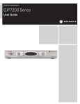
Front Panel
The front panel controls provide functional navigation if the remote control is lost or is temporarily out of service. Certain functions,
such as those requiring a numeric entry, require a remote control. Some connectors are not enabled and require the support of
application software.
1
2
3
4
5
REC
OK
POWER
QIP7200 2
1
USB connector
2
Cursor — 4-way menu navigation
3
Display Panel
4
Startup Indicator
5
Power — Turns the set-top on and off (standby)
Rear Panel
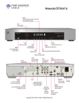
The rear panel contains a power outlet; connectors for video, audio, and RF cabling; data output; and data interface connectors. Some
connectors are not enabled and require the support of application software.
1
2
3
4
Y
5
7
Audio
Digital Audio
L
Pb
FiOS TV In
1
2
3
4
5
8
11
13
Removing card will
disable Set-Top Box.
Optical
Audio
R
Pr
RF TV Out
1394
Firewire
Video Out
S-Video
IR Remote
Input
eSATA
6
9
10
12
Reserved
14
15
POWER
16
1
FiOS TV In — Connects to FiOS signal from your service provider
2
RF Out — Ch 3/4 modulated audio/video (SDTV) to TV or VCR
3
IEEE-1394 — Audio and video device connection
4
YPbPr — Component video output (HDTV)
5
Audio — Composite Audio L/R outputs
6
Video — Composite Video (SDTV) output
7
Digital Audio (RCA)* — Provides Dolby® Digital 5.1 audio or PCM output
8
Optical Audio (S/PDIF)* — Provides Dolby® Digital 5.1 audio or PCM output
9
S-Video — Connects to S-Video (SDTV) input of TV or VCR
10
IR Remote Input — Connects to a remote control set-top accessory cable
11
HDMI — High-Definition TV (HDTV) connector
12
eSATA* — External Serial ATA disk interface (QIP7200 Only)
13
Ethernet* — Network connection
14
USB* 2.0 — High-Speed peripheral device connection
15
Reserved – Service only
16
Power cord connector — 3-prong AC outlet
*Feature is dependent upon application setting and availability in content
QIP7232 Quick Start Guide
2