1
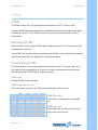
Operation Manual
SL6000 Series
Operating Manual
SL6000 Series
Contents
Introduction.......................................................... 5
Purpose of application notes .....................................................................5
Product description .....................................................................................5
Operating frequencies .................................................................................5
Feature List ..................................................................................................5
Warnings ......................................................................................................5
Unpacking information ...............................................................................6
Antenna installation ....................................................................................6
Battery pack installation .............................................................................7
Belt clip installation .....................................................................................7
Battery charging ..........................................................................................8
Programming ...............................................................................................8
Programming set-up ........................................................................9
Reading .............................................................................................9
Writing ..............................................................................................9
Cloning .............................................................................................10
Cloning set-up ..................................................................................10
SL6000 orthographic view ..........................................................................11
Mechanical radio operation ............................... 12
On/Off volume ..............................................................................................12
Accessory socket ........................................................................................12
Antenna socket ............................................................................................12
Push buttons ................................................................................................12
PTT ................................................................................................................12
Monitor key ...................................................................................................12
Emergency key ............................................................................................13
Function key .................................................................................................13
Up/Down keys (▼▲) ...................................................................................13
Power H/L key ..................................................................................13
Group key .........................................................................................13
Lamp/Lock key .............................................................................................13
Lamp key ..........................................................................................13
Page 2 of 27
Contents
Power/group key ..........................................................................................13
Operating Manual
SL6000 Series
Channel lock key .............................................................................14
Menu/Scan key .............................................................................................14
Menu key ..........................................................................................14
Scan key ...........................................................................................14
TX/RX/busy LED ...........................................................................................14
Basic radio operation......................................... 15
Channels .......................................................................................................15
Channel labels .............................................................................................15
Channel spacing ..........................................................................................15
Output power ...............................................................................................15
Beep mode ...................................................................................................15
Squelch options ...........................................................................................15
CTCSS ...............................................................................................16
DCS ...................................................................................................16
Monitor ..........................................................................................................16
Squelch level................................................................................................17
Busy channel lockout ................................................................................17
Mark idle ......................................................................................................17
TOT timer .....................................................................................................17
TX inhibit .....................................................................................................17
TX delay .......................................................................................................17
Penalty time ................................................................................................17
Emergency feature .....................................................................................18
VOX ...............................................................................................................18
Password protect .........................................................................................18
Scanning ........................................................... 20
Scan modes ..................................................................................................20
Normal scan .....................................................................................20
RX only scan ....................................................................................20
Priority scan .....................................................................................20
Look back .........................................................................................20
Transmitting during scanning .........................................................21
Normal scan TX ................................................................................21
Priority scan TX ...............................................................................21
Page 3 of 27
Contents
Scan channel delete ........................................................................21
Operating Manual
SL6000 Series
Priority only TX ................................................................................21
Group scan edit mode .................................................................................21
Group priority scan channel edit ...............................................................21
DTMF................................................................. 23
Receiving DTMF ...........................................................................................23
Transmitting DTMF ......................................................................................23
Function display ................................................ 24
PC programmer................................................. 25
Computer ......................................................................................................25
Operating System ........................................................................................25
Warning status messages ................................. 26
Contact details................................................... 27
Contents
Page 4 of 27
Operating Manual
SL6000 Series
Introduction
Purpose of application notes
The purpose of this document is to outline the functional features of the SL6000 Series
Handheld radio(s). This document will be used to navigate and set-up all of the
programmable features.
Product description
The SL6402/6102 is a fully featured handheld radio that has been developed for the
European market. The SL6402/6102 has features such as DTMF, emergency button and
password protect. It has a 208-channel capability and is small and light weight. The radio
is programmable for output power, channel spacing, and a range of other features.
Operating frequencies
RX
VHF V2
148.000-174.000 MHz
UHF U2
440.000-470.000 MHz
TX
148.000-174.000 MHz
440.000-470.000 MHz
Feature list
Group
CTCSS/DCS
Priority Lookback
VOX
Key lock
DTMF
Alpha numeric display
Emergency button
Cloning
Scanning
Hi/Lo power
Password Protection
Busy lockout
Page 5 of 27
Introduction
ANI
Operating Manual
SL6000 Series
Warnings
WARNING - DO NOT hold the radio in such a manner that the antenna is next to, or
touching, exposed parts of the body, especially the face or eyes, while transmitting.
WARNING - DO NOT allow children to operate transmitter-equipped radio equipment.
CAUTION - DO NOT operate the radio near unshielded electrical blasting caps or in an
explosive atmosphere unless it has been especially designed and qualified for such use.
CAUTION - DO NOT press and hold the transmit button (PTT) when not actually wishing
to transmit.
WARNING – only use authorised Maxon accessories with this radio. Using other
manufacturer’s accessories could damage the radio and invalidate the warranty.
WARNING - Never modify a radio, or accessory, except as instructed in the Service
Manual, Engineering Bulletins or formal communication as this may invalidate any
warranty, guarantee or type approval.
CAUTION – Operation of the transmitter without a proper antenna installed may result in
permanent damage to the radio.
Unpacking information
Remove and carefully inspect the contents of your package(s) for the following items:
Radio
Battery Pack
Battery Charger
Battery Charger Power Supply
Antenna
Spring Belt Clip
Operating Instructions
Page 6 of 27
Warnings
If any items are missing, please contact your Dealer or MaxonCIC.
Operating Manual
SL6000 Series
Antenna installation
Fasten the antenna to the radio by turning the antenna clockwise into the receptacle on
top of the radio making sure the antenna is tightly locked in place. Do not over tighten the
antenna.
Installing and removing the battery pack
To Install:
Position the guides of the battery in line with the radio battery guide rails and slide the
battery into position until a click is heard.
Holding radio in one hand, push and hold battery latch button located at the bottom of the
battery pack and radio. Hold radio firmly and slide battery in downward direction while
pushing the battery latch button.
Page 7 of 27
Antenna and Aerial Installation
To remove:
Operating Manual
SL6000 Series
Attaching and removing the belt clip
To Install:
Install belt clip onto the belt clip holder located on the upper part of the battery, held with
the at the back of the unit facing upwards. Locate slot location in belt clip and push belt
clip until a click is heard.
To remove:
Push and hold release button located at top of belt clip and slide clip off the belt clip
holder.
Battery charging and care
To ensure peak performance from your radio, the battery pack must be fully charged.
Proper care and charging will allow maximum performance and life of your battery pack.
CH-SL6000-01 Desktop Charger provides 2 hour charging.
SL6000-01 charger specification
1) input voltage: DC12V Normal
2) Input voltage range: DC10.5~15V
3) Input Current 1.0A max at Full load
Programming
Please refer to the SL6000 Series Programming manual for detailed programming
information.
The programming kit required is the PR- SL6000-01
Kit consists of
PK-SL6000-03 programming software
To place the SL6402/6102 into program mode, connect PK-SL6000-01 programming lead
to the PC and the SL6402/6102 via 3.5mm stereo jack connector (please see top panel
layout Fig.3). To enter the radio into programming mode, press and hold the monitor
button and switch radio on. Let go of monitor when “PC Programmer” is displayed on LCD.
The radio is now in programming mode and is ready to take serial commands from the
PC.
Page 8 of 27
Battery Charging
Programming lead PK-SL6000-01
Operating Manual
SL6000 Series
Programming set-up
PC
PK-SL6000-01
SL6402/6102
(Fig. 1)
Reading
When serial read commands are sent though the interface leads from the PC Programmer
to the radio, SL6402/6102 will transmit the data. During this sequence, the Red LED will
stay solid red. In Reading Mode, the LCD displays “READING”. When reading has
finished the LCD display will read “COMPLETED”.
Writing
When serial write commands are sent though the interface leads from the PC Programmer
to the radio the PC then starts the transmission of data. During this sequence, the green
LED will stay solid green. In the PC program Writing Mode, the LCD displays “WRITING”.
When writing has finished the LCD display will read “COMPLETED”.
Programming
Page 9 of 27
Operating Manual
SL6000 Series
Cloning
The SL6402 radio requires the cloning cable. The frequencies and functions can be
programmed from radio to radio by using a cloning cable.
Ensure that both radio’s power is in the switched “OFF” position.
Place the master radio (the radio which already has desired program information in the
EEPROM) in the data master mode by holding the radio’s monitor switch and then turning
radio power switch to the “ON” position (the red LED on the radio flashes). Release the
monitor switch on the third led flash (the radio will display “MASTER” message on the
LCD).
Place the slave radio (the radio which is not programmed, or has program information that
will be erased) into data slave mode by holding the radio’s monitor switch and then turning
the radio power switch to the “ON” position (the red LED on the radio flashes). Release
the monitor switch on the second led flash (the radio will display “SLAVE” message on the
LCD).
Connect the cloning cable through accessory socket.
Press the slave radio’s monitor switch. The LED will glow green.
Press the master radio’s monitor switch. The LED will glow red and cloning will start.
After cloning, the slave radio displays "COMPLETED" message and the master radio
displays “MASTER” message on LCD.
For cloning other radios, repeat above procedure.
Cloning set-up (Fig.2)
Page 10 of 27
PK-SL6000-02 cloning lead
Slave
Cloning
Master
Operating Manual
SL6000 Series
SL6000 orthographic view
(Fig.3)
1
Accessory Connector
9
Group / Power Button
2
On/Off - Volume Control
10
Lamp / Lock Button
3
Tri-coloured LED Status Indicator
11
Menu / Scan Button
4
Antenna Receptacle
12
LCD
5
Belt Clip
13
Channel Selector Buttons
6
Push-To-Talk (PTT)
14
Microphone
7
Monitor Button
15
Speaker
8
Emergency Button
16
Battery Charge Contacts
Page 11 of 27
SL6000 Orthographic View
Description of radio mechanical component
Operating Manual
SL6000 Series
Mechanical radio operation
On/off volume
The On/Off volume is a potentiometer located on the top left-hand side of the radio.
Rotating the knob clockwise past the détente turns the radio on and increases the audio
volume up to the maximum volume level. Rotating the knob anti-clockwise decreases the
audio volume. Rotating the knob anti-clockwise past the détente will turn the unit off.
This volume knob also controls the volume to external speakers.
Accessories socket
The accessories connector (3.5mm stereo socket) allows for an external microphone
and/or external speaker. The connector also provides a means of programming via a PC
serial port.
Antenna socket
Care should be taken when removing or fitting the antenna. The socket is an SMA
connection. Do not over tighten when fitting the antenna.
Push buttons
top to bottom, they are: PTT (protruded dots raised profile), Monitor (raised profile).
Emergency (Orange with flush profile). They allow the following features:
PTT (Push to Talk)
PTT (Press to Talk) – This button enables the radio to transmit. Also used for enter button
when used with menu.
Monitor key (Squelch Defeat Operation)
By pressing the middle side button (monitor), the user can override the programmed
squelch operation and un-mute the speaker on the selected channel. Not only will activity
on that frequency be heard but ‘white noise’ will also be heard. When the user releases
the Monitor key, the radio will resume programmed squelch operation.
Page 12 of 27
Mechanical Radio Operation
The three buttons located on the left-hand side of the radio, are described as follows; from
Operating Manual
SL6000 Series
Emergency key
The Emergency function is initiated when the lower orange side button is pressed; a preprogrammed DTMF ANI sequence is sent. Three ANI calls followed by a string of eleven
sets of audible tones will be heard. A 3 second press/hold is required to enable an
emergency call.
Function keys
There are five push-buttons on the front of the SL6402/6102; ▼▲, Menu/Scan Button key,
Hi Low Power/Group key, and Lamp/Key Lock key.
Up/Down keys (▼▲)
These buttons allow the operator to scroll up/down through the available channels. A short
press/release of this button will increase/decrease the channel number. A press-and-hold
will scroll through the channel numbers. These buttons are also used to traverse through
the menu choices.
Power/Group key
Power H/L key
Short Press to toggle the transmit output power between High and Low.
Each channel can be programmed via the PC programmer to be high or low power. The
output, 2 Watt.
Group key
A long 3 second press/hold will allow the user to select a group of channels if pre
programmed. Press Group key for 3 sec. until “Group” is displayed. Use (▼▲) to select
correct group of channels. To activate group press PTT. Up to 13 groups can be selected
if pre-programmed.
Lamp/Lock Button
Lamp
A short press of the lamp key will illuminate the five front buttons and the LCD for 10
seconds and switch off.
Page 13 of 27
Mechanical Radio Operation
power can also be changed by the user to high-power output 5 Watts, and a low-power
Operating Manual
SL6000 Series
Lock
A long 3 sec. press on the Lamp/Lock Button will disable the ▲▼ keys. This feature also
locks the H/L/group key and Menu/Scan Key. Please note the PTT, Monitor and
Emergency keys are still operational.
Menu/Scan key
Menu key
The Menu key together with the ▲▼ keys are used for scrolling through the available
features (please see table below). A long 3 second press of the menu button will display
the first feature of the available options. Once the correct function has been selected use
the ▲▼ keys to change the settings of the parameter. To save the settings press the PTT
button.
Function
Beep
DTMF
Password
Squelch Level
Settings
Display
Global bleeps
On/Off
Beep On / Off
On/Off
Dtmf On / Off
On/Off
Pswd On / Off
Used to activate any programmed
DTMF functions.
User can not activate the radio until the
correct password has been entered.
Circuit designed to mute the speaker
Level can be set from
when a very weak signal is received.
1–10 Secs.
Voice operated Transmit.
On/Off
SQLy (1 – 10) S
Vox On / Off
(Fig.4)
Scan key
The Scan Key is used for activating the scanning feature depending on programming. For
more information on scanning please see the Scanning Section.
TX / RX / busy LED
TX / RX / Busy LED is a tri-colour LED (Red, Green, Amber and OFF) and has multiple
states to indicate the status of the radio. Red -TX, Amber - busy, Green – correct carrier +
CTCSS / DCS
Page 14 of 27
Mechanical Radio Operation
Vox
Description
Operating Manual
SL6000 Series
Basic radio operation
Channels
The SL6000 Series radio(s) can store up to 208 channels within the same frequency band.
These channels can be selected by using the▼▲ keys. The channels can all be
programmed using the SL6402/6102 programmer. The SL6000 is capable of up to 13
programmed groups with up to 16 channels per group. A press and hold of the▼▲ keys
will scroll through your programmed channels. Channel numbers will appear in the LCD
located at the top of the unit. If your radio has been programmed for Channel Group Scan
you must enter the scan mode by pressing the scan button which is located beneath the
LCD. The Channel Group to be scanned will be shown in the display. In order to change
the Channel Group press the ▼▲ keys to select desired group to be scanned.
Channel Labels
The SL6000 Series is capable of displaying up to 32 channel labels. Up to eight
characters can be displayed on the LCD. A different label can be displayed on each of the
32 channels. This is a PC programmable feature only.
Channel spacing
The SL6000 is capable of programmable channel spacing. Each channel can be
programmed to 12.5 KHz or 25 KHz channel spacing using the PC programmer.
Output power
Watts, and a low-power output, 1 Watt. The power can be switched by the user High / Low
by Pressing the H/L key.
Using the APC (Automatic Power Control) software the exact RF power can be adjusted
for low and high power settings.
Beep On/Off mode
All Beep tones can be globally enabled or disabled via the PC programmer.
Page 15 of 27
Basic Radio Operating
Each channel can be programmed via the PC programmer to a high- power output 5
Operating Manual
SL6000 Series
Squelch options
The Radio supports 2 kinds of squelch options. A different squelch option can be applied
to each channel. Sub Audible Tone (SAT) codes are made up from frequencies which are
below 300Hz. These frequencies are lower than the voice audio band. The two most
common forms of SAT codes are CTCSS, Continuous Tone Coded Squelch System, and
DCS, Digitally Coded Squelch.
CTCSS/DCS information may be added to speech during transmission. A receiving radio
can then be programmed to behave according to which tones or codes are being sent by a
transmitting radio.
The SL6000 Series radios are capable of generating all 47 standard CTCSS tones and
can also generate the 83 standard DCS codes and 83 inverted DCS codes.
CTCSS
47 kinds of TIA/EIA Standard CTCSS Tones can be set up. All tones can be set up using
PC Programmer.
TX Operation: If PTT key is pressed, the radio transmits programmed CTCSS tone.
RX Operation: If CTCSS Tone is detected, the Radio status is changed from Busy to
Correct Call. If the CTCSS Tone is not detected, the radio would stay in Busy mode or
change from Correct Call to Busy mode.
DCS
The radio supports 83 kinds of TIA/EIA Normal/Inverted DCS codes.
TX Operation: If PTT key is pressed, the Radio transmits pre-programmed DCS Bit
RX Operation: If DCS Data Stream is detected, the radio status will change from busy
mode to correct call. If DCS data stream is not detected, the radio will stay in busy mode
or be changed from correct call back to busy mode.
Monitor
Squelch defeat operation
Pressing the monitor key will open the squelch and switch on the loudspeaker. Everything
on the channel, including FM noise, will be heard.
It is possible to disable the monitor key via the programmer, to prevent a user openly
monitoring a channel in a closed user group system.
Page 16 of 27
Basic Radio Operating
pattern.
Operating Manual
SL6000 Series
When using CTCSS or DCS controlled squelch, several user groups may use the same
RF channel without overhearing the other groups. It is common practice to allow users to
listen to a channel before placing a call. This allows the user to check they are not going to
transmit over a conversation from another user group.
This allows more efficient use of the RF channels available.
Squelch level
The squelch level can be adjusted either by the PC programmer or by the user. By setting
the level high i.e. 10 the radio will open with a higher level of noise.
Squelch Level (N Band) 1-10
Squelch Level (S Band) 1-10
Busy channel lockout
The radio has several inhibit functions which restrict transmission under the following
conditions:
Busy Channel Lockout – ON: Upon PTT being pressed, if carrier is present, the radio shall
not transmit and an audible alert tone will be heard.
Busy Channel Lockout – OFF: Upon PTT being pressed, the radio shall transmit
regardless of the presence of carrier.
Mark idle
Marked Idle enabled: Can only be enabled if Busy Channel Lockout is ON. If the Busy
option is valid.
TOT timer
Once the TOT has been enabled, the PTT Timer can be set from 0 – 990 seconds with 10
second increments, which is the allowed time for a sustained transmission.
Penalty time
The penalty timer does not allow a transmission for a set programmed time after the PTT
timer has expired, to allow a cool off period for the transmitter. The settings are from 0 –
75 s in 5 sec. increments.
Page 17 of 27
Basic Radio Operating
Channel Lockout is on and carrier is detected, the radio permits transmit if the RX squelch
Operating Manual
SL6000 Series
Emergency feature
The emergency function is initiated when the lower orange side button is pressed; a preprogrammed DTMF ANI sequence is sent. Three ANI calls are sent, followed by a five
seconds of audible tones. A 3 sec hold/press is required to enable an emergency call.
The emergency feature can also be programmed to transmit on either a user define
frequency or the current channel. The emergency beep value can be set high or low.
VOX (voice operated transmit)
Voice operated transmit is activated when audio is detected at the microphone, without
pressing the PTT key.
The radio can transmit with low and high voice levels in accordance with VOX level 1~9.
VOX delay Time 0.5sec to 3sec. in 0.5 increments. This is the time delay at the end of
VOX operations.
This function is set with PC program or using the menu mode. Long press the Menu
button until radio enters menu mode, short press menu button until menu reaches VOX
menu mode. To activate VOX feature press ▲▼ and set Vox on/off then save by pressing
PTT.
To change the voice activation level follow above procedure, once VOX has been
activated press menu again and set level using ▲▼, then save by using the PTT.
Note: When power is switched off the feature will return to default settings.
Overview
This function can be set to prohibit unauthorised usage of the unit. When the password is
enabled, a 4 digit password code is required to be entered at power up.
Enable and Disable password function
To enable the password function of the unit, press and hold the Menu button for 2
seconds. The LCD display will change to show the available menu's. Using the menu
button, press the menu button until "Pswd Off", is displayed. To enable the password use
the channel ▼▲buttons until "Pswd On" is displayed.
To disable the password, repeat the above.
Page 18 of 27
Basic Radio Operating
Password protect
Operating Manual
SL6000 Series
How to enter the password
To add the password, switch on the unit, briefly the word Password is displayed on the
unit, then is replaced by 0000 (4 zero's). A ª symbol is positioned above the 1st zero (left
hand zero); this signifies that this digit is the first of the Password digits to change. Using
the ▼▲arrow keys, select the first number of the Password, then press the PTT button to
store the number. As the PTT is pressed, the arrow moves one digit to the right, now enter
the second number of the password, and again save the number by pressing the PTT
button. Continue to repeat this process for digits 3 and 4.
There is no limit on password entry attempts
Once the PTT button is pressed after the 4th number, the unit will accept or decline the
Password.
Warning Note: - if Password is forgotten, then the unit must be reprogrammed by a
Maxon authorised reseller.
Basic Radio Operating
Page 19 of 27
Operating Manual
SL6000 Series
Scanning
Scan modes
Scanning is a Dealer programmable feature that allows you to monitor a number of
channels or channels within a group. Your Dealer will help you define your "scan list"
Normal channel scan
During programming of the radio, any channel can be selected as a channel to be
scanned. A short press on the Menu/Scan button, on the front of the radio will activate
scanning. While the radio is scanning, the LED indicator flashes green. Once scan is
activated, the radio will traverse through the pre-programmed scan list. The time spent on
receiving a channel in the scan list is referred to as the scan speed time. When an
incoming call is detected and decoded, scanning stops and the radio enters Correct Call
Mode and the speaker is active. After the call has ended, the radio stays active for a preprogrammed period which is defined by the scan wait time. If the radio receives a call from
the same caller before the scan wait time expires, the radio remains in Correct Call Mode
and the scan wait time is reset. When the scan wait time expires, the radio resumes
scanning.
Priority channel scan
This function operates only when priority channel is set via the SL6000 Series
programmer. During programming of the radio, any one channel can be selected as the
priority scan channel. The priority channel will be included on the list of channels that
make up the scan list. The priority channel when used with other scanned channels
operates as follows: P1→S1→P1→S2→P1→S3→P1→S4→P1, etc.
If you try to TX on priority scanning, the radio transmits according to TX options set by the
PC programmer (see Transmitting during scanning). Press the scan button to exit this
function.
Lookback
This function allows the radio to scan between priority channel and lookback channel.
When the current channel is the look back channel, the Priority Look back Scan
priority channel). Lookback channel is displayed as an “L” Icon on the LCD. Lookback
channel is set by the PC Programmer.
Page 20 of 27
Scanning
automatically starts. Scan channel operates on 2 channels (current lookback channel and
Operating Manual
SL6000 Series
Scan channel delete: To temporarily delete a channel from the scan list, simply press
the G/H/L button while scanning and stopped on the channel to be deleted. This will
temporarily remove that channel from the scan list until the channel is changed or the
radio's power is reset. When power is restored or the scan list channel position is again
selected, the scan list will revert to it’s original settings.
Transmitting during scanning
The radio is set to behave in a number of ways when the PTT is pressed during scan.
Normal scan TX – Radio will only transmit on a stopped channel i.e. to return a call.
Attempting to transmit during scanning will cause a warning alert.
Rx only, no TX – No transmissions are allowed during scanning. If transmission is
attempted a warning tone will be sounded.
Priority scan TX – The radio can be set to transmit on the channel on which activity has
been detected -OR- transmit on the priority channel if scanning is still active.
Priority only TX – If scanning, or listening to an active channel, and the PTT button is
pressed, the radio will only transmit on the priority channel. No transmit conditions will be
permitted. If transmission is attempted, a warning tone will be sounded.
Group scan list edit
You can edit your pre-programmed Group Scan List via the radio or by adding or deleting
channels from the group scan list.
To activate scan list editing, press the Menu button until the radio enters ‘Scan List Edit
Mode’. Upon entering ‘the Scan List Edit Mode’, the LCD will indicate the “ScnL”
message. To exit the scan list edit function, Press the PTT.
The radio displays the scan channel number by ‘S’ Icon on or off. You can change the
scan channel by using the ▼▲buttons. To add or delete this channel from the scan list,
press the monitor button. When added, the ‘S’ Icon will be displayed on the LCD display
window. When deleted, the ‘S’ Icon will disappear from the LCD.
You can edit your pre-programmed group priority channel via the radio, by adding or
deleting channels from the group scan list.
Page 21 of 27
Scanning
Group priority channel edit
Operating Manual
SL6000 Series
To activate priority channel editing, press the Menu/Scan button until the radio enters
‘Priority channel Edit Mode’. Upon entering ‘the Priority channel Edit Mode’, the LCD
displays “Pscn”. To exit the priority channel edit function, Press the PTT.
The radio will display the priority channel number with ‘P’ Icon on or off. You can change
the priority channel by using the ▼▲buttons. To change the priority channel, press the
monitor button. If selected the priority channel, the ‘P’ Icon is displayed on the LCD display
window. When deleted, the ‘P’ Icon will disappear from the LCD.
Scanning
Page 22 of 27
Operating Manual
SL6000 Series
DTMF
DTMF
The DTMF feature is PC programmable and attached to the PTT (Press to Talk).
Once the DTMF ANI (Automatic Number Identification) has been pre-programmed, ANI is
encoded on every PTT. The DTMF call can be set up to be sent at the start or end of
transmission.
Receiving DTMF
When a DTMF code is received DTMF data is displayed on the LCD. Five characters can
be displayed on the LCD.
If the DTMF code is longer than five characters the SL6402 / 6102 will decode and display
the first five characters, then display any remaining characters.
Transmitting DTMF
The DTMF feature is PC programmable and attached to the PTT (Press to Talk). Up to
five digits can be pre-programmed. There are a number of parameters that can be set
associated with the DTMF Feature. Please see below.
DTMF type
Standard DTMF or Non Standard.
DTMF mark - space time
This is the length of each of the DTMF tones transmitted. 65:50 or 55:50.
1209 Hz
1336 Hz
1477 Hz
1633 Hz
697 Hz
1
2
3
A
770 Hz
4
5
6
B
852 Hz
7
8
9
C
941 Hz
*
0
#
D
DTMF Gen time
Time taken to generate the tone 340/240
ms.
The DTMF code can either be sent at the
start or the end of the call.
DTMF
Page 23 of 27
DTMF out time
Operating Manual
SL6000 Series
Function display
12345678
Transmitting Icon
* Hi power: Antenna bar is full.
* Low power: Antenna bar is 3.
Receiving Icon Change antenna bar 0~5 by
receiving signal sense.
P: current channel is priority channel.
/
L: current channel is lookback channel.
Vox: Voice operated transmit
S: Current channel is scan
channel
T: Current channel has a sub tone.
/
L: TX power is low.
This icon is displayed if there is a group.
Page 24 of 27
Function Display
H: TX power is high
Operating Manual
SL6000 Series
Display when DTMF is set.
Display when beep is on.
Displayed when key lock option is
on.
Displays charge level of battery.
PC programmer
Computer
Pentium II processor or later (recommended)
Microsoft Windows 98, 2000, NT, XP
Page 25 of 27
Function Display
Operating system
Operating Manual
SL6000 Series
Warning status messages
Status
Normal
LED colour
LCD indication
Power On - Ready
N/A
Channel number
Melody
Call Received
Orange
Channel number
N/A
Correct Call
Green
Channel number
N/A
Busy Channel
Orange
Channel number
N/A
Transmit
Red
Channel number
N/A
Transmit not
allowed
Scanning
Normal Scan mode
Priority Scan Mode
Scan Edit
Priority
Warning
Edit scan list
Edit priority
channel
Low Battery
Busy Channel
lockout
TX Inhibit
Page 26 of 27
Red Flashing
Green
Alternating UL/Channel
number
tone
Two bleeps
Group number
N/A
N/A
Scan
N/A
N/A
Pscn
N/A
Red Flashing
Low_BATT
3 beeps
orange
Busy-Lock
Single bleep
N/A
PENALTY
Two bleeps
Flashing
Green
Flashing
Warning Status Messages
Edit
Audible
Description
Operating Manual
SL6000 Series
Contact details
Should you have any queries regarding this manual, or the information in it, please
contact:
Maxon House,
Cleveland Road,
Hemel Hempstead,
Hertfordshire,
United Kingdom,
HP2 7EY
Tel: + 44 (0) 1442 267 777
Fax: + 44 (0) 1442 215 515
[email protected]
www.maxoncic.co.uk
Technical Support:
Tel: + 44 (0) 1442 226 170
Email: [email protected]
Customer and Sales Support:
Telephone: + 44 (0) 1442 267 777
Email: [email protected]
Repairs:
Tel: + 44 (0) 1442 267 777
Page 27 of 27
Contact Details
Email: [email protected]