1
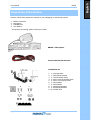
PM200 Table of Contents Table of Contents .................................................................................................................1 Specification .........................................................................................................................3 About Your PM200 Radio ..............................................................................................3 Safety Information ................................................................................................................4 Unpacking Information ..........................................................................................................5 PM200 Features & Description................................................................................................6 Product Description ......................................................................................................6 Front and Rear panels ...........................................................................................................7 Front panel layout ........................................................................................................7 Rear panel layout .........................................................................................................7 Front and Rear descriptions ...................................................................................................8 LCD Display ..........................................................................................................................9 Basic Radio 0peration .......................................................................................................... 10 On/Off Volume Control ............................................................................................... 10 Channels ................................................................................................................... 10 Output Power ............................................................................................................ 10 Beep On/Off Mode ..................................................................................................... 10 Public Address ........................................................................................................... 10 Internal Speaker and External Audio Switch.................................................................. 10 Microphone Hook ....................................................................................................... 10 Squelch Options ......................................................................................................... 11 CTCSS ......................................................................................................................... 11 DCS ............................................................................................................................ 11 Squelch Defeat (Monitor) operation................................................................................ 11 Muting Options .......................................................................................................... 12 PTT Timer ................................................................................................................. 12 TX Inhibit .................................................................................................................. 12 TX Delay ................................................................................................................... 12 Busy Channel Lockout ................................................................................................ 12 Marked Idle ............................................................................................................... 12 PTT Lockout .............................................................................................................. 12 Display Logo .............................................................................................................. 13 Power up Alert ........................................................................................................... 13 Scanning ................................................................................................................... 13 Normal Scan .............................................................................................................. 13 Priority Scan .............................................................................................................. 13 Priority Look Back Scan............................................................................................... 13 Transmitting During Scanning ..................................................................................... 14 Scan Channel Delete .................................................................................................. 14 Group Scan Edit Mode ................................................................................................ 14 Priority Scan Channel Edit ........................................................................................... 14 Basic programmable features ............................................................................................... 15 Function Keys ............................................................................................................ 15 Up/Down Keys (▼▲) ................................................................................................. 15 Programmable Function Keys ...................................................................................... 15 Power key ................................................................................................................. 15 Light Key ................................................................................................................... 15 Monitor Key ............................................................................................................... 16 Lock Key ................................................................................................................... 16 Scan Key ................................................................................................................... 16 Public address Key ..................................................................................................... 16 Open/Close Key ......................................................................................................... 16 Selcall Key ................................................................................................................. 16 SMS Key .................................................................................................................... 16 Page 1 English User Manual User Manual PM200 1200/2400 bps Key .................................................................................................... 16 DTMF Key.................................................................................................................. 16 Group Key ................................................................................................................. 16 Emergency Key .......................................................................................................... 17 Status and Error Messages................................................................................................... 18 Service Information............................................................................................................. 19 Page 2 PM200 Specification English User Manual About Your PM200 Radio Maxon's PM200 Series radio features 208 channels. Operation and functions of these radios are outlined in this manual. We urge you to thoroughly read this manual before operating the radio The application of some of the functions described in this manual is determined by the system you use. Your Maxon Dealer will program your radio so that you have the greatest number of functions possible relative to your needs. Performance Specifications R&TTE Directive 1999/5/EC ETSI EN 300 086-1/-2 EMC Directive 89/336/EEC ETSI EN 301 489-1/-5 LV Directive 73/23/EEC EN 60950-1 72/245 EC as assembled by 2004/104/EC (UHF) 440.000 – 480.000MHz (VHF) 148.000 – 174.000MHz Channel Spacing 12.5 kHz, / 25 kHz (12.5 / 25 kHz switchable by CPU control) RF Output Power PM200 RF Output Power PM250 2W - 25W nominal (+/-20%) 5W - 45W nominal (+/-20%) Modulation Type F3E/G3E Audio Power 4W (Internal 16 Ω speaker) Intermediate Frequencies 45.1MHz First I.F. 455 kHz Second I.F. Number of Channels 208 Channels Frequency Source PLL Synthesiser Frequency Stability +/- 2.5ppm Power Supply 13.8Vdc nominal 10.8Vdc minimum (extreme) 15.6Vdc maximum (extreme) Current Consumption OFF <10µA Standby (muted) <140mA Unmuted with 25% AF power <350mA Unmuted with 50% AF power <450mA Unmuted with 100% AF power <1000mA Transmit @ 2W RF output <2.0A Transmit @ 25W RF output <7.0A Page 3 Specification Frequency coverage PM200 Safety Information English User Manual 1. WARNING! NEVER connect the transceiver to an AC outlet. This may pose a fire hazard or result in an electric shock. 2. NEVER operate the radio transmitter without a suitable artificial load or antenna connected. 3. NEVER connect the transceiver to a power source of more than 16V DC such as a 24V battery. 4. NEVER cut the DC power cable between the DC Plug and fuse holder. If an incorrect connection is made after cutting, the transceiver may be damaged. 5. NEVER place the transceiver where normal operation of the vehicle may be hindered or where it could cause bodily injury. 6. NEVER expose the transceiver to rain, snow or any liquids. 7. NEVER modify a radio or accessory except as instructed in the service manual, engineering bulletins or formal communication as this may invalidate any warranty, guarantee or type approval. 8. USE the supplied microphone only. Other microphones have different pin assignments and may damage the transceiver. (ACC-700, optional DTMF MIC. ACC-703) 9. DO NOT use or place the transceiver in areas with temperatures below -30ºC or above +60°C in areas subject to direct sunlight, such as the dashboard. 10. AVOID operating the transceiver without running the vehicle’s engine. The vehicle’s battery will quickly run out if the transceiver transmits while the vehicle’s engine is OFF. 11. AVOID placing the transceiver in excessively dusty environments. 12. AVOID the use of chemical agents such as benzene or alcohol when cleaning, as they damage the transceiver surfaces. 13. BE CAREFUL! The transceiver will become hot when operating continuously for long periods. 14. DO NOT operate this equipment in environments containing explosive materials or vapors. Warnings Page 4 PM200 Unpacking Information English User Manual Remove and carefully inspect the contents of your package(s) for the following items: 1. 2. 3. 4. PM200 Transceiver Microphone Installation kit User Manual * If any items are missing, please contact your Dealer PM200 + Microphone Power lead with 10 amp fuse Installation kit 3 2 Page 5 4 5 6 7 8 9 1. 2. 3. 4. 5. 6. 7. 8. 9. 10. 1 1 2 2 2 2 2 2 2 4 x x x x x x x x x x Fixing bracket Microphone bracket Thumb wheel screws M3 x 6mm Mic bracket Screw M5 x 11mm fixing screws M3 Washers M5 Washers M3 Spring Washers M5 Spring Washers Rubber feet Unpacking information 1 PM200 PM200 Features & Description English User Manual 2W or 25W Programmable output power 208 Programmable Channels D-SUB 15Pin Data Connector Programmable 12.5 /25 KHz Channel Spacing Channel Scan Priority Channel Scan Look Back Channel Scan List Edit Priority Channel Edit CTCSS/DCS/DTMF tone signalling Busy Channel Lock-out Mark Idle Time out timer Public Address SELCALL Stun and Revive Covert Mode ANI SELCALL Messaging Acknowledge Key Lock Start up Definable Logo Auto Mute Back Light Display SMS DTMF HOOK Switch Product Description The PM200/250 is a fully featured mobile radio that has been developed for the European market. The PM200/250 is a DTMF, Selcall and SMS mobile radio with a 208-channel capability. The radio is programmable for output power, channel spacing, and a range of other features. Page 6 Feature List The PM200 mobile radios are packed full of sophisticated user and system features which allow the radios to be tailored to meet the requirements of most radio networks today. All the features described are made available thanks to the latest reliable, but functionally rich, software that controls each PM200 mobile. This means that all features described are available without the need to fit expensive and time consuming option boards. Most of the features or options described are activated in the radio as programmable parameters; please contact your dealer for full details on these options. The PM200 is a DTMF, SECALL and SMS mobile radio with 208-channel capability. The radio is programmable for output power, channel spacing, and a range of features. The three buttons located on the bottom left-hand side of the radio under the LCD, are described as programmable. These three buttons (P1, P2, and P3) have a short and long press and can be used for various pre- programmed features, Monitor, Power H/L, Scan, DTMF, Key lock, Selcall, Scan, Public Address, Open Close, 1200/2400, SMS and Light. The range does conform to R+TTE Directive. The unit meets the R+TTE Directive ETS 300.086 2001. Front and Rear panels PM200 English User Manual Front panel layout 1.) RJ45 Microphone Socket 2.) On/Off Volume Control 3.) Alpha Numeric LCD 4.) (P1-P3) Programmable Keys 5.) Status LED 6.) Emergency Key (Orange) 7.) Up/Down Channel/Menu Keys 8.) Internal Speaker Rear panel layout 10.) 15 way D-type (programming/cloning) 11.) GPS antenna port (Optional) 12.) DC power lead 13.) Accessory Socket Page 7 Front and Rear Panels 9.) BNC Antenna Connector PM200 Front and Rear descriptions English User Manual 1. Microphone socket Connect the supplied microphone or optional DTMF/Heavy Duty microphone. NEVER connect non-specified microphones the pin assignments may be different and the transceiver may be damaged. 2. Volume control switch To turn the radio ON and OFF, rotate the knob clockwise ON and anticlockwise to turn OFF. Rotate the knob to adjust the audio output level up and down. 3. LCD Display Displays a variety of information such as an operating channel number, SELCALL Number, DTMF number and Volume level, etc. NOTE: The above functions depend on programming. 4. Dealer programmable keys (P1) to (P3) Desired functions can be programmed independently by your dealer. 5. LED Indicator Indicates radio condition from LED colour (see status and indicator and alert tones in section 6.) 6. Emergency key Transmits emergency call 7. Up/Down keys Push to select the operating channel. Rear View description 9. BNC Antenna connector Connects to an antenna. Contact your dealer about antenna selection and placement. 10. D-SUB 15Pin Connector Connect DB-9 and DB-15 connector of PK-PM200/250-01 to the PC and radio for programming. 11. External Speaker Jack Connect an 8 - 16Ω external speaker, if desired 12. GPS Antenna Tube Space for a GPS antenna and internal connectors have been included for customer applications. 13. DC Power Receptacle Connects to a 12V Dc battery 13.8Vdc nominal 10.8Vdc minimum (extreme) 15.6Vdc maximum (extreme). Page 8 Basic Radio Descriptions 8. Internal Speaker Note: Internal and external speakers can be switched by holding in the P1 and P3 buttons during radio switch on. The display will indicate which state the radio is in. PM200 LCD Display 1 2 3 5 6 P 4 7 L 8 9 English User Manual 0 1.) Signal strength indicator: Indicates relative signal strength level. 2.) TX Indicator: Appears while transmitting. 3.) Scan Indicator: Appears at the scan Channel. 4.) P Scan Indicator: Appears at the Priority scan Channel. 5.) Key Lock Indicator: Appears when the key lock function is on. 6.) Speaker Indicator: Appears when in the monitor mode. 7.) Low Power Indicator: Appears when low output power is selected. 8.) Selcall Detect Indicator: Appears when the selcall code is received. 9.) Currently not used. 10.) Currently not used. The LCD can display Alpha numeric characters and can be scrolled using the programmerable (P1) – (P3) keys. Short message service Text can be sent and displayed by the PM200. Selcall numeric codes stun and revive and error messages can also be displayed. LCD Display Page 9 PM200 Basic Radio 0peration English User Manual Before beginning operation of the product please insure installation has been carried out by a qualified engineer. Make sure connections power, antenna and microphone have been fitted correctly On/Off Volume Control Turn the radio on by rotating the off/on/volume control clockwise. You will hear a click and (if enabled via dealer programming), the radio’s self-test alert tones. Increase the radio volume by continuing the clockwise rotation. To turn the radio off, rotate the control anti-clockwise until a click is heard. Channels The PM200/250 Series radio can store up to 208 channels within the same frequency band. These channels can be selected by using the ▼▲ (up/down) keys. The channels can all be programmed using the PM200/250 programmer. Output Power Each channel can be programmed via the PC programmer to a high-power output of 25 Watts, and a low-power output of 2 Watts. The power can be switched by the user High / Low by pressing pre-programmed power key (P1-P3). Beep On/Off Mode All Beep tones can be globally enabled or disabled via the PC programmer. Public Address When selected and external speaker is attached, the radio will output voice audio over the external speaker. The radio does not TX a carrier in this mode. P/A will be shown in display when selected. When active allows operator to enable an external speaker and transmit microphone audio only. Internal Speaker and External Audio Switch The internal speaker and external accessory socket can be manually switched by the user. This P1 and P3, Switch radio on. Display will read either External or Internal. Microphone Hook This is a PC programmable function. Turned OFF, the user is not required to ground microphone button on to the Mic hanger. All decode and scan functions remain the same. Turned ON, the user is required to ground the microphone hook. When microphone is removed from ground all tone decode functions are disabled, scan functions are programmable as on or off with microphone removed from hook. Default is off with scan disabled. Page 10 Basic Radio Operation can be changed by the PC programmer. With the radio switched off hold in programmable keys PM200 Squelch Options The radio supports 3 kinds of Squelch options. A different Squelch option can be applied to each English User Manual channel. Sub Audible Tone (SAT) codes are made up from frequencies which are below 300Hz. These frequencies are lower than the voice audio band. The two most common forms of SAT codes are CTCSS, Continuous Tone Coded Squelch System, and DCS, Digitally Coded Squelch. CTCSS / DCS information may be added to speech during transmission. A receiving radio can then be programmed to behave according to which tones or codes are being sent by a transmitting radio. The PM200/250 radios are capable of generating all 38 standard CTCSS tones and can also generate the 83 standard DCS codes and 83 inverted DCS codes. CTCSS 38 kinds of TIA/EIA Standard CTCSS tones can be set up. All tones can be set up using the PC Programmer. TX Operation: If PTT key is pressed, the radio transmits a programmed CTCSS tone. RX Operation: If CTCSS tone is detected, the radio status is changed from Busy to Correct Call. If the CTCSS Tone is not detected, the radio would stay in busy mode or change from Correct Call to Busy mode. DCS The radio supports 83 kinds of TIA/EIA Normal/Inverted DCS codes. TX Operation: If PTT key is pressed, the radio transmits a pre-programmed DCS Bit pattern. RX Operation: If DCS Data Stream is detected, the radio status will change from busy mode to Correct Call. If DCS Data Stream is not detected, the radio will stay in busy mode or be changed from Correct Call back to busy mode. channel, including FM noise, will be heard. It is possible to disable the monitor key via the programmer, to prevent a user openly monitoring a channel in a closed user group system. When using CTCSS or DCS controlled squelch, several user groups may use the same RF channel without overhearing the other groups. It is common practice to allow users to listen to a channel before placing a call. This allows the user to check they are not going to transmit over a conversation from another user group. This allows more efficient use of the RF channels available. Page 11 Basic Radio Operation Squelch Defeat (Monitor) operation Pressing the monitor key will open the squelch and switch on the loudspeaker. Everything on the PM200 Muting Options The radio is programmable with different muting options: These options are associated with English User Manual various Selcall functions. Please check with your dealer for full programmable options. Power up: OPEN - the radio is powered up in Monitor Open mode, (Speaker On). CLOSE - the radio is powered up in Monitor Closed mode. (Speaker Quiet). Auto Mute: Enabled, the radio automatically returns to its quiet state after a period of inactivity (see timer below). Disabled the radio remains in its open mode until it is manually put into its quiet state (depending on programming). Timer: This is the length of time of inactivity after which the radio returns to its quiet state. PTT Timer The PTT Timer can be set from 0 – 990 seconds with 10 second increments, which is the allowed time for a sustained transmission. TX Inhibit TX inhibit does not allow a transmission for a set programmed time after the PTT timer has expired, to allow a cool off period for the transmitter. The settings are from 0 – 75 seconds in 5 sec. increments. TX Delay TX delay eliminates squelch tails associated with CTCSS tone transmissions, by removing the CTCSS tone from the end of a transmission for an approximate 200ms before the carrier is dropped. Busy Channel Lockout The radio has several inhibit functions which restrict transmission under the following conditions: Busy Channel Lockout – ON: upon PTT being pressed, if carrier is present, the radio will not transmit and an audible alert tone will be heard. presence of carrier. Marked Idle Marked Idle enabled: can only be enabled if Busy Channel Lockout is ON. If the Busy Channel Lockout is on and carrier is detected, the radio shall be permitted to transmit if the RX squelch option is valid. Marked Idle disabled: eliminates Marked Idle and defaults back to ‘Busy Channel Lockout’. PTT Lockout The radio can control the PTT action in three ways according to radio busy status. Off: Allows PTT to operate regardless, whether the radio is in an open state (monitor open) or not, and does not change the state of the radio. Auto Open: ‘Auto Open’ opens the monitor of the radio after pressing PTT. Page 12 Basic Radio Operation Busy Channel Lockout – OFF: upon PTT being pressed, the radio transmits regardless of the PM200 Lock PTT: ‘Lock PTT’ prevents the keying of PTT unless the radio is open English User Manual Display Logo On start-up the display gives a welcome message, this can be programmed up to 9 characters long. Power up Alert Power up Alert can be globally disabled / enabled via the PC programmer. Scanning This feature will support three different scanning types. Dealer programming enables the required scan type. Normal Scan Priority Scan Priority Look-back The user activates scanning by a short press on the Pre-programmed Scan button, once the radio has enabled scan, it will traverse through the pre-programmed scan list. The time spent on receiving a channel in the scan list is referred to as the Scan Speed Time (programmable from 0.05sec to 2.0sec in 0.01sec increments). When an incoming call is detected and decoded, scanning stops and the radio will un-mute. After the call has ended, the radio enters Scan Delay / Wait Time Mode for a pre-programmed period of time (0 to 15 seconds in 1-second increments). If the radio receives a call from the same caller before the Scan Delay expires, the radio will re-enter the Scan Delay Mode and that period of time will reset. If the user is permitted to respond to the caller, the Scan Delay will be reset. When the Scan delay expires, the radio resumes scanning. number of programmed channels. The flashing green LED will stop when ‘CARRIER’ or ‘CARRIER AND CORRECT TONE’ is detected. During scan delay, the LED shall remain clear. When Scan Delay expires and Scan Speed resumes, the LED shall also resume flashing green. Priority Scan A priority channel can be allocated using the PM200/250 programmer. The priority channel will be part of the list of channels that make up the scan list. The priority channel when used with other scanned channels will operate as follows: P1→S1→P1→S2→P1→S3→P1→S4→P1, etc. Priority Look Back Scan One channel can be programmed by the dealer to be the Priority channel, which will enable ‘Look-Back’. Pressing the Scan button shall activate Priority Look-Back. The Priority Look-Back causes the radio to periodically ‘Look-Back’ to the priority channel for the presence of a carrier regardless of the channel that the user may be on. The frequency that the radio will ‘Look-Back’ Page 13 Basic Radio Operation Normal Scan Any number of channels can be entered into the scan list. This will be equal to or less than the PM200 to the priority channel can be programmed between 1 to 7 seconds in 1-second increments. When carrier, or carrier and tone, are removed, the radio will revert back to the previously English User Manual selected channel. Transmitting During Scanning The radio can be set to behave in a number of ways when the PTT is pressed during Scan. Priority Scan TX – The radio can be set to transmit on the channel on which activity has been detected -OR- transmit on the priority channel if scanning is still active. Priority Only TX – If scanning, or listening to an active channel, and the PTT button is pressed, the radio will only transmit on the priority channel. No other transmit conditions will be permitted. If transmission is attempted, a warning tone will be sounded. RX only, No TX – No transmissions allowed during scanning. If transmission is attempted a warning tone will be sounded. Normal Scan TX – Radio will only transmit on a stopped channel i.e. to return a call. Attempting to transmit during scanning will cause a warning alert. Scan Channel Delete Pressing the “▼” down key (when in scan mode and stopped on the channel) will temporarily delete the channel from the scan list. This shall remove that channel from the scan list until the channel is changed or the radio’s power is reset. When power is restored or the scan list channel position is selected again, the originally programmed scan list shall be activated. Group Scan Edit Mode You can edit your pre-programmed Group Scan List by adding or deleting Channels from the Group Scan List. To activate scan list editing, press and hold the P1 button on the front of the radio and turn volume on the radio. Upon entering the scan list edit function, the LCD displays the “Scan Edit” message. To exit the scan list edit function, turn volume off the radio. 1. Select the Scan Group Each Scan Group would be displayed as “xx_nnn” ‘xx’ means group, and ‘nnn’ means Channel. To activate scan list editing for selected group, press the P1 button. You can change the Scan Group Number by using the up or down button. 2. Adding or Deleting to Scan List If each channel is in the ‘Scan Editable List’, Channel Number would display Scan Icon, to add or delete each channel to Scan Editable List, use P2 button. is called ‘Priority Channel Edit Mode’. Turn on the radio by pressing the P2 button, the radio enters Priority Channel Edit Mode. In the Priority Edit Mode, the LCD displays the “PscanEdit” message. Page 14 Scanning Priority Scan Channel Edit Priority Channel can be setup by PC programmer. Priority Scan List is also editable by the radio. It PM200 1. Select the Priority Group English User Manual Each Scan Group displays “xx_nnn” ‘xx’ means the current Group and ‘nnn’ means the channel. To activate P scan list editing for selected Priority group, press the P1 button. You can change the Priority Group Number by using the up or down button. 2. Adding or Deleting to P Scan List If each Channel is included in P Scan Editable List, the Channel Number would display “Pscan” Icon. To add or delete channel from P Scan Editable List, use P2 button. Basic programmable features Function Keys There are six push-buttons on the face of the PM200/250; Up / Down (▼▲), P1, P2, P3 and Emergency, below are the default programming settings. Up/Down Keys (▼▲) These buttons allow the operator to scroll up/down through the available channels. A short pressand-release of this button will increase/decrease the channel number. A press-and-hold will scroll through the channel numbers. Select pre-programmed DTMF mode via (P1-P3). Use ▼▲ to select the correct DTMF number. Select pre-programmed SMS mode via (P1-P3). Use ▼▲ to select the correct SMS number. Programmable Function Keys The following functions can be assigned to [P1] [P2] [P3] programmable function keys. These are located on the bottom left of the radio. Each button has a short and long press giving a total of six button assignments. Power key Press to toggle the transmit Output power between High and Low. Each channel can be programmed via the PC programmer to be high or low power. The power can also be changed by the user to high-power output of 25 Watts, and a low-power output of 2 Watt. Light Key Press to toggle the Auto mode, Light Off or Light On mode. Auto Mode: In this mode the light will automatically come on for 5 seconds after a button press Off Mode: Light will remain off permanently. On Mode: Light will remain on permanently. Page 15 Basic Programmable Features Select pre-programmed Selcall mode via (P1-P3). Use ▼▲ to select the correct selcall function. PM200 Monitor Key By pressing the Monitor button, the user shall defeat the programmed squelch operation and un- English User Manual mute the speaker on the selected channel. Lock Key Select the pre-programmed Function Key (P1-P3). This function can disable all keys except PTT, Emergency Key. Scan Key Press the pre-programmed Function Key (P1-P3) to start and cancel the scanning operation. (Please refer to the Scanning section) Public address Key User selectable On/Off. When selected and the external speaker is attached, the radio will output voice audio over the external speaker. Please note that the PM200 will not transmit an RF carrier in this mode. Open/Close Key Press to toggle the radio status Open or Close mode. When pressed to open, Selcall will be defeated. Selcall Key Select the pre-programmed Function Key (P1-P3) to enter the Selcall selection mode. Set the correct Selcall feature using ▼▲, from the following options – ANI, RECEIVED and CALL 1-3 messages. SMS Key Select the pre-programmed Function Key (P1-P3) to enter the SMS selection mode. Set the correct SMS text message using ▼▲ Press the pre-programmed SMS Key (P1-P3) to transmit the SMS text. 1200/2400 bps Key Press the pre-programmed Function Key (P1-P3) to toggle between the SMS baud rate 1200 bps and 2400 bps, using the▼▲ keys. DTMF Key Select the pre-programmed Function Key (P1-P3) to enter the DTMF selection mode. Set the correct DTMF using the ▼▲ Keys Press the pre-programmed DTMF Key (P1-P3) to transmit the DTMF code. Group Key Select the pre-programmed Function Key (P1-P3) to enter the group selection mode. Set the desired group using the ▼▲ keys. Page 16 Basic Programmable Features Select the pre-programmed Selcall Key (P1-P3) to transmit the selcall code or to read received PM200 Press the programmed key to select the group number. English User Manual Emergency Key When the orange emergency key is pressed, a pre-programmed sequence or set of sequences is transmitted. Up to three sequences can be attached to the emergency key. (Please see Selcall section). Basic Programmable Features Page 17 PM200 Status and Error Messages English User Manual Your PM200 radio has a sophisticated microprocessor control, which provides a range of audible alert tones. Upon each power-up, a quick melody indicates that the self-test of the microprocessor functions has been completed. A sequence of audible tones may be sounded with any of the following conditions: • Attempt to transmit on a channel set for receive only • Attempt to transmit on a channel that is already in use when busy channel lockout has been programmed into the radio. • Transmitting time has exceeded time-out timer programmed length. • Selecting a channel with no programmed frequency. • TX inhibit is in operation. Description Power On Status tones and Messages PM250/200 Audible Tone Model and Software version displayed. Five Beeps Button Single Beep Busy Yellow Correct Call Green Transmit Red In Scan Mode Green Led Blinking “delete” Single Beep Scan All Delete “ All del” Single Beeps Transmit Inhibit In Scanning “ Inhibit” Two Beeps Receive Only-No TX “ RX only” Two Beeps Time-Out-Timer “ tot ” Two Beeps Penalty “ Penalty ” Two Beeps Penalty End Single Beep Busy Channel Lock Out “ bLock out” Two Beeps Eprom Error “ Eprom Err ” Two Beeps Out of Lock Error “ unLock ” Two beeps Pc Program Read “Prog- r “ Red blinking Pc Program Write “Prog-w “ Green Blinking Volume level VOL XX Clone Master “Master” Red blinking Clone Slave “Slave” Green Blinking Clone end “Turn OFF” Page 18 Status & Error Messages Scan Delete PM200 Service Information English User Manual Service Do not tamper with internal adjustments as this may cause damage to the equipment and will invalidate the warranty. There are no user serviceable items inside the radio. It is recommended that you return your radio to a qualified Maxon dealer for any service or repairs. Recycling/Disposal of Batteries The battery should be recycled at the end of it's useful life. Under various state or local laws, such batteries must be recycled or disposed of properly and cannot be dumped in landfills or incinerators. For further information on how to safely dispose of your used batteries, contact your Maxon Dealer. Maintenance Your PM200 Radio is designed to be maintenance free. To keep your radio in good working condition: Clean external surfaces with a clean cloth dampened in a solution of dishwasher detergent diluted in water. Apply the solution sparingly to avoid any moisture leaking into cracks and crevices. Do not submerge the radio. Use a non-metallic brush to dislodge stubborn particles, if necessary. Dry the surface thoroughly with a soft, lint free cloth. DO NOT use solvents or spirits for cleaning – they may permanently damage the housing. Clean the battery contacts on the back of the radio with a lint free cloth to remove dirt, grease, or other foreign material that may impede good electrical contact. Limited Warranty Maxon shall have no obligation to make repairs or to cause replacement required which result from normal wear and tear or necessitated in whole or in part by damage, fault or negligence of the user, improper or unauthorized alterations, repairs to the product, use of the product in a manner for which it was not designed, or by causes external to the Product. This warranty is void if the serial number is altered, defaced or removed. Maxon's sole obligation hereunder shall be to repair or replace the product covered in the agreed warranty. Service information Page 19 User Manual PM200 PM200 Series This product is marked with in accordance with the Class II product requirement specified in the R&TTE Directive 1999/5/EC. This equipment is intended for use in:Austria, Belgium, Bulgaria, Cyprus, Czech Republic, Denmark, Estonia, Finland, France, Germany, Greece, Hungary, Iceland, Ireland, Italy, Latvia, Liechtenstein, Lithuania, Luxembourg, Malta, Netherlands, Norway, Poland, Portugal, Romania, Russia, Slovakia, Slovenia, Spain, Sweden, Switzerland, Turkey and United Kingdom. and requires authorisation (individual licence) for use. We hereby declare that the above named product is in conformity to all the essential requirements of Directive 1999/5/EC. Con la presente si dichiara che il prodotto sopra menzionato è conforme ai requisiti essenziali della Direttiva 1999/5/CE. Declaramos que el producto mencionado más arriba cumple todos los requisitos esenciales de la Directiva 1999/5/CE. Wir möchten hiermit bekanntgeben, daß das oben genannte Produkt in Übereinstimmung mit allen erforderlichen Bedürfnissen der 1999/5/EC Direktive seht Nous déclarons que le produit référencé ci-dessus satisfait aux exigences R&TTE 1999/5/EC qui lui sont applicables. If you wish to see the whole Declaration of Conformity, please contact MaxonCIC [email protected] , [email protected] or telephone +44 014422267777 Page 20 User Manual PM200 Maxon House, Cleveland Road, Hemel Hempstead, Hertfordshire, United Kingdom, HP2 7EY Tel: + 44 (0) 1442 267 777 Fax: + 44 (0) 1442 215 515 [email protected] www.maxoncic.co.uk Page 1