1
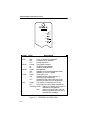
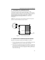
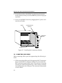
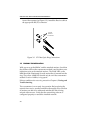
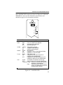
TRFMIM-22, TRFMIM-26,
& TRFMIM-28
TOKEN RING FIBER
MEDIA INTERFACE MODULES
USER’S GUIDE
CABLETRON SYSTEMS, P. O. Box 5005, Rochester, NH 03867-0505
The Complete Networking Solution™
CABLETRON SYSTEMS, P. O. Box 5005, Rochester, NH 03867-0505
NOTICE
NOTICE
Cabletron Systems reserves the right to make changes in
specifications and other information contained in this document
without prior notice. The reader should in all cases consult
Cabletron Systems to determine whether any such changes have
been made.
The hardware, firmware, or software described in this manual is
subject to change without notice.
IN NO EVENT SHALL CABLETRON SYSTEMS BE LIABLE FOR
ANY INCIDENTAL, INDIRECT, SPECIAL, OR
CONSEQUENTIAL DAMAGES WHATSOEVER (INCLUDING
BUT NOT LIMITED TO LOST PROFITS) ARISING OUT OF OR
RELATED TO THIS MANUAL OR THE INFORMATION
CONTAINED IN IT, EVEN IF CABLETRON SYSTEMS HAS BEEN
ADVISED OF, KNOWN, OR SHOULD HAVE KNOWN, THE
POSSIBILITY OF SUCH DAMAGES.
© Copyright July 1993 by:
Cabletron Systems, Inc.
P.O. Box 5005
Rochester, NH 03867-0505
All Rights Reserved
Printed in the United States of America
Order Number: 9030896 July 93
TRFMIM-22, TRFMIM-26, TRFMIM-28, TRMM, and MMAC are
trademarks of Cabletron Systems, Inc.
LANVIEW and Remote LANVIEW are registered trademarks of
Cabletron Systems, Inc.
IBM is a registered trademark of International Business Machines
Corporation.
Printed on
Recycled Paper
i
NOTICE
FCC NOTICE
This device complies with Part 15 of the FCC rules. Operation is
subject to the following two conditions: (1) this device may not
cause harmful interference, and (2) this device must accept any
interference received, including interference that may cause
undesired operation.
NOTE: This equipment has been tested and found to comply with
the limits for a Class A digital device, pursuant to Part 15 of the FCC
rules. These limits are designed to provide reasonable protection
against harmful interference when the equipment is operated in a
commercial environment. This equipment uses, generates, and can
radiate radio frequency energy and if not installed in accordance
with the operator’s manual, may cause harmful interference to
radio communications. Operation of this equipment in a residential
area is likely to cause interference in which case the user will be
required to correct the interference at his own expense.
WARNING: Changes or modifications made to this device which
are not expressly approved by the party responsible for compliance
could void the user’s authority to operate the equipment.
DOC NOTICE
This digital apparatus does not exceed the Class A limits for radio
noise emissions from digital apparatus set out in the Radio
Interference Regulations of the Canadian Department of
Communications.
Le présent appareil numérique n’émet pas de bruits
radioélectriques dépassant les limites applicables aux appareils
numériques de la class A prescrites dans le Règlement sur le
brouillage radioélectrique édicté par le ministère des
Communications du Canada.
ii
TABLE OF CONTENTS
TABLE OF CONTENTS
CHAPTER 1
INTRODUCTION
1.1 Using this Manual........................................................................ 1-1
1.2 The TRFMIM Concentrator Modules........................................ 1-2
1.3 Related Manuals........................................................................... 1-5
1.4 Recommended Reading .............................................................. 1-5
1.5 Getting Help ................................................................................. 1-5
CHAPTER 2 INSTALLATION REQUIREMENTS/
SPECIFICATIONS
2.1 Network Requirements ............................................................... 2-1
2.2 Cable Specifications ..................................................................... 2-1
2.3 Operating Specifications ............................................................. 2-2
2.3.1
2.3.2
2.3.3
2.3.4
Ring Speed .......................................................................... 2-2
Ring Order .......................................................................... 2-3
LANVIEW LEDs................................................................ 2-3
General Specifications....................................................... 2-5
CHAPTER 3
INSTALLING THE CONCENTRATOR MODULE
3.1 Unpacking the Concentrator Module ....................................... 3-2
3.2 Configuring the Concentrator Module ..................................... 3-3
3.3 Installing the Concentrator Module into the MMAC ............. 3-3
3.4 Connecting Lobe Cabling............................................................ 3-4
3.5 Finishing the Installation ............................................................ 3-6
iii
TABLE OF CONTENTS
CHAPTER 4
TESTING AND TROUBLESHOOTING
4.1 Installation Checkout ...................................................................4-1
4.2 Using LANVIEW ..........................................................................4-2
iv
INTRODUCTION
CHAPTER 1
INTRODUCTION
Welcome to the TRFMIM Token Ring Fiber Media Interface
Modules Installation Guide. This manual serves as a reference for
installing and troubleshooting Cabletron Systems TRFMIM-22™,
TRFMIM-26™, and TRFMIM-28™.
The TRFMIM is a fiber optic token ring concentrator module for use
in the Cabletron MMACs. These concentrators are designed in
compliance with the IEEE 802.5J token ring fiber optic standard.
Available with six, twelve or eighteen ports, the TRFMIM provides
connectivity over multimode fiber optic cable.
Note: The term Concentrator Module is used throughout this manual
when describing features and functions that are common to the
TRFMIM-22, TRFMIM-26, and TRFMIM-28. The terms TRFMIM-22,
TRFMIM-26, and TRFMIM-28 are used when it is necessary to describe
features that are unique to any device.
1.1
USING THIS MANUAL
Prior to installing and operating your concentrator module, read
through this manual completely to familiarize yourself with its
contents and to gain an understanding of the features of the
concentrator module.
A general working knowledge of Token Ring (IEEE 802.5) networks
will be helpful when installing your concentrator module.
Chapter 1, Introduction, describes how to use this document,
provides an overview of the features and capabilities of each
concentrator module, and concludes with a list of related manuals.
Chapter 2, Installation Requirements/Specifications, lists the
network requirements that must be met before you begin installing
1-1
INTRODUCTION
your concentrator module. Detailed specifications for each of the
concentrator modules is also provided.
Chapter 3, Installing the Concentrator Module, contains
instructions for installing a concentrator module into the MMAC,
and attaching token ring station cabling.
Chapter 4, Testing and Troubleshooting, describes checks that you
can perform if you encounter problems after installing a
concentrator module. Instructions for using LANVIEW®,
Cabletron Systems built-in visual diagnostic and status monitoring
system, are also included.
1.2
THE TRFMIM CONCENTRATOR MODULES
The TRFMIM-22, TRFMIM-26, and TRFMIM-28, shown in
Figure 1-1, can be installed as a free-standing token ring network or
to provide fiber optic connectivity to an existing token ring
network. The concentrator modules are designed for installation
into a Cabletron Systems MMAC. Since they do not have externally
accessible Ring-In and Ring-Out ports, they are considered
concentrator modules. (A concentrator in token ring applications is
defined as a device with multiple TCU ports bound by externally
accessible Ring-In and Ring-Out ports.)
All concentrator modules are designed for installation into a
Cabletron Systems MMAC, where they can be used to create an
independent 6, 12, or 18 port ring or to expand an existing token
ring network. When any concentrator module is used within an
MMAC, the concentrator module is connected via the Flexible
Network Bus (FNB) to other token ring MIMs, repeaters, or bridges.
1-2
INTRODUCTION
TRFMIM-26
TRFMIM-22
ERR
ERR
MGMT
MGMT
16 MB
FLNK
FLNK
INS
INS
TX
RX
1
FLNK
INS
FLNK
8
INS
2
FLNK
INS
FLNK
9
3
FLNK
INS
FLNK
4
FLNK
INS
16
FLNK
10
FLNK
INS
INS
11
5
RX
4
FLNK
INS
FLNK
INS
17
11
5
RX
FLNK
FLNK
INS
FLNK
FLNK
INS
INS
TX
FLNK
INS
FLNK
INS
TX
12
RX
FLNK
INS
TX
5
6
FLNK
INS
RX
TX
INS
3
TX
10
FLNK
TX
FLNK
INS
9
FLNK
INS
RX
RX
FLNK
INS
15
INS
TX
4
INS
2
RX
FLNK
TX
8
FLNK
INS
RX
TX
FLNK
INS
TX
3
RX
FLNK
INS
14
INS
TX
INS
1
RX
FLNK
RX
INS
7
FLNK
INS
RX
INS
13
TX
2
TX
INS
16 MB
FLNK
RX
TX
RX
Figure 1-1
INS
FLNK
TX
FLNK
INS
MGMT
FLNK
INS
7
RX
TX
ERR
16 MB
FLNK
TX
1
RX
TRFMIM-28
6
18
12
6
RX
The TRFMIM Token Ring Concentrator Modules
1-3
INTRODUCTION
Features of the concentrator module include:
Number of Connections
•
•
•
TRFMIM-22
TRFMIM-26
TRFMIM-28
12 - fiber optic ports
6 - fiber optic ports
18 - fiber optic ports
Multiple concentrator modules can be installed into an MMAC to
increase the number of ports available on a token ring network.
Speed Fault Protection
If a station attempts to insert into the ring at a ring speed (4 or 16
Mb/s) different from what is set on the TRFMIM, that port is
automatically disabled to prevent the ring from beaconing. The
INS LED flashes red indicating the port with the speed fault is
disabled.
Multiple Concentrator Modules
Several concentrator modules can be installed into a single MMAC
and configured as independent rings or linked together into a
single ring network thru the FNB. Configuration guidelines can be
found in Chapter 3, Installing the Concentrator Module.
The TRMM (Token Ring Management Module) is used to manage
the TRFMIM. A variety of network management tools can be used
to control and monitor TRFMIMs (via the TRMM), including
Cabletron Systems Local Management, Remote LANVIEW/
Windows®, and SPECTRUM®.
LANVIEW LEDs
Several LEDs, on the front panel of the concentrator module, are
used to indicate the ring speed, presence of a network error, status,
and management statistics for each of the TCU ports. LANVIEW is
1-4
INTRODUCTION
an effective tool to help you quickly diagnose your physical layer
network problems.
1.3
RELATED MANUALS
The manuals listed below should be used to supplement the
procedures and other technical data provided in this manual. The
procedures in them will be referenced, where appropriate, but will
not be repeated.
Cabletron Systems MultiMedia Access Center Overview and Set
Up Guide
Cabletron Systems Token Ring Local Management for the
Cabletron Systems TRMM
1.4
RECOMMENDED READING
The following publications are recommended if more information
is required on implementing a token ring network.
Local Area Networks, Token Ring Access Method, IEEE Standard
802.5J
Commercial Building Wiring Standard, EIA Standard Proposal
No. 1907-B (if approved, to be published as EIA/TIA-568)
LAN Troubleshooting Handbook, Mark Miller (1989, M&T
Publishing)
1-5
INTRODUCTION
1.5
GETTING HELP
If you need additional support related to the Cabletron Systems
Token Ring products, or if you have any questions, comments or
suggestions related to this manual, contact Cabletron Systems
Technical Support at:
Cabletron Systems, Inc.
P. O. Box 5005
Rochester, NH 03867-0505
Phone: (603) 332-9400
1-6
REQUIREMENTS/SPECIFICATIONS
CHAPTER 2
INSTALLATION
REQUIREMENTS/SPECIFICATIONS
Before you attempt to install your concentrator module, review the
installation requirements and operating specifications that are
outlined in this chapter.
Your network installation must meet the conditions, guidelines,
specifications, and requirements included in this chapter to obtain
satisfactory performance from this equipment. Failure to follow
these guidelines could produce poor network performance.
2.1
NETWORK REQUIREMENTS
Take care in planning and preparing the cabling and connections
for your network. The quality of the connections, the length of
cables and other conditions of the installation are critical factors in
determining the reliability of your network. Work area wall plates/
outlets used for your token ring network should be clearly labeled
as token ring network lobe connections.
The following sections describe network requirements for this
equipment.
2.2
CABLE SPECIFICATIONS
When connecting a Fiber Optic Link Segment to TRFMIM, the
following network requirements must be met:
•
Cable Type - The cable must be one of the following multimode
fiber optic media:
-
50/125 µm fiber optic cabling.
62.5/125 µm fiber optic cabling.
100/140 µm fiber optic cabling.
2-1
REQUIREMENTS/SPECIFICATIONS
•
Attenuation - The fiber optic cable must be tested with a fiber
optic attenuation test set that is adjusted for an 850 nm
wavelength. This test verifies that the signal loss in a cable is
within an acceptable level:
-
13.0 dB or less for 50/125 fiber cable segment.
16.0 dB or less for 62.5/125 fiber cable segment.
19.0 dB or less for 100/140 fiber cable segment.
•
Budget and Propagation Delay - When determining the
maximum fiber optic cable length, the fiber optic budget delay
and total network propagation should be calculated and taken
into consideration before fiber optic cable runs are incorporated
in any network design. Fiber optic budget is the combination of
the optical loss due to the fiber optic cable, in-line splices, and
fiber optic connectors. Propagation delay is the amount of time
it takes a packet to travel from the sending device to the
receiving device.
•
Length - The maximum allowable fiber optic cable length is
2 km.
2.3
OPERATING SPECIFICATIONS
This section describes the operating specifications for each of the
fiber optic token ring concentrator modules. Cabletron Systems
reserves the right to change these specifications at any time without
notice.
2.3.1
Ring Speed
The concentrator module ring speed can be set to default to either 4
Mbit/s or 16 Mbit/s. The ring speed is automatically set to a default
setting at power on. The default ring speed can be selected by
positioning a network speed jumper on the board (Refer to Chapter
3, Installing the Concentrator Module, to learn how to set the
network speed jumper.) The default setting can be overridden by
changing the ring speed through local or remote network
management software.
2-2
REQUIREMENTS/SPECIFICATIONS
2.3.2
Ring Order
When multiple Token Ring boards (set to the same ring speed) are
installed in adjacent slots within an MMAC, they can be attached
via the FNB to create a larger ring network. Multiple Token Ring
boards are automatically attached (when possible) at power on, but
the configuration can be modified via network management
software, attaching or detaching adjacent boards and, as a result
creating separate rings, changing the ring sequence.
In a network using a concentrator module attached to other Token
Ring boards via the FNB, the ring order is in MMAC slot number
order, and then port number order within each Token Ring board.
Example: TRFMIM-22 in slot 1 with ports 2, 5, 8, & 12 in use.
TRFMIM-22 in slot 2 with ports 1, 5, 7, 11, & 12 in use.
An FNB is installed in the MMAC.
Ring order for this example is Slot 1 ports 2, 5, 8, 12, out to the FNB,
then to Slot 2 ports 1, 5, 7, 11, 12 out to the FNB; then, returning to
Slot 1 ports 2, 5, etc.
2.3.3
LANVIEW LEDs
There are a number of LEDs on the front panel of the concentrator
modules. While the quantity of port-specific LEDs differ between
the 6, 12 and 18 port concentrator modules, all concentrator
modules are equipped with the same indicators. These are
illustrated in Figure 2-1.
2-3
REQUIREMENTS/SPECIFICATIONS
TRFMIM-26
ERR
MGMT
16 MB
FLNK
INS
TX
1
RX
Label
ERR
16 Mb
MGMT
FLNK
INS
Color
Red
ON
OFF
Yellow
on
off
Green
ON
OFF
Green
ON
Error or Speed Fault detected
Hardware error detected
Normal operation
Ring Speed Indicator
16 Mbit/s mode selected
4 Mbit/s mode selected
Management
Repeater is set for Management Mode
Repeater is in AUTO Mode
Fiber Optic Link
Respective Fiber Optic lobe port is
receiving (link established)
OFF
Respective Fiber Optic lobe port is not
receiving a signal (no link established)
Green
The station is inserted into the ring.
OFF
Ring insertion has not been established
Flashing Green - Station is inserted, but the port is
disabled by management
Red Station trying to insert is at the
wrong ring speed and this port is
automatically disabled
Figure 2-1
2-4
Description
TRFMIM LANVIEW LEDs
REQUIREMENTS/SPECIFICATIONS
2.3.4
General Specifications
SAFETY
Warning: It is the responsibility of the person who sells the system to
which the TRFMIM will be a part to ensure that the total system meets
allowed limits of conducted and radiated emissions.
This equipment is designed in accordance with UL478, UL910, NEC
725-2(b), CSA, IEC, TUV, VDE Class A, and meets FCC Part 15,
Class A limits.
PHYSICAL
Dimensions
(includes front panel)
13.4D x 11.5H x 2.0W inches
(34.0D x 29.2H x 5.1W centimeters)
Weight
2 lbs. 2 oz.
(963.9 grams)
2-5
INSTALLING THE CONCENTRATOR MODULE
CHAPTER 3
INSTALLING THE
CONCENTRATOR MODULE
This chapter contains instructions for installing your concentrator
module into a Cabletron Systems MMAC product and connecting
token ring stations at the concentrator module’s trunk coupling
unit (TCU) ports.
Check that all requirements listed in Chapter 2, Installation
Requirements/ Specifications, have been met before installing and
operating the concentrator module. When you install your
concentrator module, the following guidelines will help you to
properly configure your system:
•
The concentrator module cannot be installed into the rightmost
slot. This slot is reserved for specific management/bridging/
repeater modules.
•
When the concentrator module is being installed into an
MMAC-8, be sure that a PSM or PSM-R is installed in the
associated rear power supply slot. The PSM or PSM-R, Power
Supply Module is the source of power for MMAC modules.
One Power Supply Module is required for every two MIMs.
Note: The PSM-R (Redundant Power Supply Module) is recommended
for use with the MMAC-8FNB (with a Flexible Network Bus).
•
Multiple token ring products, within an MMAC, are
automatically linked at power on, provided that the following
conditions are met:
- The MMAC must be configured with an FNB, (either an
MMAC-3FNB, MMAC-5FNB, MMAC-8FNB or an
MMAC-M8FNB). Without the FNB, the individual MIMs
will not be linked, but will form independent Token Ring
networks.
3-1
INSTALLING THE CONCENTRATOR MODULE
NOTE: The FNB is a full-height, full-width backplane that links
Cabletron Systems Token Ring products. MMAC-3s and MMAC-8s
(without an FNB) can be upgraded with an FNB, providing greater
flexibility in configuring your system. Contact Cabletron Systems
Technical Support for more information.
- The boards being linked must be arranged sequentially in
adjacent MMAC slots, e.g., slots 2, 3, and 4.
- To link Token Ring boards, the boards must be set to the
same ring speed. Token Ring boards operating at different
ring speeds (4 Mbit/s and 16 Mbit/s) cannot be attached to
the same ring network. Linking boards set to different ring
speeds requires the use of a bridging device.
•
3.1
To establish a network path between a token ring network and
another network type (i.e., FDDI or Ethernet) requires the use of
a bridging device.
UNPACKING THE CONCENTRATOR MODULE
Prior to installation, unpack and visually inspect your concentrator
module for damage.
CAUTION: Electrostatic Discharge (ESD) can damage your
concentrator module. Observe all precautions to prevent electrostatic
discharges when handling the concentrator module. Hold only the edges of
the board or the metal front panel. Avoid touching the components or
surface of the board.
1. Carefully remove the concentrator module from the shipping
box. Save the box and materials for possible future repackaging
and shipment.
2. Remove the concentrator module from its protective plastic bag
and set it on top of its protective bag in a static free area. This
will help to prevent ESD damage.
Contact Cabletron Systems Technical Support immediately if you
encounter any problems unpacking or installing your concentrator.
3-2
INSTALLING THE CONCENTRATOR MODULE
3.2
CONFIGURING THE CONCENTRATOR MODULE
Position the hardware jumper on the proper pins on the
concentrator module to select either 4 or 16 Mbit/s as the default
network ring speed (see Figure 3-1). The speed setting is a factor in
determining the maximum lobe length. Refer to Chapter 2,
Installation Requirements/Specifications for additional
information.
NOTE: The network speed is also selectable by software. The software
selection overrides the hardware jumper selection.
4 Mbit/sec
16 Mbit/sec
...
Mother board
Daughter board
Front
Panel
Figure 3-1
3.3
Network Speed Jumper
INSTALLING THE CONCENTRATOR MODULE INTO THE MMAC
Install the concentrator module into the MMAC as follows:
1. If it is not already powered off, power off the MMAC chassis by
unplugging the AC power cord from the wall outlet.
2. Remove the selected blank panel from the MMAC and slide the
concentrator module into the MMAC card cage (see Figure 3-2).
Be sure that the card is in the card guides at the top and bottom
slots of the card cage.
3-3
INSTALLING THE CONCENTRATOR MODULE
3. Secure the module to the MMAC by tightening the knurled
knobs. Failure to firmly secure the MIM may result in improper
operation.
4. Power on the MMAC chassis by plugging the AC power cord
into the wall outlet.
MMAC
CONCENTRATOR
MODULE
TRMM
TRFMIM-22
ERR
MGMT
FLNK
INS
TX
16 MB
FLNK
KNURLED
KNOBS
INS
7
1
RX
FLNK
INS
TX
FLNK
INS
8
2
RX
FLNK
INS
TX
RX
INS
FLNK
INS
9
FLNK
3
INS
FLNK
TX
10
4
RX
FLNK
INS
TX
FLNK
INS
11
5
RX
FLNK
INS
TX
FLNK
INS
12
6
RX
BOARD SLOT
Figure 3-2
3.4
Installing the Concentrator Module
CONNECTING LOBE CABLING
When connecting a fiber optic link segment keep the following in
mind:
•
3-4
When connecting a fiber optic link segment with ST connectors,
keep in mind that ST connectors attach to ST ports much like
BNC connectors attach to BNC ports. The connector is inserted
into the port with the alignment key on the connector inserted
into the alignment slot on the port. The connector is then turned
to lock it down.
INSTALLING THE CONCENTRATOR MODULE
•
The physical communication link consists of two strands of
fiber optic cabling: the Transmit (TX) and the Receive (RX). The
Transmit strand from the applicable port on the module will be
connected to the Receive port of a fiber optic device at the other
end of the segment. For example, TX of the applicable port on
the module will go to RX of the other fiber optic device. The
Receive strand of the applicable port on the module will be
connected to the Transmit port of the fiber optic device. For
example, RX of the applicable port on the module will go to TX
of the other fiber optic device.
It is recommended that you label the fiber optic cable to indicate
which fiber is Receive and which is Transmit. When you buy
fiber optic cable from Cabletron Systems, it is labeled so that: at
one end of the cable, one fiber is labeled 1, and the other fiber is
labeled 2. This pattern is repeated at the other end of the cable.
If you did not purchase your cable from Cabletron Systems, be
sure you have labeled your cable in the manner described
above.
Caution: Do not touch the ends of the fiber optic strands, and do not let
the ends come in contact with dust, dirt, or other contaminants.
Contamination of the ends can cause problems in data transmissions.
If the ends become contaminated, clean them with alcohol using a soft,
clean, lint free cloth.
Install the fiber optic ring cables as follows:
Caution: Fiber optic cables must be handled with care. Avoid twisting or
bending the cable sharply. Do not touch the end of an exposed optic fiber.
1. Locate the fiber optic cable.
2. If the cables are not labeled or color coded, determine the
function for each cable and label them now.
3. Remove the protective covers from the ST connections.
4. Attach the fiber optic cables according to labeling. Attach the
Transmit cable to the appropriate TX (ST) connection at the
3-5
INSTALLING THE CONCENTRATOR MODULE
front of the repeater (see Figure 3-3). Attach the Receive cable at
the appropriate RX (ST) connector.
ST Fiber
OpticPort
TX
ST Connector
RX
Figure 3-3
3.5
ST Fiber Optic Ring Connections
FINISHING THE INSTALLATION
With power on at the MMAC and the attached stations, check that
the red Error LED on the concentrator module is not lit and no error
indications exist at the attached stations. The FLNK LED on the
MIM should be illuminated for each station that is inserted into the
ring. The yellow 16MB LED should only be on if the concentrator
module is set for 16 Mbit/s ring speed.
If these conditions do not exist, proceed to Chapter 4, Testing and
Troubleshooting.
The concentrator is now ready for operation. Before placing the
network into service, test the installation thoroughly to be sure that
all stations are able to be addressed and that the data is being
relayed without error. Verify that the networking software is
configured properly to match the installed network.
3-6
TESTING AND TROUBLESHOOTING
CHAPTER 4
TESTING AND TROUBLESHOOTING
This section contains procedures to verify that the connections
between the concentrator module and the token ring stations are
functioning properly. A description of the LANVIEW LEDs is also
provided.
4.1
INSTALLATION CHECKOUT
Perform the following to check the installation of the concentrator
module:
1. Be sure that the token ring stations and the MMAC match the
AC power source (120 Vac or 240 Vac) and are powered on.
2. Trace the ring path through the network, to be sure that there
are no breaks in the ring and that it is free from logical design
errors. While tracing the ring:
a. Check each cable connection at the MIM.
b. Verify the pinouts for every connection.
c. Check the cable conductors for continuity. Cable testers are
available for this task.
d. Check that cable connections at patch panels and wall plates
are secure.
5. Check the network ring speed:
a. Verify that the ring speed matches the station and cable
specifications mentioned in Chapter 2, Installation
Requirements/Specifications.
4-1
TESTING AND TROUBLESHOOTING
b. Be sure that all devices in the ring network are set to the
same ring speed. Check all MIMs and stations in the
network.
c. Check that the MIMs in the MMAC are grouped together
according to network type and data rate. For example,
Ethernet MIMs together, 4 Mbit/s token ring MIMs
together, and 16 Mbit/s token ring MIMs together.
4. Ensure that the maximum cable length for EACH station and
the maximum number of stations are not exceeded.
When these checks have been successfully completed for each
connection, the concentrator module is ready for normal operation.
If further problems occur, contact Cabletron Systems Technical
Support.
4.2
USING LANVIEW
LANVIEW is Cabletron Systems built-in visual diagnostic and
status monitoring system. Using LANVIEW, your network
troubleshooting personnel can quickly scan the LANVIEW LEDs to
determine network status, diagnose network problems, and isolate
faulty nodes or trunk segments.
4-2
TESTING AND TROUBLESHOOTING
The LANVIEW LED locations are shown in Figure 4-1. While the
TRFMIM-26 is shown in the illustration, the locations and
definitions apply to all concentrator modules.
TRFMIM-26
ERR
MGMT
16 MB
FLNK
INS
TX
1
RX
Label
ERR
16 Mb
MGMT
FLNK
INS
Color
Description
Red
ON
OFF
Yellow
on
off
Green
ON
OFF
Green
ON
Error or Speed Fault detected
Hardware error detected
Normal operation
Ring Speed Indicator
16 Mbit/s mode selected
4 Mbit/s mode selected
Management
Repeater is set for Management Mode
Repeater is in AUTO Mode
Fiber Optic Link
Respective Fiber Optic lobe port is
receiving (link established)
OFF
Respective Fiber Optic lobe port is not
receiving a signal (no link established)
Green
The station is inserted into the ring.
OFF
Ring insertion has not been established
Flashing Green - Station is inserted, but the port is
disabled by management
Red Station trying to insert is at the
wrong ring speed and this port is
automatically disabled
Figure 4-1
LANVIEW LEDs
4-3