1
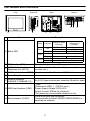
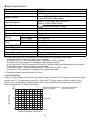
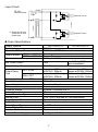
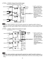
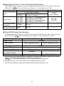
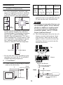
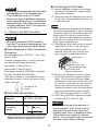
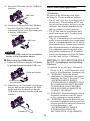
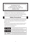
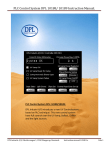
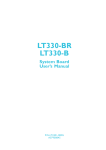
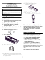
(9) USB Cable Clamp (1 set) (Holder: 1, Cover: 1) LT-3300 Series Installation Guide Caution Be sure to read the “Warning/Caution Information” on the attached sheet before using the product. (10) EX module *1 Hook (only for LT-3300 Series) (1) Package Contents (1) LT Unit (1) (2) English and Japanese Installation Guides (one of each) <This Guide> (3) Warning/Caution Information (1) (4) English and Japanese EX Module Hardware Manual *1 (1) (5) Installation Gasket (1, attached to the LT unit) (6) Installation Fasteners (Set of 4) This unit has been carefully packed, with special attention to quality. However, should you find anything damaged or missing, please contact your local LT distributor immediately. About the Manual (7) DIO Connector (1) For the detailed information on LT3000 series, refer to the following manual. • LT3000 Series Hardware Manual • Maintenance/Troubleshooting • GP-Pro EX Reference Manual “Controlling External I/O” • Device/PLC Connection Manual LT3000 Series Hardware Manual can be selected from the help menu of GP-Pro EX or downloaded from Pro-face Home Page. URL http://www.pro-face.com/otasuke/ (8) Power Connector (1) *1 The EX module is an extension I/O unit for the LT 3000 series. To use the EX module, be sure to read the supplied manual. 1 Part Names and Functions Right side Front Rear Bottom E F G B A C D Name Orange B DIO Interface (DIO) AUX Unit Interface/ Expansion Unit (EXT2) Indicator ON Green Red C E Description Color A Status LED H Flashing ON Flashing ON Flashing Operation Mode (Drawing) Logic execution mode (when logic is enabled) OFFLINE — In operation RUN In operation STOP When power is turned on. In operation Major Error Backlight burnout During software startup The interface to external I/O equipment Used to connect additional units (communication function, etc.). D EX Module Interface (EXT1) Used to connect the Pro-face's EX Module E Power Plug Connector — Ethernet Interface F (10BASE-T/100BASE-TX) An RJ-45 type modular jack connector (8-pole) is used. G USB Host Interface (USB) 1 port Conforms to USB1.1. (TYPE-A conn.) Power Supply Voltage: DC5V ±5% Output Current: 500mA (at maximum) The maximum communication distance is 5m. H Serial Interface (COM1) D-sub 9-pin plug type connector. Communication method (RS232C/RS422/RS485) is switched via software. 2 General Specifications Power Supply Electrical Specifications Input Voltage DC24V Rated Voltage DC19.2 to 28.8V Allowable Voltage Drop 3ms (max.) Power Consumption 27W (max.) In-Rush Current 30A (max.) Voltage Endurance AC1000V 20mA for 1minute (between charging and FG terminals) Insulation Resistance DC500V 10MΩ (min.) (between charging and FG terminals) Physical Environmental Specifications Surrounding Operating Temperature 0 to +50°C*1 Storage Temperature -20 to +60°C Ambient Humidity 10 to 90% RH (Wet bulb temperature: 39°C max. - no condensation.) Storage Humidity 10 to 90% RH (Wet bulb temperature: 39°C max. - no condensation.) Dust 0.1mg/m3 and below (non-conductive levels) Pollution Degree For use in Pollution Degree 2 environment *1 When using in an environment where the temperature becomes or exceeds 40°C for an extended period of time, the screen contrast level may decrease from its original level of brightness. 3 External Interfaces • For instructions on how to connect to other devices, always refer to the “GP-Pro EX Device/PLC Connection Manual”. • Always connect the #5 SG (Signal Ground) of the LT unit to the connected device, especially if the connected device is also not isolated. Failure to do so may damage the RS232C/RS422/RS485 circuit. • When isolation is necessary, you can use the RS232C isolation unit (CA3-ISO232-01) on COM1. COM1 Recommended Cable Connector XM2D-0901 <made by OMRON Corp.> Recommended Jack Screw XM2Z-0073 <made by OMRON Corp.> Recommended Cable Cover XM2S-0913 <made by OMRON Corp.> Interfit Bracket #4-40 UNC screws are used. Pin # RS232C Signal Name RS422/RS485 Meaning Signal Name Meaning 1 CD Carrier Detect RDA Receive Data A(+) 2 RD(RXD) Receive Data RDB Receive Data B(-) 3 SD(TXD) Send Data SDA Send Data A(+) 4 ER(DTR) Data Terminal Ready ERA Data Terminal Ready A(+) 5 SG Signal Ground SG Signal Ground 6 DR(DSR) Data Set Ready CSB Clear to Send B(-) 7 RS(RTS) Request to Send SDB Send Data B(-) 8 CS(CTS) Clear to Send CSA Clear to Send A(+) 9 CI(RI)/VCC Called status display/ ERB +5V±5% Output 0.25A*1 Data Terminal Ready B(-) FG Frame Ground (Common with SG) Frame Ground (Common with SG) Shell FG *1 The RI/VCC selection for Pin #9 is switched via software. The VCC output is not protected against overcurrent. To prevent damage or unit malfunctions, use only the rated current. 4 DIO Interface (Connector) • When preparing the cable to connect the wiring, check the pin numbers inscribed on the DIO Connector. 2-1871940-9 <Tyco Electronics AMP.> CA7-DIOCN5-01 <Pro-face> Applicable connector Pin Arrangement A1 B1 Pin No. A1 A2 A3 A4 A5 A6 A7 A8 A9 A10 A11 A12 A13 A19 B19 (Cable connection side) A14 A15 A16 A17 A18 A19 Signal Name IN1 IN3 IN5 IN7 IN9 IN11 IN13 IN15 NC Sink: NC Source: +24V Sink: 0V Source: NC OUT1 (PLS1, PWM1) OUT3 (PLS3, PWM3) OUT5 OUT7 OUT9 OUT11 OUT13 OUT15 Pin No. B1 B2 B3 B4 B5 B6 B7 B8 B9 B10 B11 B12 B13 B14 B15 B16 B17 B18 B19 Signal Name IN0 (CT0) IN2 (CT1) IN4 (CT2) IN6 (CT3) IN8 IN10 IN12 IN14 COM Sink: +24V Source: +24V Sink: 0V Source: 0V OUT0 (PLS0, PWM0) OUT2 (PLS2, PWM2) OUT4 OUT6 OUT8 OUT10 OUT12 OUT14 • Parenthesized signal names ( ) indicate when Pulse output (PLS∗), PWM output (PWM∗), or Counter Input (CT∗) are used. 5 Input Specifications Rated Voltage Maximum Allowable Voltage Input Method Rated Current Input Resistance Input Derating Input Points Common Lines Common Design ON Voltage Operation Range OFF Voltage Input Delay OFF to ON *1 Time ON to OFF Input Signal Display Status Display Isolation Method External Connection External Power Supply DC24V DC28.8V Sink/Source Input 6.5mA (DC24V) (IN0, IN2, IN4, IN6) 4.1mA (DC24V) (Other input) Approx. 3.7kΩ (IN0, IN2, IN4, IN6) Approx. 5.9kΩ (Other input) SEE •Input Derating (6 page) 16 1 16 points/1 common line DC19V or more DC5V or less 0.5 to 20ms*2 0.5 to 20ms*2 No LED indicators None Photocoupler Isolation 38-pin connector (used with Output section) For Signal: DC 24V *1 In the case of IN0, IN2, IN4, and IN6, the input delay time generates a 5µs delay. For example, in the case of a 0.5ms-cycle sampling: 5µs (ON to OFF) + 0.5ms (sampling cycle) + 5µs (OFF to ON) = 0.51ms A minimum 0.51ms-restriction is imposed on the input pulse width. In the case of IN1, IN3, IN5, and from IN7 to IN15, the input delay time generates a 0.5ms-delay. For example, in the case of a 0.5ms-cycle sampling: 0.5ms (ON to OFF) + 0.5ms (sampling cycle) + 0.5ms (OFF to ON) = 1.5ms A minimum 1.5ms-restriction is imposed on the input-pulse width. *2 Digital filter can be set at intervals of 0.5 ms. • Input Derating Using LT input voltage that exceeds the rated voltage, the input ON voltage, the number of input points or the LT’s temperature can effect. Also, the LT's input section could overheat, which could lead to an accident or malfunction. Refer to the following drawing and perform Input Derating within the LT unit’s rated range. Input ON Rate (%) 100 For horizontal mounting DC24.0 to 26.4V DC28.8V 50 0 0 10 20 30 40 50 (°C) Ambient Operating Temperature 6 For vertical mounting DC24.0 to 25.2V • Input Circuit DC 24V External Power + - + COM B9 *1 Internal Circuit IN15 A8 *1 Dotted line shows connection to sink output type. IN14 IN13 IN12 IN11 IN10 IN9 IN8 IN7 IN6 IN5 IN4 IN3 IN2 IN1 IN0 B8 A7 B7 A6 B6 A5 B5 A4 B4 A3 B3 A2 B2 A1 B1 Internal Circuit Output Specifications Output Terminal Rated Voltage Allowable Voltage Range LT330∗-∗1-D24-K Output Method LT330∗-∗1-D24-C Maximum Load Voltage Min. Load Current Output Voltage Drop Output Delay Time OFF to ON ON to OFF Voltage Leakage (when OFF) Clamp Voltage Type of Output Common Lines Common Design External Connection Output Protection Type Internal Fuse Surge Control Circuit Output Points Output Signal Display Status Display Element Isolation Method External Power Supply OUT0 to OUT3 OUT4 to OUT15 DC24V DC20.4V to DC28.8V Sink Output Source Output 0.2A /point, 1.6A /common 1mA (Pulse/PWM out1mA put unavailable) DC0.5V or less 5µs or less (With output 0.5ms or less (With at DC24V, 200mA) output at DC24V, 200mA) 5µs or less (With output 0.5ms or less (With at DC24V, 200mA) output at DC24V, 200mA) 0.1mA or less 39V ± 1V Transistor Output 2 8 points/1 common line x2 38-pin connector (also used for Input) Output is unprotected 3.5A, 125V Chip fuse x2 (not replaceable) Zener diode 16 No LED indicators None Photocoupler Isolation For Signal: DC 24V 7 • LT330∗-∗1-D24-K Output Circuit (Sink type) +24V B10 Internal Circuit Fuse 3.5A - + 0V B11 OUT7 A15 L OUT6 OUT5 OUT4 OUT3 OUT2 OUT1 OUT0 Internal Circuit B15 A14 B14 A13 B13 A12 B12 L Internal Circuit Fuse 3.5A 0V A11 Internal Circuit OUT15 OUT14 OUT13 OUT12 OUT11 OUT10 OUT9 L A19 B19 A18 B18 A17 B17 A16 OUT8 B16 *1 OUT0 to OUT3 only (Example) The output delay time (OFF to ON) is 1.5µs where the output current is DC 24V, 50mA. Install an external dummy resistor to increase OUT0 to OUT3 only the amount of current *1 Dummy Resistor when more responsiveness is required and the load is light. DC 24V External Power L • Since the output terminals are not electrically protected, an output line might be short-circuited or a connection fault might burn the external devices and LT. Be sure to install an applicable fuse for each output terminal if there should be the risk for the current running over the rating. • LT330∗-∗1-D24-C Output Circuit (Source type) Fuse 3.5A +24V B10 OUT7 A15 Internal Circuit L OUT6 OUT5 OUT4 OUT3 OUT2 OUT1 OUT0 Internal Circuit B15 A14 B14 A13 B13 A12 B12 L Fuse 3.5A +24V A10 Internal Circuit Internal Circuit OUT15 OUT14 OUT13 OUT12 OUT11 OUT10 OUT9 A19 L B19 A18 B18 A17 B17 A16 + - DC 24V External Power *1 OUT0 to OUT3 only (Example) The output delay time (ON to OFF) is 1.5µs where the output current is DC 24V, 50mA. Install OUT0 to OUT3 only an external dummy Dummy Resistor*1 resistor to increase the amount of current when more responsiveness is required and the load is light. OUT8 B16 L 0V B11 • Since the output terminals are not electrically protected, an output line might be short-circuited or a connection fault might burn the external devices and LT. Be sure to install an applicable fuse for each output terminal if there should be the risk for the current running over the rating. 8 High-Speed Counter / Pulse Catch Input Specifications DIO Standard Input/Output is used as a High-Speed Counter Input. The setup is done by the GP-Pro EX. SEE GP-Pro EX Reference Manual “Controlling External I/O” Input Input Points Counter DC24V Open Collector Single Phase 2 Phase (4 points) (1 point or 2 points) CT0 (IN0), CT0 (IN0), CT1 (IN2) (used as pair) CT1 (IN2), CT0: A Phase, CT1: B Phase CT2 (IN4), CT2 (IN4), CT3 (IN6) (used as pair) CT3 (IN6) CT2: A Phase, CT3: B Phase High Speed Count 100Kpps Frequency Marker Input None (Counter Value Clear) Pulse Catch DC24V Open Collector IN0, IN2, IN4, IN6 50Kpps ⎯ IN3, IN7 ⎯ Pulse/PWM Output Specifications DIO Standard Input/Output is used as a Pulse Output or PWM Output. The setup is done by the GP-Pro EX. SEE GP-Pro EX Reference Manual “Controlling External I/O” Pulse Output Output Points Output Method Load Voltage Min. Load Current Max. Output Frequency Pulse Acceleration/ Deceleration Speed ON Duty PWM Output 4 Points PLS0 to PLS3 (OUT0 to PWM0 to PWM3 (OUT0 to OUT3) defined by user OUT3) defined by user DC24V 1mA Up to 65kHz possible per point (set through software)*1 ⎯ Available 50% ± 10% (at 65kHz)*2 19 to 81% (at 65kHz)*3 *1 A limit of maximum output frequency is imposed on the pulse outputs with regard to the number of channels used and with high-speed counter to be used together. SEE GP-Pro EX Reference Manual "Controlling External I/O" Restrictions *2 The ON Duty error (10%) will be reduced if the Output frequency is low. *3 The ON Duty (effective range) will be widened if the Output frequency is low. 9 Installations 1. LT Installation Requirements +1 LT156.0 -0 3300 +0.04 Series [6.14 ] -0 • For easier maintenance, operation, and improved ventilation, be sure to install the LT at least 100 mm [3.94 in.] away from adjacent structures and other equipment. 100 [3.94] 1.6[0.06] to 5.0[0.20] • It is strongly recommended that you use the installation gasket, since it absorbs vibration in addition to repelling water. For the procedure for replacing the installation gasket, refer to “LT3000 Series Hardware Manual”. (3) The following figures show the four (4) fastener insertion slot locations. Insert each fastener’s hook into the slot and tighten it with a screwdriver. Insert the installation fasteners securely into the insertion slot recess. 100 [3.94] Unit: mm[in.] +1 123.5 -0 +0.04 [4.86 ] -0 100 [3.94] 100 [3.94] 100 [3.94] Panel thickness Y (2) Confirm that the installation gasket is attached to the LT unit and then place the LT unit into the Panel from the front. 100 [3.94] 100 [3.94] X • Be sure that the surrounding air temperature and the ambient humidity are within their designated ranges. (Surrounding air temperature: 0 to 50°C, Ambient humidity: 10 to 90%RH, Wet bulb temperature: 39°C max.) When installing the LT on the panel of a cabinet or enclosure, “Surrounding air temperature” indicates both the panel face and cabinet or enclosure’s internal temperature. Top Inside Cabinet Panel Face Insertion Slots • Be sure that heat from surrounding equipment does not cause the LT to exceed its standard operating temperature. 2. Bottom LT Installation (1) Create a Panel Cut following the dimensions in the table below. X Insertion Slot Recess Hook the fastener on the Recess, Panel r≤3[0.12] thickness Installation Fastener Y Panel LT LT Unit: mm [in.] 10 Hook and secure the fastener on the panel with a screw. Connecting the DIO Cable (1) Insert a flatShead screwdriver, at an angle, into the tool insertion hole (square-shaped hole) of the connector. (2) When inserting the flathead screw driver, be sure that it is perpendicular to the center division wall. • Tightening the screws with too much force can damage the LT unit’s plastic case. • The necessary torque is 0.5N•m. • Be sure to insert installation fasteners in the recessed portion of a installation fasteners hole. If the fasteners are not correctly attached, the LT unit may shift or fall out of the panel. 3. • Make the insertion distance of the flathead screwdriver approximately 4 mm. Inserting forcefully may break the inside of the connector and will a cause of contact defect. Also, do not turn the flathead screwdriver while the tip is inside of the tool insertion hole (square-shaped hole). (3) The adjacent wire insertion hole (roundshaped hole) will be in an open state. With the flathead screwdriver still inserted, insert the wire into the wire insertion hole (round-shaped hole). Wiring to the DIO Connector • Be sure to remove the DIO Connector from the LT unit prior to starting wiring. Failure to do so may cause an electric shock. Items Required to Wire Connectors Screwdriver Recommended type: 1891348-1 <Tyco Electronics AMP.> If another manufacturer is used, be sure the part has the following dimensions: point depth: 1.5mm [0.06in.] point width: 2.4mm [0.09in.] Point shape should be DIN5264A, and meet Security Standard DN EN60900. Also, the screwdriver’s tip should be flat as indicated in order to access the narrow hole of the connector: Screwdriver Wire Wire insertion hole (Round-shaped hole) Tool insertion hole (Square-shaped hole) (4) Remove the flathead screwdriver from the tool insertion hole (square-shaped hole). The wire insertion hole (roundshaped hole) will close and the wire will be secured. In the case of wire removal, remove the desired wire by inserting a flathead screwdriver into the corresponding tool insertion hole (square-shaped hole) following procedures (1) and (2). (5) Insert the wired DIO connector straight into the DIO I/F of the LT unit. Screwdriver Tip Shape DIO Cable Specifications DIO Cable Diameter Conductor Type Conductor Length AWG24 to 18 UL1015 or UL1007 Stranded Wire*1 • Be sure to strip only the amount of cover required. If too much cover is removed, the end wires may short against each other, or against an electrode, which can create an electric shock. If not enough cover is removed the wire cannot carry a charge. 7 mm [0.28in] *1 If the Conductor’s end (individual) wires are not twisted correctly, the end wires may either short against each other, or against an electrode. 11 Power Connector (Plug) Specifications • Do not solder the wire itself. This could lead to a bad or poor contact. • Insert each wire completely into its opening. Failure to do so can lead to a unit malfunction or short, either against wire filaments, or against an electrode. • When wiring, be aware of the installation position, direction, and twisting of the wiring as to not develop stress on the connector. Fix the cable near the LT by cable clamp and set it loosely as to not place tension on the connector. Insertion Direction + − FG y To avoid an electric shock, prior to connecting the LT unit’s power cord terminals to the power terminal block, confirm that the LT unit’s power supply is completely turned OFF, via a breaker, or similar unit. y Any other power level can damage both the LT and the power supply. y Since there is no power switch on the LT unit, be sure to attach a breaker switch to its power cord. y When the FG terminal is connected, be sure the wire is grounded. - 0V Grounding Terminal FG connected to the LT chassis Recommended SZF 1-0.6x3.5 Driver (1204517) AI 0.75-8GY (3200519) Recommended AI 1-8RD (3200030) Pin Terminals AI 1.5-8BK (3200043) AI 2.5-8BU (3200522) Recommended CRIMPFOX ZA 3 Pin Terminal (1201882) Crimp Tool Connecting the LT Power Cord (1) Confirm that the LT unit’s Power Cord is unplugged from the power supply. (2) Strip the power cord, twist the conductor’s wire ends, insert them into the pin terminal and crimp the terminal. Attach the terminal to the power connector (plug). Wiring the DC type power supply cable Power Cord Specifications Use copper conductors only. Power Cord 0.75 to 2.5mm2 (18 - 12 AWG) Diameter Conductor Simple or Stranded Wire*1 Type Conductor Length 24V • The power connector (plug) is CA5-DCCNM01 made by Pro-face or MSTB2,5/3-ST-5,08 made by Phoenix Contact. When connecting the Power Cord, use the following items when performing wiring. (Items are made by Phoenix Contact.) Wiring 1. + • Use a flat-blade screwdriver (Size 0.6 x 3.5) to tighten the terminal screws. The torque required to tighten these screws is 0.5 to 0.6 N•m [5-7Lb•In.]. • Do not solder the cable connection. Doing so may damage the unit due to abnormal heat or cause a fire. 7 mm [0.28in] *1 If the Conductor’s end (individual) wires are not twisted correctly, the end wires may either short against each other, or against an electrode. 12 (3) Attach the Power connector (Plug) to the Power Connector. - + • Be sure to ground the surge absorber (E1) separately from the LT unit (E2). Select a surge absorber that has a maximum circuit voltage greater than that of the peak voltage of the power supply. Power Connector (Socket) FG LT FG E1 Power Connector (Plug) 2. E2 Lightening Surge Absorber 3. Power Supply Cautions Grounding Cautions • Be sure to create an exclusive ground for the Power Cord’s FG terminal. Use a grounding resistance of 100Ω, a wire of 2mm2 or thicker, or your country’s applicable standard. • The SG (signal ground) and FG (frame ground) terminals are connected internally in the LT unit. When connecting the SG line to another device, be sure that the design of the system/connection does not produce a shorting loop. • The grounding wire should have a cross sectional area greater than 2mm2. Create the connection point as close to the LT unit as possible, and make the wire as short, as possible. When using a long grounding wire, replace the thin wire with a thicker wire, and place it in a duct. • Input and Output signal lines must be separated from the power control cables for operational circuits. • To improve the noise resistance, be sure to twist the ends of the power cord wires before connecting them to the Power connector (Plug). • The LT unit’s power supply cord should not be bundled with or kept close to main circuit lines (high voltage, high current), or input/output signal lines. • To reduce noise, make the power cord as short as possible. • If the supplied voltage exceeds the LT unit’s range, connect a voltage transformer. • Between the line and the ground, be sure to use a low noise power supply. If there is an excess amount of noise, connect a noise reducing transformer. • The temperature rating of field installed conductors: 75°C only. Exclusive Grounding (BEST) LT unit • Use voltage and noise reducing transformers with capacities exceeding Power Consumption value. • Must be used with a Class 2 Power Supply. (24VDC) • Connect a surge absorber to handle power surges. Other Equipment Common Grounding (OK) LT unit Common Grounding (Not OK) LT unit 13 Other Equipment Other Equipment 4. Input/Output Signal Line Cautions • To prevent malfunctions due to noise, communication cables must be wired separately from high-frequency lines and power lines such as high-voltage lines, high-current lines, and inverters. • All LT Input and Output signal lines must be separated from all operating circuit (power) cables. • If this is not possible, use a shielded cable and ground the shield. 5. To prevent the USB cable from coming off Wiring Precautions • To help prevent noise and interference problems, separate all control, communication and power lines by placing them in a separate ducts. • When using USB Host Interface in Hazardous Locations provided in ANSI/ISA-12.12.01-2007, please fix the USB cable with the USB Holder. If it’s not fixed so that the connector on the LT’s side and the PLC’s side cannot come out, the USB Host Interface cannot be used in the Hazardous Locations. Duct for I/O Sig- Duct for Control Duct for Power nal Lines Lines Lines Attaching the USB Holder If different wires must be placed in the same duct, separate them with an earthed/grounded divider. I/O Signal Lines Control Lines (1) Before starting the procedure, pull out the USB cover from the USB holder by holding the top and bottom of the USB holder and pressing down the tab on the USB cover. Power Lines Grounded Separators cPress down the tab, Earth/Ground Duct (nonconducting resin/plastic) dAnd pull out the USB cover. (2) With the main unit display part positioned so that it is facing down, attach the USB holder to the USB host interface. Insert the picks on the top of the USB holder into the attachment holes on the main unit, and then insert the holder into the USB host interface so that the holder is secured in the main unit. • If the lines cannot be separated, use shielded lines and create a ground from the shield line. • Use noise-reducing external wiring methods to increase overall system reliability. • To prevent power surges or noise interference, use ducts to separate all DC I/O or current circuit wires from communication cables. Attachment Hole 14 (3) Insert the USB cable into the USB Host Interface. UL/c-UL/CSA Approval <Cautions> Be aware of the following items when building the LT into an end-use product: • The LT unit’s rear face is not approved as an enclosure. When building the LT unit into an end-use product, be sure to use an enclosure that satisfies standards as the end-use product’s overall enclosure. • The LT unit must be used indoors only. • Install and operate the LT with its front panel facing outwards. • If the LT is mounted so as to cool itself naturally, be sure to install it in a vertical panel. Also, it’s recommended that the LT should be mounted at least 100mm away from any other adjacent structures or machine parts. The temperature must be checked on the final product in which the LT is installed. • For use on a flat surface of a Type 4X ( Indoor Use Only ) and / or Type 13 Enclosure. USB Cable (4) Attach the USB cover to the USB host interface. Hold the USB cover in the orientation shown in the figure and insert it into the USB holder. Holder USB Cover • Insert the USB cover in the orientation shown in the illustration above. Removing the USB Holder ANSI/ISA-12.12.01-2007/CSA-C22.2, No.213 - Compliance and Handling Cautions*1 (1) Pull out the USB cover from the USB holder by pressing down the tab on the USB cover. (1) Suitable for use in Class I, Division 2, Groups A, B, C, and D Hazardous Locations, or Non-Hazardous Locations only. (2) “WARNING: Explosion hazardsubstitution of components may impair suitability for Class I, Division 2”, and “AVERTISSEMENT: RISQUE D’EXPLOSION-LA SUBSTITUTION DE COMPOSANTS PEUT RENDRE CE MATERIAL INACCEPTABLE POUR LES EMPLACEMENTS DE CLASSE I, DIVISION2”. (3) WARNING: Explosion hazard-when in hazardous locations, turn OFF power before replacing or wiring modules. (4) “WARNING: Explosion hazard-do not disconnect equipment unless power has been switched off or the area is known to be Non-Hazardous”, and “AVERTISSEMENT: RISQUE D’EXPLOSION-AVANT DE DECONNECTER L’EQUIPEMENT, cPress down the tab, dAnd pull out the USB cover. (2) Insert the tip of a flat-blade screwdriver into the hole on the bottom of the USB holder and raise the handle so that the USB holder detaches from the USB host interface. Screwdriver 15 COUPER LE COURANT OU S’ASSURER QUE L’EMPLACEMENT EST DESIGNE NON DANGEREUX”. (5) In the case of use in Hazardous Locations, be sure to check that the externally connected unit and each interface have been fixed with screws and locked. In Hazardous Locations, it’s impossible to insert or pull the cable from the applicable port. Be sure to check that the location is Non-Hazardous before inserting or pulling it. CE Marking • The following units are CE marked products complying with the EMC Directive. These units also conform to EN55011 Class A, EN61000-6-2 directives. *1 Rev.1 or later are all ANSI/ISA-12.12.01-2007 compliant. Revision (page 16) SEE LT3300-S1-D24-K LT3300-S1-D24-C LT3300-L1-D24-K LT3300-L1-D24-C LT3301-L1-D24-K LT3301-L1-D24-C Revision The revision number of the LT is shown in the label affixed to the LT. In the example shown below, an asterisk “*” is displayed in the position where “A” should be, meaning “Rev. A”. Inquiry Do you have any questions about difficulties with this product? Please access our site anytime that you need help with a solution. http://www.pro-face.com/otasuke/ Note Please be aware that Digital Electronics Corporation shall not be held liable by the user for any damages, losses, or third party claims arising from the uses of this product. Digital Electronics Corporation 8-2-52 Nanko-higashi Suminoe-ku, Osaka 559-0031 JAPAN TEL: +81-(0)6-6613-3116 FAX: +81-(0)6-6613-5888 http://www.pro-face.com/ © Copyright 2007 Digital Electronics Corporation. All rights reserved. PFX104831G .LT3300-MT02E-BTH 2010.11 JM/B 16