1
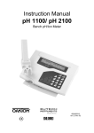
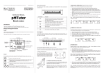
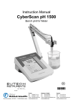
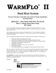
INSTRUCTION MANUAL
CyberScan pH/Ion 510
Bench pH/Ion/mV Meter
68X090811 ver 1.0 12/99
Technology Made Easy…
PREFACE
Thank you for choosing Eutech Instruments’ CyberScan pH 510 pH/mV/Temperature or CyberScan
Ion 510 Ion/pH/mV/Temperature bench meter.
The instruction manual functions in two ways: firstly as a step-by-step guide to help you operate the
CyberScan 510 series meter. Secondly, it serves as a handy reference guide.
The instruction manual is written to cover as many anticipated applications of the CyberScan pH/Ion
510 Bench meter series as possible. If there are doubts in the use of the instrument, do not hesitate
to contact the nearest Eutech Instruments Authorized Distributor or Eutech Instruments at (65) 7786876 or E-mail at [email protected].
Kindly remember to fill in the warranty card and mail back to your authorized distributor.
Eutech Instruments cannot accept any responsibility for any damage or malfunction to the meter
caused by improper use of the instrument.
Note: Eutech Instruments Pte Ltd. reserves the right to make improvements in design,
construction, and appearance of our products without notice.
©
Copyright 1999 Eutech Instruments Pte. Ltd. All rights reserved. Version 1.0 on 12/99
CyberScan pH 510/Ion 510
TABLE OF CONTENTS
1
INTRODUCTION .............................................................................................................................. 3
1.1
1.2
1.3
1.4
2
Introducing the CyberScan Series ............................................................................................................3
Custom LCD .............................................................................................................................................3
Keypad......................................................................................................................................................3
Rear Instrument Panel ..............................................................................................................................4
STARTING UP ................................................................................................................................. 5
2.1
Connecting the Sensor Electrode .............................................................................................................5
2.2
Connecting the Temperature Probe..........................................................................................................5
2.3
Connecting the A/C Adapter .....................................................................................................................5
2.4
Connecting the Chart Recorder ................................................................................................................5
2.5
Connecting the Electrode Holder (Optional) .............................................................................................5
2.6
Steps Prior to Calibration ..........................................................................................................................6
2.6.1
Switching ‘ON’ and ‘OFF’ the meter..................................................................................................6
2.6.2
Selecting Measurement Mode ..........................................................................................................6
2.6.3
Meter Reset ......................................................................................................................................6
2.6.4
Selecting pH Buffer Standard ...........................................................................................................6
3
CALIBRATION ................................................................................................................................. 7
3.1
3.2
3.3
3.4
4
MEASUREMENT ........................................................................................................................... 12
4.1
4.2
4.3
4.4
4.5
5
Automatic Temperature Compensation (ATC)........................................................................................12
Manual Temperature Compensation (MTC) ...........................................................................................12
Taking Measurements ............................................................................................................................12
HOLD Function .......................................................................................................................................13
Storing and Recalling Data from Memory ...............................................................................................13
SETUP FUNCTIONS...................................................................................................................... 15
5.1
5.2
5.3
5.4
6
pH Calibration ...........................................................................................................................................7
Ion Concentration Calibration (For Ion 510 only) ......................................................................................9
mV Calibration ........................................................................................................................................10
Temperature Calibration .........................................................................................................................11
P1.0
P2.0
P3.0
P4.0
Clear Memory ................................................................................................................................15
Viewing Electrode Diagnosis ........................................................................................................16
Selecting pH Buffer Standard ........................................................................................................17
Meter Reset...................................................................................................................................17
pH Electrode Maintenance........................................................................................................... 18
6.1
Storage ...................................................................................................................................................18
6.2
After Use.................................................................................................................................................18
6.2.1
Electrolyte Replacement (for refillable electrodes only) ..................................................................18
6.3
Electrode Cleaning .................................................................................................................................18
6.4
pH Electrode Rejuvenation .....................................................................................................................19
6.4.1
Rejuvenation Procedure .................................................................................................................19
7
TROUBLESHOOTING GUIDE....................................................................................................... 20
7.1
7.2
8
Error Messages ......................................................................................................................................20
Troubleshooting ......................................................................................................................................20
ADDITIONAL INFORMATION ....................................................................................................... 21
8.1
pH and Temperature...............................................................................................................................21
8.2
Use of Standard pH Buffers ....................................................................................................................21
8.3
Standard pH Buffers ...............................................................................................................................21
8.4
List of Accessories ..................................................................................................................................22
8.4.1
pH Buffers/Sachets, Reference Electrolyte & Others......................................................................22
8.4.2
Ion Selective Electrodes (ISE) ........................................................................................................22
8.4.3
pH & ORP Electrodes .....................................................................................................................23
8.5
Specifications..........................................................................................................................................24
8.6
Warranty .................................................................................................................................................24
8.6.1
Return of Items ...............................................................................................................................24
2
CyberScan pH 510/Ion 510
1 INTRODUCTION
1.1
Introducing the CyberScan Series
The Eutech Instruments’ CyberScan pH 510 and CyberScan Ion 510 bench meters are microprocessor-based
which incorporates new ASIC (Application Specific Integrated Circuit). It is designed with many advanced userfriendly features with the convenience of users in mind. The meters are capable of storing and recalling up to
50 data sets in its non-volatile memory. In addition, as a space saver, an optional swivel electrode holder can
be attached at the either side of bench meter for resting the electrodes and probes during operation.
The CyberScan pH 510 meter is capable of measuring pH/ORP with Temperature; while the CyberScan Ion
510 meter measures Ion Concentration/pH/ORP with temperature. It is equipped with a large customized LCD
(Liquid Crystal Display) with simultaneous display of the measured values for easy reading. It is most ideal for
routine pH/Ion Concentration measurement in indoor applications.
1.2
Custom LCD
The CyberScan 510 meter is characterized by a large custom dual LCD. The display has mode annunciators
for pH, mV, ppm and temperature readings. The secondary (lower) display shows the temperature reading
simultaneously with the primary (upper) display that shows the measured values of pH, ppm or mV. Special
annunciators such as units of measure, error message, graphical icons and modes of operation are arranged
around both primary and secondary display to give you a comprehensive yet uncluttered display.
SETUP – The meter
is in SETUP mode.
READY- The measured
value has stabilized.
HOLD- The displayed
value has been frozen.
MEAS- The instrument is in
the measurement mode.
SETUP
Buffer - Prompts user
to select buffer during
calibration, or indicates
buffer error when
flashing together with
the ERR annunciator.
1.3
MEAS
CAL
READY
MEM
MEM- Data is stored
into memory
R.mV
pH
HOLD
ON
OFF
ERR - An error in
operation has occured.
CAL - The instrument is in
the calibration mode.
Shows the
respective mode
of operation.
ppm
MEM
ERR
CF
pH
AM PM
ATC
pH – Indicates buffer
values of respective
USA or NIST buffer
option set.
ELECTRODE- indicates
electrode error when it
appears with ERR.
ATC (Automatic
Temperature
Compensation)
activated. If ATC is not
displayed, temperature
probe is not connected.
In this case the Manual
Temperature
Compensation is
activated.
Keypad
A large splashproof membrane keypad with tactile feedback makes meter easy to use. Names and symbols
describe the function button controls.
Key
Measurement Mode
Calibration / Setup Mode
ON/OFF
Powers the meter ON/OFF. When the meter is
switched on, it automatically starts in the last
mode of operation.
3
CyberScan pH 510/Ion 510
CAL/MEAS
MODE
Toggles between the measurement and
calibration modes of the meter. In SETUP
mode, pressing CAL/MEAS key returns to the
measurement mode.
Toggles between the different measurement
modes available pH/Temperature/mV/Ion.
Switches from pH to Temperature in pH
calibration mode
MI/▲
▲
MI inputs measurements into memory and
scrolls through memory values.
▲ scrolls values in mV calibration mode
and selects temperature values and ion
options in calibration mode. Scrolls to
next program in the SETUP mode.
MR/▼
▼
MR recalls measurements from memory and
scrolls through memory values.
▼ scrolls values in mV calibration mode
and selects temperature values and ion
options in calibration Scrolls to next
program in the SETUP mode.
HOLD
Freezes a measurement on the display. Press
again to get current readings.
ENTER
Enter functions in the memory mode.
Confirms and enters the value selected
for calibration.
You can also configure functions like Meter Reset, Memory Clear and Selection of pH Buffer Standard via its
keypad. Please refer to Section 5 for more information on the above functions.
1.4
Rear Instrument Panel
The CyberScan 510 series meter provides a complete set of connectors for the various accessories commonly
used. Listed in the table are the details of the connections that you can make.
Rear View of Meter
Connection
ATC
Function
For phono jack connection from the temperature probe for Automatic Temperature
compensation. The probe should be a 30KΩ thermister type.
INPUT
For connection to sensor electrodes with BNC type connectors. The meter accepts any pH,
ORP or ISE with BNC connector. Always ensure that the connector is clean and dry.
REF
For connection to pin type reference electrode normally used with half cell (mono) type pH
electrodes or ISEs.
REC
For connection to strip chart recorders. Use subminiature plug with positive tip.
GND
For connection to the ground earth jack (standard tip connectors).
DC
For connection for the AC/DC power adapter (optional accessory – see section on
Specifications for details)
4
CyberScan pH 510/Ion 510
2 STARTING UP
Connect the accessory connectors at the rear of the instrument panel. During operation, it is important that
water does not get onto the BNC connector. Also avoid touching the connector with soiled or wet hands.
2.1
Connecting the Sensor Electrode
Slide the electrode connector of the electrode over the socket of the meter’s BNC connector marked ‘INPUT’.
The meter can accept any standard pH, ORP, or Ion Selective Electrode with a BNC connector. Align the slot
of the electrode connector with the posts of the socket. Rotate the connector clockwise until it locks. For
separate reference electrodes, push the electrode pin into jack marked ‘REF’.
2.2
Connecting the Temperature Probe
Insert the temperature probe (provided) into the connector marked ‘ATC’.
2.3
Connecting the A/C Adapter
Slide in the adapter jack of the A/C adapter into the back panel marked ‘DC’ until it is firmly seated. Ensure that
the power is switched off before installation and correct voltage of adapter is used.
2.4
Connecting the Chart Recorder
You can connect chart recorders or external output devices for continuous printout. Plug in the input connector
and ground pin of the chart recorder into the ports marked ‘REC’ and ‘GND’ respectively.
Sensor electrode
Temp. probe
2.5
Chart recorder
Separate ref. electrode
Ground
AC/DC Adapter
Connecting the Electrode Holder (Optional)
Bottom of Meter
The integral electrode holder serves as a handy holder
for mounting a few pH/Ion electrodes or a temperature
probe during measurement or when idle.
The CyberScan bench meter’s base plate has a side
metal bar to which you can attach an integral swivel
electrode holder. You can mount the electrode holder
on either right or left side of the meter.
To position the electrode arm:
Use a Phillips screwdriver to remove the screw holding
the electrode holder. Slide the side metal bar until the
second screw slot lines up with the original screw
hole. Use the screw removed earlier to secure the
electrode holder into position. Note the side metal bar
is reversible. If desired, remove screw holding
electrode holder base and slide out of brackets, Slide
base into brackets on opposite side and tighten screw.
5
CyberScan pH 510/Ion 510
To install electrode arm to the meter:
Electrode Arm
To mount the electrode arm into the metal rod on the side
bar, align the slot with the metal rod and base of electrode
arm. Push it downwards until it fully sits into position. Avoid
using excessive force when fixing or removing. The
electrode arm is ready for use.
Side Metal Bar
2.6
2.6.1
Steps Prior to Calibration
Switching ‘ON’ and ‘OFF’ the meter
Press ON key to switch meter on. All the LCD segments will display momentarily for a few seconds and the
LCD then switches to the last measurement mode. To switch meter off, press OFF key.
2.6.2
Selecting Measurement Mode
The measurement modes available for the CyberScan pH 510 meter are pH, mV (for ORP) and Temperature,
while the CyberScan Ion 510 meter has Ion, pH, mV and Temperature measurement modes. Select the correct
mode of operation by pressing the MODE key, and each press takes you to next measurement mode. When
selecting a particular parameter the respective mode annunciator displays at the right hand side of primary
o
display; these include [pH] for pH, [ C] for Temperature, [ppm] for Ion Concentration and [mV] for Millivolt.
2.6.3
Meter Reset
On first use, it is not necessary to reset meter before calibration as it has been factory-calibrated. However if
you wish to reset the meter to factory default refer to this Section 5.4. Note re-calibration of meter is required
before measurement after the meter is reset.
Likewise if you wish to prepare a new set of measurement, you may reset all the last calibrated pH values for
added convenience. Caution: All calibration values and memory data will be erased upon activation. Recalibration is required.
2.6.4
Selecting pH Buffer Standard
The meter is capable of calibrating based on either USA or NIST pH buffer standards. Please refer to Section
5.3 P3.0 for details on how to change the USA buffer standard to the NIST standard on the meter itself. Refer
to Section 8.4.1 for more details on pH buffer standards available.
NOTE: Remove protective rubber cap or storage bottle (if any) of the electrode before proceeding with
measurement or calibration. Take care not to exert too much force as this may cause damage to the electrode.
Whenever the electrode is not in use, put it into storage bottle or rubber cap provided. Refer to the Section 6
on Probe Maintenance for more details.
6
CyberScan pH 510/Ion 510
3 CALIBRATION
3.1
pH Calibration
The CyberScan 510 series bench meter is capable of multi-point calibration (up to 3 points) for unprecedented
accuracy across the measurement range. The 3-point calibration offers flexibility of calibrating using either USA
or NIST buffer standards with their 3 internationally accepted calibration points namely:
USA standard buffer options: pH 4.01, pH 7.00 and pH 10.01
NIST standard buffer options: pH 4.01, pH 6.86 and pH 9.18.
For ATC measurements, attach the temperature probe to the meter. The ATC mode annunciator shows on the
display. Insert the probe into the solution to be measured so that the sample temperature can be recorded and
pH readings automatically temperature compensated. If manual temperature compensation is preferred, do not
plug a temperature probe into the meter.
DO NOT REUSE SOLUTIONS AFTER CALIBRATION. Contaminants in the solution can affect the calibration,
and eventually the accuracy of the measurements. All new calibrations will override existing stored calibration
data at these calibration points.
It is recommended that you perform at least a 2-point calibration using buffers that bracket (one above and one
below) the expected sample range, starting with pH 7 buffer firstly. You can perform a 1-point calibration, but
make sure that the buffer value is close to the sample value you are measuring. Select a pH 4, 7 or 10 buffer in
sachets or bottles from Eutech standard buffer solutions.
1.
Press ON/OFF key. All the LCD segments will be displayed
momentarily. The LCD switches to pH measurement mode. If
necessary press MODE key to select pH mode.
NOTE: The meter starts in the same measurement mode that it
was switched off.
2.
The customized LCD display will indicate the following:
Display
MEAS
pH
o
C
ATC
3.
Remarks
Measurement mode is selected
Unit of measurement
Measured temperature reading
Automatic Temperature Compensation
Rinse both pH electrode and temperature probe well with
deionized water or rinse solution. (Do not wipe the electrode as
this may cause a build-up of electrostatic charge on the
glass surface!).
One Point Calibration
4.
Select the first pH buffer, say pH 7.00 buffer and pour some into a
clean container.
5.
Dip both probes into the standard calibration buffer. The end of
the probe must be completely immersed into the buffer. Stir the
probes gently to create a homogenous solution.
6.
Press CAL/MEAS key to enter the pH calibration mode. The
annunciator [CAL] appears on top of the LCD to indicate the
meter is in pH calibration mode. The upper display will show the
measured reading while the lower display indicates appropriate
pH standard buffer solution being used.
NOTE: The meter automatically recognizes the buffers in the
buffer standard you have set in the SETUP mode, i.e. either USA
(pH 4.01, 7.00 or 10.01) or NIST (pH 4.01, 6.86 or 9.18) buffers.
NOTE: To exit from pH calibration mode without confirming
calibration, DO NOT press ENTER key in step 9. Press the
CAL/MEAS key instead.
7
Figure 1: 1st-point calibration
CyberScan pH 510/Ion 510
7.
Wait for the measured pH value to stabilize (when the [READY]
indicator displays in the left-hand corner).
8.
If the upper measured display is not within the buffer acceptable
window (refer to Hint below) an error message and the
electrode icon flash upon pressing the ENTER key. Refer to
Section 7 on Troubleshooting Guide. Check electrode condition
and recalibrate. Press CAL/MEAS key to exit calibration and
resume to the measurement mode.
Figure 2: Calibration error
9.
Press the ENTER key. The upper display flashes the calibration
value momentarily. The calibration point is successfully stored
in the meter.
10. If you are performing a one-point calibration, press CAL/MEAS
key to return to the measurement mode and start taking pH
readings (see Figure 1).
Figure 3: 2nd-point calibration
Two to Third Point Calibration
11. If you are performing a multi-point calibration (i.e. second-point
or more) go to step 12.
12. Rinse the probes with deionized water or rinse solution to avoid
cross contamination, and place them in the next pH buffer, say
pH 4.01 buffer. The meter automatically switches to the next pH
buffer solution selected in the lower display
13. Wait for the measured pH value to stabilize (when the [READY]
indicator displays in the left-hand corner). (see Figure 3).
Figure 4: 3rd- point calibration
HINT: If the selected
buffer value is not within
the accepted window (see
below) from the measured
value: the electrode and
buffer icon blink and ERR
annunciator appears next
to the secondary display.
(See Figure 2 above)
Press CAL/MEAS key to
exit the ERR condition.
Window of Accepted
Values:USA
4.01
±1.00
7.00
±1.50
10.01 ±1.00
−−−−−−−−−−−−−−−−−−−−
NIST
4.01
±1.00
6.86
±1.25
9.18
±1.00
14. Press the ENTER key. The upper display flashes the calibrated
value. The calibration point is now stored in the meter.
15. If you are performing a two-point calibration, then press the
CAL/MEAS key to return to the measurement mode and start
taking pH readings.
16. If you are performing a three-point calibration go to step 17.
17. Rinse the probes with deionized water or rinse solution, and
place them in the next pH buffer, say pH 10.01 buffer. The
meter automatically switches to the next pH buffer solution
selected in the lower display.
18. Wait for the measured pH value to stabilize (when the [READY]
indicator displays in the left-hand corner) (see Figure 4).
19. Press the ENTER key. The upper display flashes the calibration
value. The calibration point is now stored in the meter. The
meter automatically returns to the pH measurement mode after
a three-point calibration is performed.
8
CyberScan pH 510/Ion 510
3.2
Ion Concentration Calibration (For Ion 510 only)
The CyberScan Ion 510 meter is capable of up to 3-point ion calibration (minimum 2 point) with choice of 4
options to ensure accuracy across the entire measurement range. Ion calibration options include 0.10, 1.0,
10.0 or 100.0 ppm. All calibration should be at least one decade apart from each other. For example you may
perform 3 point calibration to 0.10, 1.0 and 10.0, or 2-point calibration to 10.0 and 100.0. If 1-point calibration is
performed an error message “Er2” is displayed. If any of calibration points are not within 1 decade, an error
message “Er4” will be displayed at the end of calibration process.
Calibration values are successfully stored if the ISE slope is within the specified tolerance of 15mV/decade
(minimum) and 90mV/decade (maximum), otherwise an error message “Er3” is displayed (see Figure 7). The
calibration values are not stored into the meter’s built-in memory if any error message appears after each
calibration process. Re-calibration is necessary as calibration is unsuccessfully attempted in this instance.
Check that your ISE and standard solutions are in good working conditions.
Ensure that you use new or fresh standard solutions during calibration. Do not reuse ion standard solution as it
may be contaminated and affect the calibration and accuracy of measurements. Always store standard
solutions in a dry, cool environment if possible. Before use, remove plastic protective cap of ISE. Briefly rinse
the electrode with clean deionized water to remove any residues.
Rinse probes before and after each calibration or sample measurement to avoid cross-contamination. For
more details please refer to Manufacturer’s care and maintenance guide. Note the Ion calibration values will
be lost once power is disconnected; only pH and mV calibration values will be retained.
1.
2.
3.
Connect an Ion Selective Electrode (ISE) to the BNC input connector
on the back of the meter. Turn the meter ON.
Press MODE key (if needed) to select ion measurement mode. If
there is no old calibration values, then the meter displays “---“ in the
upper display in measurement mode.
Dip the ISE into the first calibration standard. Make sure to start with
the calibration standard that has the lowest concentration and move
up to the standards that have higher concentrations.
Swirl it gently. Press CAL key to enter the ion calibration mode. The
[CAL] indicator appears above the upper display and the upper
display reads “0.10”. The lower display shows the corresponding
absolute mV value of sample measured.
4.
The first calibration point of 0.10 ppm appears on the display. If you
DO NOT wish to calibrate to this point, press ▲ (up arrow) to skip and
continue to the next calibration point of 1.0 ppm or 10.0 ppm.
5.
If you DO wish to calibrate to 0.10 ppm, allow the mV reading to
stabilize. When the reading stabilizes the [READY] indicator will
appear on the display. Stabilization may take a few minutes
depending on electrode and standard concentration.
6.
Press ENTER key to confirm your first point calibration (see Figure 5).
After calibration, the display will show the next calibration option, i.e.
1.0 ppm. Proceed by rinsing the electrode with deionized water
before placing it in the next calibration standard i.e. 1.0 ppm.
7.
Allow the meter to stabilize in the next calibration standard. Wait for
the [READY] indicator to appear before you press the ENTER key to
confirm the second calibration point. The upper display flashes
momentarily then moves to the next calibration point of 10.0 ppm.
NOTE: If you are performing a 2-point ion calibration, press
CAL/MEAS key. “SLO” appears in the upper display with the [mV]
indicator and the number in the lower display is the electrode slope in
mV (see Figure 6). You are ready to take ion measurements. If the
slope is outside the acceptable limits or if incorrect standards have
been used the upper display will show “Er3”.
9
Figure 5: 1st-point calibration
CyberScan pH 510/Ion 510
If you are performing a 3-point calibration, rinse off the electrode
with deionized water and place it in the next calibration standard
and proceed as described earlier.
8.
Allow meter to stabilize in the next calibration standard. Wait for the
[READY] indicator to appear before you press the ENTER key to
confirm the third calibration point. The upper display flashes for a
few seconds then “SLO” appears in the upper display with the mV
indicator, the number in the lower display is the average electrode
slope in mV (see Figure 6). After a few seconds the meter reverts
to the measurement mode. You are now ready to take ion
measurement.
NOTE: All the calibration values are successfully stored. Otherwise
error message will appear in the LCD if the calibration was
unsuccessful with no values stored into memory.
HINT: Minimum of 2
points and maximum
of 3 points are
allowed for Ion
Calibration. All
calibration points
should be at least one
decade apart, i.e.
valid calibration
points are 0.1, 1, 10
ppm or 1, 10, 100 ppm
or 0.1, 1 ppm or 1, 10
ppm or 10, 100 ppm.
NOTE: You may compare the average electrode slope value with
the expected slope value for your electrode from your electrode
manual to verify electrode operation.
Figure 6: Slope value in mV
Figure 7: Error message Er3
if slope not within range
3.3
mV Calibration
1.
Make sure the meter is on and if necessary, press the MODE key to
select mV mode. The [mV] indicator appears in the upper right-hand
corner of the display.
2.
Press the CAL/MEAS key. The [CAL] indicator appears above the
upper display that displays the relative mV reading. The lower
display shows the absolute mV value.
NOTE: If you have never calibrated relative mV or if the meter has
been reset, the value shown in the upper display is the same as the
absolute mV value. The range of adjustment is -1999 mV to 1999
mV (resolution is 1 mV); of which from -199.9 to 199.9 mV the meter
gives you a resolution of 0.1 mV.
3.
Press ▲ or ▼ keys to enter the relative mV value that matches your
desired reading.
4.
Press the ENTER key to confirm the reading and the meter
automatically returns to the measurement mode. The upper display
now shows the relative mV reading. The [R.mV] indicator appears in
the upper right hand corner.
NOTE: New mV calibrations will override existing stored mV
calibration data. The meter retains stored mV calibrations even when
the meter is turned off.
10
CyberScan pH 510/Ion 510
3.4
Temperature Calibration
In this calibration procedure, the ATC probe is attached to the meter and the [ATC] annunciator is displayed on
the right hand side of the LCD.
1.
Dip the temperature probe into a solution of known temperature,
such as a temperature bath for a few minutes until the temperature
probe stabilizes.
2.
To perform temperature calibration, you must be in the pH
measurement mode.
3.
Press MODE key to switch to the pH measurement mode if you are
in the mV or ion measurement modes.
4.
Press CAL/MEAS key to enter pH calibration mode.
5.
Press MODE key again to switch to temperature calibration.
6.
Press ▲ or ▼ key to scroll to the correct temperature value
corresponding to the known solution temperature. The meter allows
o
o
a limit of ± 5 C variation (with 0.1 C resolution) of the input
reading, and of the original displayed reading.
7.
Once you selected the correct temperature, press ENTER key to
confirm. The meter automatically returns to the pH measurement
mode.
11
CyberScan pH 510/Ion 510
4 MEASUREMENT
4.1
Automatic Temperature Compensation (ATC)
For ATC measurements, simply attach the temperature probe into the
meter (see Section 2.2). The [ATC] annunciator lights up on the LCD.
NOTE: If you are using a temperature probe, the probe must be
submersed in the liquid you are measuring so that the sample
temperature can be recorded and compensated for.
4.2
Manual Temperature Compensation (MTC)
Important: For MTC, you must disconnect the temperature probe.
1.
Switch the meter on. Press the MODE key to select pH mode.
2.
Press the CAL/MEAS key to enter pH calibration mode. The CAL
annunicator appears above the upper display.
3.
While in pH calibration mode, press the MODE key to enter
temperature compensation mode. The upper display shows the
current temperature setting and the lower display shows the default
value 25.0 ºC (if the meter has never been manually set for
temperature) or the last manually set value if the meter has
previously set for MTC. If you have not set the current temperature
setting the upper display will also show the default value of 25.0 ºC.
4.
Check the temperature of your sample using an accurate
thermometer.
5.
Press ▲ or ▼ key to offset the temperature to the measured value
from step 4.
6.
Press ENTER key to confirm the selected temperature and return to
the pH measurement mode.
7.
To exit this program without confirming the MTC value, DO NOT
press ENTER key in step 6. Press CAL/MEAS key instead.
NOTE: The meter will compensate pH reading for the manually set
temperature.
4.3
Taking Measurements
Be sure to remove the electrode soaker bottle or protective rubber cap on the electrode before measurement.
To take readings:
1.
Rinse the electrode with distilled or tap water before use to remove any impurities adhering to the
electrode body. If the pH electrode had dehydrated, soak it for 30 minutes in EC-RE005 electrode storage
solution. (See Electrode Care - Section 6)
2.
Press ON key to switch on meter. The [MEAS] annunciator appears on the top center of LCD. The ATC
annunciator appears in the lower right hand corner to indicate ATC if a temperature probe is plugged.
(For MTC, refer to Section 4.2).
3.
Dip the electrode and temperature probe into the sample, making sure that the glass bulb of the electrode
must be completely immersed into the sample. Stir the probes gently to create a homogeneous sample.
4.
Allow time for reading to stabilize. When the readings stabilize, a [READY] annunciator displays. The
READY mode shows the readings are stable within a range of ±0.01 pH. When this occurs, the [READY]
annuciator appears on the top left side of LCD. Take the reading.
5.
To toggle between pH and mV in the pH510, or to toggle between pH, mV and Ion in the Ion 510, press
the MODE key.
12
CyberScan pH 510/Ion 510
4.4
HOLD Function
This feature lets you freeze the value of the measured reading. HOLD can be used anytime when in [MEAS]
mode. You can store the held reading into memory by pressing MI key.
HOLDing a measurement
To hold a measurement, press the HOLD key while in measurement
mode. [HOLD] annunciator will appear on the display.
Releasing a Held Value
To release the held value, press HOLD key again. [HOLD] annunciator
will disappear from the LCD. Continue to take measurements.
4.5
Storing and Recalling Data from Memory
The meters allow up to 50 data sets to be stored and recalled into its non-volatile memory in the Last-In-FirstOut (LIFO) sequence. The data set is also stored with specified location as indicated on the display. However
you can selectively view the data at that specified location for added convenience.
pH 510 meter:
•
pH and Temperature
•
mV (or Relative mV) and temperature
Ion 510 meter:
•
pH and Temperature
•
mV (or Relative mV) and temperature
•
ion and mV
For example you can store 32 pH and 18 mV values for the CyberScan pH 510 or 15 ion, 12 mV and 23 pH
values for the CyberScan Ion 510.
Memory Input
This feature allows you to store measurement readings into memory for
later review. This mode can be invoked at any time during measurement
mode or when the reading is frozen ([HOLD] annunciator is displayed on
LCD by the activation of HOLD key).
To store reading:
1.
2.
During any measurement or HOLD function, press the MI key once
to input data into the memory.
[MEM] annunciator, “StO” and memory number will flash
momentarily. The meter then returns to the measurement mode.
3. To continue storing data, press MI key again.
NOTE: If the memory is full, the first value stored will be erased to
create space for the new value.
13
CyberScan pH 510/Ion 510
Memory Recall
1.
In the measurement mode, press MR key once to retrieve the last
reading stored. The memory location screen – “MEM”, “LOC” and
the memory number – will flash on the display.
2. Press the ENTER key to recall the reading stored under that memory
number.
3. If necessary, you can selectively choose to view any data that is
stored by using ▲ or ▼ key. For example to view the third data
location set to LOC 3 from last stored location of LOC 5. Use ▲ or ▼
key to set to LOC 3. Press ENTER key to retrieve the data from this
location.
4. To continue reviewing additional stored data, press ENTER key
again. For this instance the next location LOC 2 will be displayed.
5. To exit Memory Recall and operate meter, press the MEAS key to
return to the measurement mode.
NOTE: Readings stored in memory are retained even of the unit is turned
off. To erase all readings stored in memory, see Program P1.0.
14
CyberScan pH 510/Ion 510
5 SETUP FUNCTIONS
The advanced SETUP mode lets you customize your meter’s preferences and defaults:
P1.0: Memory Clear (Clr)
P2.0: Viewing electrode data (ELE)
P3.0: Selecting buffer sets (bUF)
P4.0: Reset to factory default settings (rSt)
To enter the SETUP mode:
1.
Turn meter OFF.
2.
With meter off, press and hold the MODE key and press and release the ON key. The display will show
the [SETUP] indicator. If the display indicates you are in the measurement mode turn the meter off and try
step 2 again until [SETUP] appears.
NOTE: To exit the SETUP mode at anytime without confirming changes press CAL/MEAS until the
measurement mode appears. You may have to press CAL/MEAS key two times before the meter reverts to the
measurement mode.
5.1
P1.0 Clear Memory
Use this program to clear all memory values when you need to store a
new series of values. This lets you avoid confusing the old values with
the new ones. NO is the default setting.
1.
Enter the SETUP mode as described above. The meter
automatically goes to program P1.0 Clr appears in the upper display
and P1.0 in the lower display.
2.
Press the ENTER key to access the program and the lower display
shows either (depending on last option selected or factory default
i.e. nO).
3.
Use ▲ or ▼ key to toggle between “nO” or “YES”
4.
Press ENTER key to confirm selection and return to the SETUP
mode. To continue to the next SETUP, press ▲ or ▼ key to select a
new program. Otherwise press the CAL/MEAS key to return to the
measurement mode.
15
CyberScan pH 510/Ion 510
5.2
P2.0 Viewing Electrode Diagnosis
This program lets you check the electrode parameters for diagnostic purposes. Depending on the last display
mode, displayed electrode information varies. These readings can only be viewed.
Last Display Mode
pH
Ion
mV
Electrode Property
Offset
Slope
in mV
%
in mV
in mV
-
1.
Enter the SETUP mode as described above. The meter
automatically goes to program 1.0.
2.
Press ▲ and ▼ key to scroll through the programs until you view
ELE in the upper display and P2.0 in the lower display. The
electrode annunciator also appears.
3.
Press ENTER key to access the program P2.0. The lower display
will read P2.1.
The information you will see in Program P2.0 will depend upon which
MODE the meter was in prior to shutting the meter off:
In the pH measurement MODE:
P2.1 shows the mV offset of the electrode. Press ENTER key to go
to P2.2 (see Figure 8).
P2.2 shows the slope in % of the electrode.
In the mV measurement MODE:
P2.1 shows the mV offset of the electrode (see Figure 9).
In the Ion measurement MODE:
P2.1 shows the average slope of the electrode (see Figure 10).
4. To exit P2.0 program press ENTER key until ELE is in the upper
display and P2.0 is in the lower display. Press ▲ or ▼ key to select a
new program OR press CAL/MEAS key to return to the
measurement mode.
Figure 8: slope in %
Figure 9: mV offset
Figure 10: Average slope (mV)
16
CyberScan pH 510/Ion 510
5.3
P3.0 Selecting pH Buffer Standard
This program lets you select between two standard calibration buffer sets,
depending upon your requirements.
The available standards are USA and NIST.
1.
Enter the SETUP mode as described in this section earlier. The
meter automatically goes to program P1.0.
2.
Press ▲ and ▼ key to scroll through the programs until you view
“bUF” in the upper display and P3.0 in the lower display. The buffer
annunciator also appears.
3.
Press ENTER key to access the program P3.0. The lower display will
read either ”USA” or “nSt” (depending on the previous setting you
have made; factory default is USA.)
4.
Press ▲ or ▼ key to select the buffer set you require:
•
USA buffers: 4.01, 7.00 and 10.01
•
nSt buffers: 4.01, 6.86 and 9.18
5.
To confirm the buffer standard, press ENTER. All the characters on
the display will flash momentarily and then returns to P3.0.
6.
To exit P3.0 program press ▲ or ▼ key to select a new program OR
press the CAL/MEAS to return to the measurement mode.
5.4
P4.0 Meter Reset
This program resets and clears all memory data and calibration data
except temperature calibrated value which will be retained. NO is the
default setting.
1.
Enter the SETUP mode as described in this section earlier on. The
meter automatically goes to program P1.0.
2.
Press ▲ and ▼ key to scroll through the programs until you view rSt
in the upper display and P4.0 in the lower display. The mV and pH
annunciators also appears.
3.
Press the ENTER key to access the program P4.0. The lower
display will read NO.
4.
Press ▲ or ▼ key to select “NO” or “YES”. Select YES erases all
calibration values for all modes (pH, mV and ion) and all memory
values.
5.
To confirm the reset, make sure YES is selected and press ENTER.
All the characters on the display will flash for a second then the
meter returns to the measurement mode.
NOTE: Once YES is selected and ENTER key is pressed, the reset
program clears all old calibration data and memory data. The data is no
longer retrievable. You must calibrate the meter before taking any new
measurements. Meter will however retain buffer set selection (NIST or
USA).
17
CyberScan pH 510/Ion 510
6 pH Electrode Maintenance
pH electrodes are susceptible to dirt and contamination and need to be cleaned regularly depending on the
extent and condition of use. Refer to Section 6.3 for more details on cleaning pH electrode.
6.1
Storage
For best result, always keep the pH electrode bulb wet, preferably with use of Eutech’s Storage Solution (ECRE005). Other storage media like pH 7 buffer, storage solution or tap water are also acceptable. Avoid storing
in deionized water as this causes the electrode’s response to become sluggish. The protective rubber cap or
container filled with the buffer solution provides ideal storage for long periods.
6.2
After Use
After measurement is complete, follow the sequence below for storage.
a) Wash the electrode and reference junction in de-ionized water
b) Close the refilling hole by returning its rubber sleeve or stopper cap into position (Necessary for only
refillable electrodes).
c)
Store the electrode as mentioned above (see Storage).
6.2.1
Electrolyte Replacement (for refillable electrodes only)
The reference electrolyte needs to be refilled when the pH electrode has been used for an extended period, or
when the internal electrolyte has dried up. To accomplish this, follow the procedure:
1.
Remove the protective rubber cap or sleeve to expose the filling port of the electrode. Remove the old
reference electrolyte by flushing out with a syringe and a flexible tube.
2.
Add in fresh electrolyte until it reaches the level of the refilling port. The reference electrolyte used should
be 4M KCl (EC-RE001). Replace the rubber sleeve.
Sleeve
Rubber
Stopper
3.
Rinse the liquid junction with de-ionized water and tap dry.
NOTE: If these steps fail to restore normal electrode response, you may attempt to rejuvenate it. (See:
Electrode Rejuvenation).
6.3
Electrode Cleaning
pH electrodes that are mechanically intact and not in use for a short period of time can be restored to normal
performance by one or combination of following procedures:
a) Salt deposits
Dissolve the salt deposits by immersing the electrode in a container filled with some tap water for ten to fifteen
minutes. Then thoroughly rinse with de-ionized water.
18
CyberScan pH 510/Ion 510
b) Oil / Grease Films
Wash the pH electrode bulb in mild detergent and water. Rinse electrode tip with de-ionized water.
c) Clogged Reference Junction
60 - 80 oC
KCl
Heat for 10 minutes
o
Heat a dilute KCl solution to 60-80 C. Place the sensing portion of the pH electrode into heated KCl solution
for approximately 10 minutes (as shown above). Care must be taken when performing this procedure. Allow
electrode to cool while immersing in some unheated KCl solution.
d) Protein Deposits
Use Eutech’s Protein Cleaning Solution EC-DPC-BT to remove any protein that is deposited onto pH electrode.
Allow the electrode to stand in this solution for five to ten minutes.
6.4
pH Electrode Rejuvenation
CAUTION: Proper protective eyewear and precautionary measures must be used when performing the
rejuvenation procedure as it involves the use of concentrated acid and alkaline.
Generally, if procedure of storage and maintenance had been closely followed, the pH electrode can be used
immediately. However, should the electrode response become sluggish, it may be possible that the glass bulb
has dehydrated. Immersing the electrode in an ideal storage solution (e.g. buffer pH 4 solution) for 1- 2 hours
can dehydrate the glass bulb. If this fails, the electrode may require re-activation. At no time should you touch
or rub the glass bulb as this causes the build-up of electrostatic charge. If the above procedure does not reactivate electrode to acceptable status, try rejuvenating electrode by following the procedure outlined below.
6.4.1
1.
2.
3.
4.
5.
6.
Rejuvenation Procedure
Dip and stir the electrode in freon or alcohol for 5 minutes.
Leave the electrode in tap water for 15 minutes.
Dip and stir the electrode in concentrated acid (e.g. HCl, H2SO4) for 5 minutes.
Repeat Step 2.
Dip and stir in strong base (NaOH) for 5 min. Leave for 15 minutes in tap water.
Test with standard calibration buffer solutions.
Finally, test with standard calibration buffer solutions to see if the electrode yields acceptable results. You may
repeat steps ‘c’ to ‘f’ again for better response (maximum 3 times). If the response does not improve, then the
electrode has completed its useful life. Replace with a new electrode.
19
CyberScan pH 510/Ion 510
7 TROUBLESHOOTING GUIDE
7.1
Error Messages
The table provides a quick guideline for diagnosis of possible problems indicated by the messages generated
by the CyberScan 510 meter series. The table also provides possible solutions to problems encountered.
ERROR MESSAGE
INDICATES
CAUSE
CORRECTIVE ACTION
Err. 2 (in upper display)
during Ion calibration
Too few calibration
points
Meter calibrated with only 1point in ion calibration
Recalibrate using 2 or more
points
Err. 3 (in upper display)
during Ion calibration
Slope error
Ion calibration solution not
within acceptable range
(15mV to 90mV/decade)
Recalibrate using fresh ion
solutions
Replace electrode.
Err. 4 (in upper display)
during Ion calibration
Calibration points
more than 1 decade
apart
Calibration points more than 1
decade apart
Recalibrate using calibration
points 1 decade apart.
Err (annunciator)
Wrong keypad input
Button does not work in the
current operation mode
Release key. Select valid
buttons depending on mode.
Electrode icon (indicator)
Calibration error
Buffer value does not match
value displayed or electrode is
disconnected or failing
Use fresh buffer solution or
check electrode connection.
Electrode not connected
Make sure electrode is
connected
Ur or Or (in upper display)
Electrode clogged, dirty or
broken
Measurement is under range
or over range
7.2
Possibly replace electrodes.
Clean or replace electrode
Treat samples to bring within
meter measuring range
Troubleshooting
PROBLEM
No display
PROBABLE CAUSE
REMEDIAL ACTION
a) Mains power not switched on.
a) Switch on the power supply.
b) AC Adapter socket not inserted properly.
b) Re-insert AC Adapter socket.
a) Insufficient reference electrolyte in
electrode.
a) Fill electrode with reference electrolyte.
b) Broken electrode
b) Replace electrode.
c) External ‘noises’ or induction ( e.g.
electrical ‘noise’ caused by a nearby
motor)
c) Remove or switch off interfering device.
d) Dirty electrode.
d) Clean the electrode. Rejuvenate if necessary.
Slow response
a) Dirty electrode.
a) Clean electrode. Rejuvenate if necessary.
Meter not
responding to key
press
a) HOLD mode in operation.
a) Cancel HOLD mode. Press Hold button.
b) Internal program error.
b) Reset all internal programs by removing A/C
adapter.
Unstable reading
20
CyberScan pH 510/Ion 510
8 ADDITIONAL INFORMATION
8.1
pH and Temperature
Automatic Temperature Compensation (ATC) compensates for temperature changes. Some solutions show an
increase while others a decrease in pH with the same temperature change. Record the solution temperature
along with the pH value, or the measurement may be meaningless. Temperature changes also affect the signal
the pH electrode sends to the meter and causes a loss of accuracy for the reading. To limit the loss of
accuracy during calibration, make the temperature of the pH buffer calibrating solutions and the sample
solution the same.
8.2
Use of Standard pH Buffers
Use standard buffer solutions to calibrate a pH meter before you measure the pH of a sample. They serve as
reference standards for basis of comparison between measurement. The most common USA standard buffers
are the pH 4.01, pH 7.00 and pH 10.01 and the NIST standard buffers are pH 4.01, pH 6.86 and pH 9.18. For
1-point calibration, use a standard buffer of pH 7.00 or a standard buffer whose pH value is close to that of the
sample. Use 2-point calibration when you know the sample is acidic (low pH) or basic (high pH). For acidic
samples, use standard buffers of pH 7.00 and pH 4.01. For basic samples, use standards of pH 7.00 and pH
10.01. Use a 3-point calibration when the sample pH is completely unknown. Use all pH 7.00, pH 4.01 and pH
10.01 calibration solutions.
8.3
Standard pH Buffers
The following table shows the various pH values at different temperature of the solution during calibration. The
o
table also illustrates why a calibration value may be different from the buffer value at 25 C.
Temperature (oC)
pH 4.01 (phthalate)
pH 7.00 (neutral phosphate)
pH 10.01 (carbonate)
0
4.01
7.12
10.33
5
4.01
7.09
10.25
10
4.00
7.06
10.18
15
4.00
7.04
10.11
20
4.00
7.02
10.05
25
4.01
7.00
10.01
30
4.01
6.99
9.95
35
4.02
6.98
9.92
40
4.03
6.97
9.88
45
4.04
6.97
9.85
50
4.06
6.97
9.82
55
4.07
6.98
9.80
60
4.09
6.98
9.77
70
4.12
6.99
9.73
80
4.16
7.00
9.69
90
4.20
7.02
9.66
21
CyberScan pH 510/Ion 510
8.4
8.4.1
List of Accessories
pH Buffers/Sachets, Reference Electrolyte & Others
To order some accessories, send the part name and number to our authorized distributor.
Order Code
8.4.2
Description
EC-BU-1BT
pH 1.68 Buffer Solution (480 ml bottle)
EC-BU-4BT
pH 4.01 Buffer Solution (480 ml bottle)
EC-BU-7BT
pH 7.00 Buffer Solution (480 ml bottle)
EC-BU-9BT
pH 9.18 Buffer Solution (480 ml bottle)
EC-BU-10BT
pH 10.01 Buffer Solution (480 ml bottle)
EC-BU-4BS
pH 4.01 Buffer Sachets (20 ml x 20 pcs. per box)
EC-BU-7BS
pH 7.00 Buffer Sachets (20 ml x 20 pcs. per box)
EC-BU-10BS
pH 10.01 Buffer Sachets (20 ml x 20 pcs. per box)
EC-RE001
Reference Electrolyte (KCl with Ag/AgCl) (480 ml bottle)
EC-RE005
Storage Solution for pH Electrode (480 ml bottle)
EC-DPC-BT
Protein Cleaning Solution (480 ml bottle)
Ion Selective Electrodes (ISE)
Ask our distributors for more details regarding ISE and its standard solutions. The table below lists the range of
electrodes available. All ISE are supplied with 1m cable length and BNC connector.
Ion
Ion
Ammonia (NH3)
Iodide (I-)
Ammonium (NH4+)
Lead (Pb+2)
-
Bromide (Br )
Lithium (Li+)
Cadmium (Cd+2)
Nitrate (NO3-)
+2
Calcium (Ca )
Nitrogen Oxide (NOx)
Carbon Dioxide (CO2)
Perchlorate (CIO4-)
-
Chloride (Cl )
Potassium (K+)
Copper (Cu+2)
Silver / Sulfide (Ag+ / S-2)
Cyanide (CN-)
Sodium (Na+)
Fluoride (F-)
Surfactant (X+, X-)
Fluoroborate
(BF4-)
Water Hardness
22
CyberScan pH 510/Ion 510
8.4.3
pH & ORP Electrodes
There is a wide range of electrodes for the user’s applications. Note that although only one electrode for each
application is shown, there are multiple electrodes available and they are multi-application adaptable. All
electrodes are supplied with 1m cable length and BNC connector.
a) Glass-body electrode
Applications
Electrode
General purpose, aqueous pH measurements (laboratory, quality control)
EC-FG73504
Tris buffers, clinical and biological media containing proteins, creams and fats
EC-FG73905
Research measurements, fruit juices, beer, milk and yogurt
EC-FG73905
High viscosity measurements such as emulsions, paints and varnishes
EC-FG63506
Non aqueous solutions
EC-FG73701
Low temperature measurements
EC-FG73504
Low ionic strength solutions
EC-FG73905
Surface measurements such as paper, skin, textile, leather and agar plates
EC-FG72520
Solid or semi-solid samples such as cheese, meats, fruits, etc.
EC-FG63511
Measurements in long narrow vessels
EC-FG63506
Soil pH measurements
EC-FG73521
Isoelectric focusing gels and other surface measurements (small diameter flat tip)
EC-FG52910
Photographic chemicals, high pH samples (12 to 14 pH)
EC-FG74519
ORP measurement for general purpose
EC-FG79601
b) Epoxy-body electrode
Applications
Electrode
General purpose, aqueous pH measurements
EC-FE72521
Tris buffers, clinical and biological media containing proteins, creams and fats
EC-FE73928
Surface measurements such as paper, skin, textile, leather and agar plates
EC-FE72511
ORP measurement for general purpose
EC-FE79602
Hydrofluoric acid and abrasive solution measurements
EC-FE77689
23
CyberScan pH 510/Ion 510
8.5
Specifications
Model: CyberScan 510 Series
pH Range
Resolution
Accuracy
Ion Concentration Range
Resolution
Accuracy
mV Range
Resolution
Accuracy
Temperature Range
Resolution
pH 510
Ion 510
0.00 to 14.00 pH
✓
✓
0.01 pH
✓
✓
± 0.01 pH
✓
✓
✓
0.01 to 1999 ppm
0.01 pm (0.01 to 0.99 ppm); 0.1 ppm (1.0 to
199.9 ppm); 1 ppm (200 to 1999 ppm)
✓
± 1 % Full Scale
✓
± 1999 mV
✓
✓
0.1 mV (± 199.9 mV), 1 mV beyond ± 200 mV
✓
✓
± 0.2 mV (± 199.9 mV), ± 2 mV beyond ± 200 mV
✓
✓
0.0 to 100.0 C
✓
✓
0.1 oC
✓
✓
o
± 0.3 C
✓
✓
Temperature Compensation
Automatic / Manual (0 to 100 oC)
✓
✓
No. of pH Calibration Points
Accuracy
o
Up to 3 points with Auto-buffer recognition
✓
✓
pH Buffer Calibration Options
USA : pH 4.01, 7.01, 10.01;
NIST: pH 4.01, 6.86, 9.18
✓
✓
No. of Ion Calibration Points
Up to 3 points (minimum 2 points)
✓
0.1, 1.0, 10.0 or 100.0 ppm
✓
Min. & Max. Slope during
Calibration
15 mV/decade to 90 mV/decade
✓
Temperature Calibration
Offset in 0.1 oC increments; Offset range: ± 5 oC
✓
✓
Ion Calibration Options
50 data sets
✓
✓
Hold Function
Yes
✓
✓
Self-diagnostic Messages
Yes
✓
✓
pH Slope and Offset Display
Yes
✓
✓
Inputs
BNC, Phono, Ref. (Half-cell), Ground
✓
✓
Output
Recorder (+/- 2000 mV)
✓
✓
AC/DC 9V Adapter (110 VAC/220 VAC, 50-60Hz)
✓
✓
Custom Dual LCD (1 x 4 digits, 1 x 3.5 digits,
annunicators)
✓
✓
Meter Dimensions
(L x W x H)
230 x 180 x 63 mm (meter only);
395 x 260 x 90 mm (boxed)
✓
✓
Weight
700 gm (unit); 1550 gm (boxed)
✓
✓
Memory
Power Requirements
Display
8.6
Warranty
Eutech Instruments warrant its products to be free from defects in material or workmanship. Please refer to
warranty card for further details. If any repair or adjustment is necessary and has not been the result of abuse
or misuse within the stipulated period, please return by freight pre-paid and correction will be made without
charge. Out of warranty products will be repaired on a charge basis.
8.6.1
Return of Items
Authorization must be obtained from your dealer or distributor before returning for any reason. When applying
for authorization, please include data regarding the reason for the item to be returned. Please consult your
nearest dealer or distributor for repackaging information. Eutech Instruments will not be liable to any damages
due to mishandling and poor packaging.
24
CyberScan pH 510/Ion 510
NOTE
EUTECH INSTRUMENTS PTE LTD.
Blk 55, Ayer Rajah Crescent, #04-14/24 Singapore 139949
Tel: (65) 778 6876 Fax: (65) 773 0836
E-mail: [email protected]
Web-site: http://www.eutechinst.com
25