1
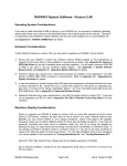
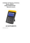
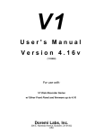
AUDIO DECK
1
2
AES
WORD
MADI
INTERNAL
Audio Deck Manual
Version 2.0
Part# 840-06267-02 Rev b
Publish date: August 1999
Euphonix Inc. 220 Portage Avenue Palo Alto , CA 94306
Tel: (650)855-0400 Fax: (650) 855-0410 Web Page: www.euphonix.com
In the interest of continued product development, Euphonix reserves the right to make improvements in this
manual and the product it describes at any time, without notice or obligation.
R-1, Audio Deck, Studio Hub are trademarks of Euphonix Inc.
©1999 Euphonix Inc. All rights reserved worldwide. No part of this publication may be reproduced,
transmitted, transcribed, stored in a retrieval system, or translated into any language in any form by any
means without written permission of Euphonix Inc.
AD
801
This page intentionally left blank
R-1 Audio Deck Manual
©1999 Euphonix, Inc.
Page 2
TABLE OF CONTENTS
AUDIO DECK ............................................................................................ 4
Component Overview ................................................................................................ 4
Physical Specifications ............................................................................................. 5
Physical Specifications ............................................................................................. 6
Front Panel ........................................................................................................................................... 6
Rear Panel Connectors ....................................................................................................................... 7
Technical Specifications ........................................................................................... 8
Performance Specifications ............................................................................................................... 8
Environmental Requirements............................................................................................................. 8
Power Requirements ........................................................................................................................... 8
Power Cord Plug Configuration ......................................................................................................... 8
Synchronization ......................................................................................................... 9
Sample Rate ......................................................................................................................................... 9
Current Time Position ......................................................................................................................... 9
MADI .......................................................................................................................... 10
SCSI........................................................................................................................... 11
Approved Real-time Drives and Hardware...................................................................................... 11
Drive Tray Configuration with IBM Drives ...................................................................................... 12
Back up & Drive Expansion.............................................................................................................. 12
Back up & Drive Expansion.............................................................................................................. 13
SPECIAL OPERATING PRECAUTIONS .................................................................. 14
Do Not Remove Drives without Closing Media .............................................................................. 14
There Must Always Be A Drive in Audio Deck #1 at SCSI ID #1 ................................................... 14
External SCSI Port Is Restricted ...................................................................................................... 14
Both Drive Bays Should Be Full....................................................................................................... 14
Do Not Change Drive Addresses ..................................................................................................... 15
Setup (Standard R-1 Configuration) ....................................................................... 16
Power Up Sequence................................................................................................. 16
R-1 Audio Deck Manual
©1999 Euphonix, Inc.
Page 3
AUDIO DECK
Component Overview
The Audio Deck is a processing sub-system that moves digital audio data between
SCSI storage devices and MADI (Multi-channel Audio Digital Interface) signal ports.
In essence, this R-1 module converts data transmitted and received in bursts
(packets) from storage devices into evenly clocked synchronized streams of digital
audio.
The Audio Deck uses a control processor to know when and what to record or
play. This control system communicates with the Pilot Computer for information
about stored settings, audio event schedules, and user input. The communication
path for such control data is IEEE 1394. This control path is also designed to allow
the Audio Deck to move actual audio data to and from the Pilot Computer, where
the R-1 system can be attached to a network (including machines of various
operating systems) or to other storage devices formatted for the Windows operating
system. R-1 release 1.0 software, however, does not include audio data
transmission features.
The Audio Deck includes a complete Transport Engine. Not only does the deck
convert SCSI to and from MADI, but the deck provides the mechanisms for this
process to be controlled in very much the same way as a conventional tape machine
even while doing things that a conventional tape machine cannot begin to do, such
as Locate instantly to any Cue. Some features of the Transport Engine.
•
4 SHARC DSPs
•
Same-track real-time punch and edit crossfades
•
24 tracks of playback or recording from a single drive
•
24 tracks of playback and simultaneous seamlessly monitored punch in/out from
two drives
•
24 tracks of constant Sample Rate varispeed recording and playback
•
24 tracks of Jogging/Scrubbing transport motion
•
Clickless start and stop of audio playback
The Audio Deck also includes a router and monitoring mixer. The deck provides
basic routing of it’s input MADI channels to its available 24 channels of recording.
This is in addition to any routing of MADI external to the deck. The deck also
provides a monitor mix of its 24 channels of output.
R-1 Audio Deck Manual
©1999 Euphonix, Inc.
Page 4
Audio Deck Functional Block Diagram
1394
DSP Transport Engine
SCSI
MADI
R-1 Audio Deck Manual
©1999 Euphonix, Inc.
Page 5
Physical Specifications
Front Panel
AUDIO DECK
1
2
AES
WORD
MADI
INTERNAL
AD
801
Dimensions
Height
3 ½ inches ,
Width
19 inches
Depth
17 inches D (18.5 inches including connector depth).
Front Panel Indicators
AES
-
Locked to AES Input for Sample Rate
Word
-
Locked to Word Clock Input for Sample Rate
MADI -
Locked to MADI Input for Sample Rate
Internal
Locked to its own internal crystal for Sample Rate
This order of LEDs is the same order in which signals are tested for their
presence. This detection procedure occurs at the time the Audio Deck is powered on
or the R-1 software application is booted. The Audio Deck does not offer manual
selection of the Sample Rate source from its front panel.
THERE ARE NO USER SERVICEABLE PARTS IN THE AUDIO DECK
R-1 Audio Deck Manual
©1999 Euphonix, Inc.
Page 6
Rear Panel Connectors
EXTERNAL SCSI
AD801
IN
OUT 1
OUT 2
MADI I/O
IN
WORD
OUT
AES
SYNC
IEEE1394
IEEE 1394 ports (3) (IEEE 1394) The 1394 high speed communication protocol allows that any port
from any module can be connected to any port on any other module and that the
cables can “star” from one device, or can be daisy chained from device to device. The
recommended 1394 cable configuration for the R-1 Audio Deck is to connect a cable
from any of the three ports on the Audio Deck to any of the three ports on the Pilot
computer.
Word In
(BNC) May be connected to a Word Clock source if Word Clock is the master
Sample Rate clock for the R-1 system. In the standard R-1 configuration where the
Studio Hub is a short distance from the deck, AES is recommended for synchronizing
the Audio Deck. In configurations where the Studio Hub is located remotely, the
Word Clock output from the Studio Hub may be used as the master Sample Rate clock,
and is then provided to this Audio Deck input.
Word Out
(BNC) May be connected to the Word Clock input of a second chained Audio
Deck in a multi-deck R-1 system. When an external Word clock input is present this
connector provides a regenerated version of the input signal. When no external
Sample Rate source is detected this connector outputs the internally generated clock
signal. This later configuration, where the Audio Deck is the clock master, is not a
recommended mode.
AES In
(XLR Female) Connected to one of the Studio Hub’s AES Sync Outputs in the
standard configuration. This is the recommended clock for the Audio Deck where the
Studio Hub is a short distance away.
MADI In
(BNC) In the standard configuration this is connected to the Studio Hub MADI
output #1.
MADI Out 1
(BNC) Connected to the Studio Hub MADI #2 input in the standard
configuration. From 1 to 24 channels represents Audio Decks main channels of disk
playback and input monitoring. Channels 25 and 26, as well as 27 and 28 each
contain stereo monitor mixes, but the 25/26 pair are reduced in signal strength by –
12 dB.
MADI Out 2
(BNC) Same as MADI Out 1. Provided as a built-in Mult. Can be used with
MADI metering.
R-1 Audio Deck Manual
©1999 Euphonix, Inc.
Page 7
External SCSI
(68 pin Wide SCSI Dsub) External connector to internal Audio Deck SCSI chain.
Exabyte back up tape drive connects here. Do not connect additional SCSI drives
here. Active SCSI terminator must be connected at this port if Exabyte is not
connected.
Technical Specifications
Performance Specifications
16 or 24-bit recording to disk and/or 16 or 24-bit playback from disk
24 channel recording or playback @ 48kHz
40 bit floating point DSP
Environmental Requirements
5 to 35 degrees Centigrade.
Power Requirements
110, 220, or 240 VAC, 50 or 60Hz.
Power Cord Plug Configuration
All Audio Deck are shipped with US power cords. It is your responsibility to
attach the proper plug to the end of the cord. The green with yellow stripe wire is to
be used for the ground connection in the plug.
R-1 Audio Deck Manual
©1999 Euphonix, Inc.
Page 8
Synchronization
Sample Rate
The Sample Rate of the Audio Deck is set by one of three external source signals
or internally by means of crystals and associated circuitry. The Sample Rate source
is determined automatically by the presence of signals at the time the Audio Deck is
powered on or by settings in the R-1 software application. The order in which each
external signal is tested for its presence is as follows:
AES
Word
MADI
As soon as a signal is detected it becomes the source for Sample Rate clocking
of the Audio Deck. In the event that none of these signals are present the Audio
Deck will provide an internal clock driven by crystals. The default internal Sample
Rate of the Audio Deck is 48 kHz. This default internal rate can be overridden by
the R-1 software to generate 44.1, 48kHz. As the standard R-1 configuration also
includes a Studio Hub, this software control over internally generated Sample Rate is
not directly user accessible in version 1.0.
Current Time Position
In the standard configuration, the current time of the R-1 system is established
by the Studio Hub, either according to the Studio Hub’s internal time code generator
or according to external time codes provided to the Studio Hub. The R-1
application software sets the Studio Hub as the system time code master by default.
In this configuration the Studio Hub inserts time code information on track 55 and
56 of the MADI stream to the Audio Deck. To make use of this time code the Audio
Deck must have a 1394 connection to the Studio Hub (both Audio Deck and Studio
Hub are attached to the Pilot Computer in the standard configuration).
R-1 Audio Deck Manual
©1999 Euphonix, Inc.
Page 9
MADI
The MADI input channels 1-54 can be mapped under software control to the
available 1-24 channels of recording (and input monitoring) of the Audio Deck. See
the R-1 Operation Manual section on Input Routing. MADI input channels 55 and 56
are used within the R-1 system (when a Audio Deck and Studio Hub are both
present) to convey time code position data.
The MADI output channels 1-28 are hard-mapped as follows.
1-24
Playback / input monitoring channels
25-26 Monitor mix (for ancillary analog outputs). All odd numbered channels
of the 24 channels of playback and input monitoring are summed left and all even
numbered channels of the 24 channels of playback and input monitoring are
summed right and the results of both left and right are attenuated by –12 dB. The
left channel mix is output via MADI channel 25 and the right channel mix is output
via MADI channel 26.
27-28 Monitor mix (for auxiliary digital outputs / digital copy tracks). All odd
numbered channels of the 24 channels of playback and input monitoring are
summed left and all even numbered channels of the 24 channels of playback and
input monitoring are summed right. These mixes are not scaled or attenuated in
any way. The left channel mix is output via MADI channel 27 and the right channel
mix is output via MADI channel 28. As the mixes are not scaled they will clip if full
strength signals are present on all channels. However when two adjacent channels
are soloed the resulting unmodified output goes directly to channels 27 and 28.
This feature allows for digital copies to DAT or other stereo digital devices using the
ancillary digital outputs of Euphonix converters such as the MA-703.
R-1 Audio Deck Manual
©1999 Euphonix, Inc.
Page 10
SCSI
The Audio Deck uses SCSI 3 Ultra Wide storage technology. However, the
addressing scheme is SCSI 2 as the Audio Deck is designed and optimized for seven
devices in addition to the Audio Deck controller. Each Audio Deck is built to
include two Kingston drive trays (receptacles for the Kingston drive carrier). Only
two real-time (random access) drives can be installed – one each for the
corresponding Kingston trays. These devices are always addressed as SCSI #1 and
SCSI #2, and show up as such in the software directories.
Approved Real-time Drives and Hardware
Only one drive is approved for use with the R-1.
Manufacturer: IBM
Series: Ultrastar 9LZX
Model Number: DRVS-09V
IBM part number: 08L8260
Installation manual:
http://www.storage.ibm.com/techsup/hddtech/welcome.htm
You may wish to order additional drive trays for mounting drives that can be
swapped into and out of the R-1 removable drive hardware. Here is the information:
Manufacturer: Kingston Technology Company, Fountain Valley, CA USA
Family & Series: Kingston Data Express - DE100 series
Drive Carrier only: DE100i-CSWU2/B
Blank Plug: DX100-PLUG
Installation guide:
http://www.storcase.com/install/100swcu2_a.pdf
Drive trays can also be ordered from Euphonix.
R-1 Audio Deck Manual
©1999 Euphonix, Inc.
Page 11
Drive Tray Configuration with IBM Drives
White Molex power
connector
Do not connect ID lines to
these connectors
Yellow ribbon cable
connector
Serial
Number tag
IBM drive
configuration
Diagram
R 101
Orange = Id 3
Ident wires must
run under the
Hard drive and
connect to the
Ident pins of the
terminal block.
(First 4 pins )
Red = Id 2
Label
Brown = Id 1
Black = Id 0
Id 3-2-1-0
Autostart shorting block
Term pwr block use white
shorting block
Terminal block
Use dark shorting
block
R-1 Audio Deck Manual
©1999 Euphonix, Inc.
Page 12
Back up & Drive Expansion
The Audio Deck includes a rear panel SCSI connector for adding an Exabyte
Mammoth drive to the SCSI chain. The Mammoth can be purchased from Euphonix
or elsewhere as an externally enclosed desktop unit, or from Euphonix as a rack
mount unit. The following SCSI configurations are typical.
Audio Deck
One or two 9 gig SCSI hard drives only. Uses SCSI ID# 1 and
SCSI ID# 2 of a single SCSI chain. IDs do not travel with the drives. The Audio Deck
(and its Kingston mount) determine the ID# for whatever drive is plugged in.
DX-202 E
Rack mounted expansion bay for adding either one or two
Exabyte Mammoth tape drives (SCSI ID# 0) to each of either one or two Audio
Decks. Each Exabyte installed in the 202e is on a separate SCSI chain. Only the
Exabyte Mammoth can be connected in addition to the Audio Deck’s own real-time
audio drives (at SCSI ID# 1 and SCSI ID# 2) on the Audio Deck’s SCSI chain.
Back up Expansion bays are interconnected via the external hi-density SCSI
connector on the back of each unit. In version 1.0 only a single Exabyte mammoth
tape drive can be connected to the external SCSI 3 connector.
Audio Deck
9 gig SCSI ID 1
9 gig SCSI ID 2
Mammoth Tape ID 0
Mammoth Tape ID 0
DX202E
DX-202
Rack mounted expansion bay for adding two SCSI drives to Pilot
Computer SCSI chain. Not available in version 3.0. When implemented, these two
drives will reside on a single SCSI chain.
DX202
9 gig SCSI ID 3
R-1 Audio Deck Manual
9 gig SCSI ID 4
©1999 Euphonix, Inc.
Page 13
SPECIAL OPERATING PRECAUTIONS
Do Not Remove Drives without Closing Media
To preserve data integrity in your R-1 system, DO NOT REMOVE AUDIO DRIVES
while the R-1 has a Title loaded, and particularly not when the transport is in Play.
Removing drives while stopped, but without first closing the Title will cause the R-1
to try to access drives that are not there. If you have completely swapped out the
drives, there is the potential that the data intended for one drive could be written
to the wrong drive resulting in data corruption. The R-1 DOES have mechanisms to
try to recognize unexpected drive removals, and the R-1 will attempt to gracefully
notify you that the media has accidentally been dis-mounted or replaced. However,
it is not recommended that the media be removed in such a fashion. Doing so may
jeopardize data integrity.
The Audio Deck loads its drive information when the R-1 application is booted or
when the Media Open command is used on the Remote or when Disk or Tape Media is
selected in the Audio Browser of the Directory Panel then the Load command is
issued. Media Close and Media Unload should be used when media is be dismounted
and not reloaded. For instructions on these operations see the R-1 Operation
Manual in the section called File Management.
Please note that starting the R-1 application will always load all media and reset
the decks. Reseting a deck will also load the SCSI media, so switching to 96kHz
operation (which changes the code running on the deck) will also reload all media.
There Must Always Be A Drive in Audio Deck #1 at SCSI ID #1
Title information is always saved to drive one (SCSI ID #1) on the first Audio
Deck when any Title is saved. There must be a drive installed at SCSI ID #1 for Title
saving to work properly. This target drive may be changed if a problem occurs or if
a Title was created on a higher numbered drive on a different system. This change
of the Title drive is NOT recommended for anything but very specific operations and
should be changed back immediately. See the R-1 Operation Manual for details on
this parameter.
External SCSI Port Is Restricted
The R-1 Audio Deck supports the attachment of an Exabyte Mammoth drive on
the external SCSI connector in the upper right of the rear panel. This is the only
approved device for attachment to this connector. DO NOT ATTACH ADDITIONAL
HARD DRIVES TO THE EXTERNAL SCSI CONNECTOR.
Both Drive Bays Should Be Full
The Audio Deck should not be powered on with a drive bay empty. Each Kingston
tray should be populated with a drive or a Kingston cover-plug to ensure that the air
circulation within the Audio Deck is according to design.
R-1 Audio Deck Manual
©1999 Euphonix, Inc.
Page 14
Do Not Change Drive Addresses
The small screwdriver packaged with the software and documentation is for the
Kingston drive receiver frame on your R-1 Audio Deck. With this screwdriver it is
possible to change the SCSI addresses for the drives loaded into that frame.
However, the changing of SCSI addresses is NOT RECOMMENDED.
R-1 Audio Deck Manual
©1999 Euphonix, Inc.
Page 15
Setup (Standard R-1 Configuration)
The Audio Deck is recommended for the third position in the rack after the
Studio Hub (top of rack) and Pilot Computer (second in rack - below Studio Hub).
•
Attach the provided IEC compatible power cable to the IEC inlet. Attach other
end to wall outlet with appropriate plug adapter if necessary. The Audio Deck
power supply will automatically set itself to work with the voltage in your
country (110, 220, or 240). DO NOT POWER up unit at this time.
•
Attach the provided Red BNC Coax cable from the Studio Hub MADI #1 Output to
the Audio Deck MADI Input.
•
Attach the provided Red BNC Coax cable from the Audio Deck MADI Output 1 to
the Studio Hub MADI #2 Input.
•
Attach the provided yellow XLR cable from the Audio Deck AES Sync In connector
to one of the Studio Hub’s AES Sync Out connectors.
•
Attach the provided green 1394 cables from any of the three 1394 connectors on
the Audio Deck to any of the three 1394 connectors on the Pilot Computer.
Power Up Sequence
The R-1 modules can be powered up in almost any sequence. We suggest that
you monitor the LEDs on the front panels at power up to insure that the intended
settings are in effect.
We recommend that the Audio Deck is booted up third in the R-1 system after
the Studio Hub and the Pilot computer.
Wait about 10 seconds for the Audio Deck to boot fully. The drive ID indicator
lights will stop flashing when the Audio Deck is ready. The AES LED should light
steadily, indicating that the Audio Deck is receiving the Sample Rate Source from
the Studio Hub.
R-1 Audio Deck Manual
©1999 Euphonix, Inc.
Page 16