1
Apex
DIGITAL AUDIO ROUTER
Release Notes
SOFTWARE VERSION 3.0
071842601
DECEMBER 2008
Contacting Grass Valley
International
France +800 8080 2020 or +33 1 48 25 20 20 United States/Canada
Support Centers 24 x 7 +800 8080 2020 or +33 1 48 25 20 20
24 x 7
Asia
+1 800 547 8949 or +1 530 478 4148
Hong Kong, Taiwan, Korea, Macau: +852 2531 3058 Indian Subcontinent: +91 22 24933476
Southeast Asia/Malaysia: +603 7805 3884 Southeast Asia/Singapore: +65 6379 1313
China: +861 0660 159 450 Japan: +81 3 5484 6868
Local Support
Australia and New Zealand: +61 1300 721 495
Central/South America: +55 11 5509 3443
Centers
(available
Middle East: +971 4 299 64 40 Near East and Africa: +800 8080 2020 or +33 1 48 25 20 20
during normal
Belarus, Russia, Tadzikistan, Ukraine, Uzbekistan: +7 095 2580924 225 Switzerland: +41 1 487 80 02
business hours)
S. Europe/Italy-Roma: +39 06 87 20 35 28 -Milan: +39 02 48 41 46 58 S. Europe/Spain: +34 91 512 03 50
Europe
Benelux/Belgium: +32 (0) 2 334 90 30 Benelux/Netherlands: +31 (0) 35 62 38 42 1 N. Europe: +45 45 96 88 70
Germany, Austria, Eastern Europe: +49 6150 104 444 UK, Ireland, Israel: +44 118 923 0499
Copyright © Thomson. All rights reserved.
This product may be covered by one or more U.S. and foreign patents.
Grass Valley Web Site
The www.thomsongrassvalley.com web site offers the following:
Online User Documentation — Current versions of product catalogs, brochures,
data sheets, ordering guides, planning guides, manuals, and release notes
in .pdf format can be downloaded.
FAQ Database — Solutions to problems and troubleshooting efforts can be
found by searching our Frequently Asked Questions (FAQ) database.
Software Downloads — Download software updates, drivers, and patches.
2
Apex — Release Notes
Contents
Applicability . . . . . . . . . . . . . . . . . . . . . . . . . . . . . . . . . . . . . . . . . . . . . . . . . . . . . . . . . . 5
Purpose . . . . . . . . . . . . . . . . . . . . . . . . . . . . . . . . . . . . . . . . . . . . . . . . . . . . . . . . . . . . . . . 5
Materials Supplied . . . . . . . . . . . . . . . . . . . . . . . . . . . . . . . . . . . . . . . . . . . . . . . . . . . . . 6
Upgrade Details. . . . . . . . . . . . . . . . . . . . . . . . . . . . . . . . . . . . . . . . . . . . . . . . . . . . . . . . 7
1024 X 1024 Expansion . . . . . . . . . . . . . . . . . . . . . . . . . . . . . . . . . . . . . . . . . . . . . . . . 7
Standard Apex Models . . . . . . . . . . . . . . . . . . . . . . . . . . . . . . . . . . . . . . . . . . . . . . 7
Notes . . . . . . . . . . . . . . . . . . . . . . . . . . . . . . . . . . . . . . . . . . . . . . . . . . . . . . . . . . . . . 7
MADI Support (Standard Apex Only) . . . . . . . . . . . . . . . . . . . . . . . . . . . . . . . . . . 11
Fiber Extenders (Standard Apex Only) . . . . . . . . . . . . . . . . . . . . . . . . . . . . . . . . . 12
Fiber Extender Installation . . . . . . . . . . . . . . . . . . . . . . . . . . . . . . . . . . . . . . . . . . 14
CX-34000 Control Crosspoint Board Configuration. . . . . . . . . . . . . . . . . . . . . . . 16
S34-1/2 - Stereo/Mono Mode Selection . . . . . . . . . . . . . . . . . . . . . . . . . . . . . . . 16
S34-8 - Enable Reference/V-fade Master Setting . . . . . . . . . . . . . . . . . . . . . . . 16
S28 5-6 - AES/Video Reference Selection. . . . . . . . . . . . . . . . . . . . . . . . . . . . . . 18
S28 7-8 - V-fade. . . . . . . . . . . . . . . . . . . . . . . . . . . . . . . . . . . . . . . . . . . . . . . . . . . . 18
S30 7-8 MADI AES/Video Reference Settings. . . . . . . . . . . . . . . . . . . . . . . . . . 18
Output Card Switches . . . . . . . . . . . . . . . . . . . . . . . . . . . . . . . . . . . . . . . . . . . . . . 19
Input Card Switches . . . . . . . . . . . . . . . . . . . . . . . . . . . . . . . . . . . . . . . . . . . . . . . 19
S31 (LIN NUM / VREF) . . . . . . . . . . . . . . . . . . . . . . . . . . . . . . . . . . . . . . . . . . . . 19
S32 (SR AREF/VREF) . . . . . . . . . . . . . . . . . . . . . . . . . . . . . . . . . . . . . . . . . . . . . . 19
AES/Video Reference Notes . . . . . . . . . . . . . . . . . . . . . . . . . . . . . . . . . . . . . . . . 19
V-fade (Silent Switching) (Standard Apex Only) . . . . . . . . . . . . . . . . . . . . . . . 20
Upgrade Procedure. . . . . . . . . . . . . . . . . . . . . . . . . . . . . . . . . . . . . . . . . . . . . . . . . . . . 21
For All Systems Receiving Version 3 Upgrade . . . . . . . . . . . . . . . . . . . . . . . . . . . 21
Apex — Release Notes
3
Contents
4
Apex — Release Notes
Version
3.0
DECEMBER 2008
Apex Release Notes
Applicability
This release applies to standard Apex Digital Audio Router units only. It
does not apply to Apex Plus systems.
Purpose
The primary purpose of this firmware (gateware) release is to provide the
following for Standard Apex systems:
•
1024 x 1024 support (page 7).
•
MADI support – Input cards can now accept both AES and MADI formatted audio and the output cards stream both AES and MADI formatted audio (page 11).
•
Remote frame location (up to 5 km) using Apex Fiber Extenders
(page 12)
•
Redundant CX-34000 Control Crosspoint board support (page 16)
•
V-Fade support – provides click-less switching of AES signals
(page 20).
•
Lock to video reference – allows users to synchronize audio switching
to NTSC or PAL.
•
Dolby E support - switching of Dolby E signals is now aligned properly
resulting in clickless switching.
For a detailed list of problems fixed and known limitations, see Apex
Release Notes Addendum, Release 3.0, part number 071842701.
Apex — Release Notes
5
Version 3.0
Materials Supplied
The materials supplied for this release are given in Table 1.
Table 1. Materials Supplied With This Release
Qty
1 per frame
Description
Part Number
License Configuration Board
Depends on Frame Type*
1
Release Notes
071842601
1
Release Notes Addendum
071842701
* License Boards vary according to the rear panel main connector type
(75 or 110 ohm). Refer to Table 2.
Table 2. Apex License (Configuration) Boards
Nomenclature
Description
U2 Firmware Part Number
APX-CL-34075
Apex 75 ohm License board
080835403
APX-CL-34110
Apex 110 ohm License board
080835503
These items are obtained through Technical Support. For contact information, see page 2.
6
Apex — Release Notes
Upgrade Details
Upgrade Details
1024 X 1024 Expansion
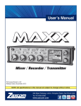
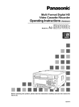
Refer to Figure 1 on page 8 for an illustration of the Apex frame module
locations (no front door installed).
Standard Apex Models
With this release, five Standard Apex 256 x 256 frames can be connected to
form 1024 x 1024 systems. The frames are connected by four-meter (13-foot)
InfiniBand cables.
Figure 3 on page 10 shows a fully expanded (1024 x 1024) system with 6
InfiniBand expansion cables. Smaller systems will require fewer cables (see
Table 3 on page 10); the connector numbering scheme remains the same as
that shown for the large system. Each group of four Expansion (InfiniBand)
connectors correspond to one MX-34000 Matrix board.
In addition to the InfiniBand cables, expanded Apex systems with more
than one chassis require RG-59 Master Clock connections. The three Master
Clock Out connectors are functionally identical, i.e., they can be connected
to any chassis. See Figure 4 on page 10. As shown in Figure 2 on page 9,
each group of four Master Clock BNC connectors correspond to a Matrix
board.
If two or more frames of a multi-frame standard Apex system must be
located more than four meters apart, 2 each model APX-FBR-EXT Apex
Fiber Extenders must be ordered for each remote chassis. For more information, see page 12.
Notes
Redundant InfiniBand cables (not shown in the drawings) can be added if
each chassis is equipped with a secondary matrix board. In this case the
Expansion B connectors shown in Figure 2 on page 9 would be used.
Only one CX-34000 Control Crosspoint board is needed per system, regardless of expansion.
Apex — Release Notes
7
Version 3.0
Figure 1. Apex Digital Audio Router, Showing Standard-type 75 and 110 Ohm Rear Panels
8
Apex — Release Notes
E
X
P
A
Apex — Release Notes
OUT
OUT
MC A
LOW EST
1
IN
2
3
OP MON A
EXPANSION
256
512 768
1024
1280
1536
1792
2048
AES REF A
HIGH EST
4
VID REF A
E
X
P
B
OUT
OUT
MC B
LOW EST
1
IN
2
3
OP MON B
EXPANSIO N
AES REF B
HIGH EST
4
VID REF B
Upgrade Details
Figure 2. Auxiliary Panel
9
Version 3.0
Figure 3. Standard Apex Expansion InfiniBand Cabling (optional redundant cables not shown)
Chassis 0
Inputs 1-256
1024 x 1024
Expansion connector
1 2 3 4
Chassis 1
2 Expansion
connector
3
Expansion 3
connector 2
Inputs 257-512
Chassis 3
1
1
4
4
Inputs 769-1024
2
1 3
4
Expansion connector
Chassis 2
Inputs 513-768
Figure 4. Standard Apex Expansion Master Clock Cabling (optional redundant cables not shown)
Chassis 0
Inputs 1-256
1024 x 1024
Out Out Out In
Chassis 1
Inputs 257-512
Out
In
Chassis 4
Out
Out
Out
Out
Out
In
In
Inputs 769-1024
Out Out Out
Chassis 2
Inputs 513-768
Table 3. Standard Apex InfiniBand and Master Clock Cable Requirements
InfiniBand cables needed
10
Master Clock cables needed
Switcher size
# of Chassis
Non-redundant
(1 Matrix board per chassis)
Redundant
(2 Matrix boards per chassis)
Non-redundant
(1 Matrix board per chassis)
Redundant
(2 Matrix boards per chassis)
256 x 256
1
0
0
0
0
512 x 512
2
1
2
1
2
768 x 768
3
3
6
2
4
1024 x 1024
4
6
12
3
6
Apex — Release Notes
Upgrade Details
MADI Support (Standard Apex Only)
Standard Apex I/O boards are presently supplied with a BNC MADI hardware port. With this release, the MADI port operates as follows:
Apex — Release Notes
•
When a MADI signal is connected to an input board, signals arriving on
the other input connectors are ignored.
•
The signal present at the MADI connector on an output board consists
of a multiplexed stream of all 64 channels (32 pairs) on the board. All 32
pairs will also be present on the corresponding 75 ohm (or 110 ohm)
connectors.
•
The input cards’ reference can be switched to match the input MADI
reference via the configuration switches on the Control Crosspoint
Board. See Figure 8 on page 17.
11
Version 3.0
Fiber Extenders (Standard Apex Only)
If two or more frames of a multi-frame standard Apex system must be
located more than four meters apart, 2 each model APX-FBR-EXT Apex
Fiber Extenders must be installed for each remote chassis. For example, if
four frames were in one equipment rack and a fifth frame was located in
another room, then two extenders would be needed. See Figure 6 on
page 13.
Two lengths of fiber optic cable are available: 300 meters (984 feet) and 5000
meters (16,400 feet or 3.1 miles). If the 300 meter cables are used, then the
Fiber Extenders should be ordered with APX-SFP-M300 small form-factor
plug-in multi-mode transceivers; if 5 km cables are used, then
APX-SFPS5000 small form-factor plug-in single-mode transceivers should
be ordered. Each optical cable pair requires two transceivers (which are
plugged into the Fiber Extender ports). In the example shown in Figure 6
on page 13, a total of 16 transceivers would be needed; i.e., one transceiver
for each end of each fiber optic cable pair. If redundant cables were
installed, a total of 32 transceivers would be needed for this system.
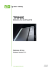
Each Fiber Extender is 1 RU high, approximately 12 inches (30 mm) deep,
and includes I/O ports for fiber optic cable connection to the remote
module and InfiniBand ports for connection to a local frame. Each module
also includes redundant power supplies and all rear panel ports needed for
redundant cabling. See Figure 5.
Note
Master Clock cabling is not required for the remote frame(s) connected using
fiber extenders. The clock signal is recovered internally in this application.
Figure 5. Apex Fiber Extender
12
Apex — Release Notes
Upgrade Details
Figure 6. Example of Standard Apex Expansion InfiniBand Cabling with Fiber Extenders
Chassis 0
Inputs 1-256
Expansion connector
1 2 3 4
1024 x 1024
InfiniBand cable
T
1 2 3 4
TT TT TT TT
Transceiver
Fiber optic cable pair
(SFP transceivers required)
T
Fiber Extender
5 km max.
Transceiver
TT TT TT TT
1 2 3 4
Chassis 1
Expansion
connector
Inputs 257-512
Fiber Extender
Chassis 3
1
1
3
2
2
3
Expansion
connector
4
4
Inputs 769-1024
2
1 3 4
Expansion connector
Chassis 2
Inputs 513-768
Apex — Release Notes
13
Version 3.0
Fiber Extender Installation
Rack Mounting
The Apex Fiber Extender is mounted in a standard 483 mm (19-inch) rack.
Rear frame support is not required. Position the unit in the rack and secure
the panel in place using rack screws or bolts and nuts (depending on your
equipment rack type). Cooling is provided by an internal fan and vent
opening located on the sides of the unit; these areas must be kept clear of
obstructions.
Special Safety Considerations for Rack Mounting
•
Elevated Operating Ambient – If installed in a closed or multi-unit rack
assembly, the operating ambient temperature of the rack environment may be greater than room ambient. Therefore, consideration
should be given to installing the equipment in an environment compatible with the maximum specified ambient temperature of 55
degrees C (130 degrees F).
•
Reduced Air Flow – Installation of the equipment in a rack should be
such that the amount of air flow required for safe operation of the
equipment is not compromised.
•
Mechanical Loading – Mounting of the equipment in the rack should
be such that a hazardous condition is not achieved due to uneven
mechanical loading.
Power Supplies
Where possible, the two power supply cords should be connected to independent power sources. The supplies are auto sensing from 110 VAC to 240
VAC; power consumption is 30 Watts when fully populated with 16 SFP
transceivers.
Special Safety Considerations for Power Connections
•
Circuit Overloading – Consideration should be given to the connection
of the equipment to the supply circuit and the effect that overloading of the circuits might have on overcurrent protection and
supply wiring. Appropriate consideration of equipment nameplate
ratings should be used when addressing this concern.
•
14
Reliable Earthing – Reliable earthing of rack-mounted equipment
should be maintained. Particular attention should be given to
supply connections other than direct connections to the branch
circuit (e.g. use of power strips).
Apex — Release Notes
Upgrade Details
Cabling
Figure 7 shows the cabling details between a remote chassis (Chassis 0) and
a local chassis (Chassis 1) Each chassis is connected to an adjacent Fiber
Extender using an InfiniBand cable. The extenders are connected using two
fiber optic cables, each of which is actually a pair of cables. In this case a
total of four transceivers are installed, i.e., two transceivers in each Fiber
Extender. Each transceiver is installed label up in the appropriate slot on
the rear panel by sliding the transceiver inward until it locks in place. The
protective black plug is then removed to allow insertion of the fiber cable
connector. Note that the protective white covers must be removed from the
cables before they can be connected; to remove the covers, press the blue
tab marked B and A. The wire locking bail on the transceiver must be in the
up position when the connector is inserted.
Redundant (Expansion B) cables are not shown in this example but are connected in a similar manner.
Figure 7. Examples of Connections Between Local and Remote Chassis
Chassis 0
Inputs 1-256
Expansion connector
1
Infiniband cable
Remote Fiber Extemder
Fiber optic cable pair
Fiber optic cable pair
5 km max.
Local Fiber Extemder
Chassis 1
1
Infiniband cable
Expansion
connector
Inputs 257-512
Apex — Release Notes
15
Version 3.0
CX-34000 Control Crosspoint Board Configuration
This release affects the manner in which the CX-34000 DIP switches are set.
For the following discussion, please refer to Figure 8 on page 17.
S34-1/2 - Stereo/Mono Mode Selection
The Apex is normally operated in two-level stereo mode (both switches
OFF). This mode, which is also referred to as split stereo, allows for stereo
mode switching such as mix, reverse, etc. In this mode the Apex boards are
programmed so that the right channel is always 4 physical level numbers
higher than the left channel.
With S34-1 ON and S34-2 OFF, the switcher will operate as one physical level,
which is considered standard AES mode. This mode is also referred to as
locked stereo.
Note
Locked stereo mode does not apply to Encore-controlled systems.
With S34-2 ON, the switcher will operate in Mono mode. In this case a
256 x 256 router is configured as a 512 x 512 mono router.
S34-8 - Enable Reference/V-fade Master Setting
Standard Apex
If S34-8 is ON:
•
The reference and V-fade settings for chassis 0 output card 0 (S28 5-8)
will apply to all output boards, and
•
The reference settings for chassis 0 input card 0 (S30 7-8) will apply to
all input boards, i.e., the settings will apply to all MADI inputs.
If S34-8 is OFF, REF and V-fade can be set on a board-by-board basis using
switches S1 through S30 as described below.
Apex Plus
S34-8 must be ON for Apex Plus:
•
16
The reference settings for chassis 0 output card 0 (S28 5-6) will apply to
all output boards.
Apex — Release Notes
Upgrade Details
Figure 8. DIP Switch Settings on CX-34000 Crosspoint Board
On
2-level stereo mode =
AES ("locked") mode =
Mono mode =
= Standard Apex: Enable all “Output Card”
switches and all “Input Card” (MADI) switches.
= Apply settings of S28 5-8 to all “Output cards” and
apply settings of S30 7-8 to all “Input cards” (MADI).
Apex Plus must use this setting.
Mono mode =
OUTPUT CARDS
INPUT CARDS (MADI)
AES REF B
V-fade Off
VID REF B
V-fade Off
AES REF A
V-fade Force On*
(not recommended)
VID REF A
V-fade Auto*
---- MADI ----
Standard Apex only: If S34-8 is set to OFF,
REF and VFADE can be set on a card-by-card basis.
S28
If S34-8 is set to ON, settings for Chassis 0
Output Card 0 (S28 5-8) will apply to all “Output
Cards”, and settings for Chassis 0 Input Card 0
(S30 7-8) will apply to all “Input Cards” (MADI).
On
S30
On
AES REF B
VID REF B
AES REF A
VID REF A
*Requires a video reference
to be selected for this card.
V-fade not available for Apex Plus.
Apex — Release Notes
17
Version 3.0
S28 5-6 - AES/Video Reference Selection
These settings will be assigned to all output boards when S34-8 is ON. Otherwise, they will apply only to output board zero in chassis zero.
These two switches are used to select Video Reference A, Video
Reference B, AES Reference A, or AES Reference B. For switch setting
details, please refer to Figure 8 on page 17.
For more information about reference settings, see AES/Video Reference
Notes on page 19.
S28 7-8 - V-fade
Standard Apex
These settings will be assigned to all output boards when S34-8 is ON. Otherwise, they will apply only to output board zero in chassis zero.
To enable V-fade in the Auto mode, set S28-7 and S28-8 both to OFF. In this
case, one of the two Video References must be selected on S28 5-6 (as just
described above).
To disable V-fade, set S28-7 to ON. In this case, the position of S28-8 doesn’t
matter.
Note
Use of V-fade in the force on mode (S28-7 OFF and S28-8 ON) is not recommended.
For more information about V-fade, see V-fade (Silent Switching) (Standard
Apex Only) on page 20.
Apex Plus
V-fade is under development. S28-7 must be ON.
S30 7-8 MADI AES/Video Reference Settings
Standard Apex
These settings will be assigned to the MADI inputs of all input boards
when S34-8 is ON. Otherwise, they will apply only to output board zero in
chassis zero.
The switches are used to select Video Reference A, Video Reference B, AES
Reference A, or AES Reference B. For switch setting details, please refer to
the assembly drawing on page 17.
For more information about reference settings, see AES/Video Reference
Notes on page 19.
18
Apex — Release Notes
Upgrade Details
Apex Plus
MADI operation is under development. These switches are not used.
Output Card Switches
•
S1 through S4
•
S7 through S10
•
S13 through S16
•
S19 through S22
•
S25 through S28
These switches, when S34-8 is OFF, can be used to make reference and
Vfade selections on a board-by-board basis. The settings are the same as
those shown for S28 5-8 in Figure 8 on page 17.
Input Card Switches
•
S5 and S6
•
S11 and S12
•
S17 and S18
•
S23 and S24
•
S29 and S30
These switches, when S34-8 is OFF, can be used to select the MADI reference on a board-by-board basis. The settings are the same as those shown
for S30 7-8 in Figure 8 on page 17.
S31 (LIN NUM / VREF)
These switches are not used.
S32 (SR AREF/VREF)
These switches are not used.
AES/Video Reference Notes
If redundant Matrix boards are installed, the same reference must be presented to both REF A and REF B connectors, the system will automatically
operate the Matrix boards as a redundant pair. For more information, refer
to the Apex manual.
Apex — Release Notes
19
Version 3.0
V-fade (Silent Switching) (Standard Apex Only)
The Apex utilizes a silent-switching design to minimize unwanted clicks
and pops. You can turn this feature on or off for each output board (i.e., in
blocks of 32 outputs).
Note
Output boards must be using a Video (not AES) reference to perform V-fades.
The V-fade starts 20 msec before the start of the frame boundary at which
the switch is going to occur. The volume fades down linearly to 0 at the
frame boundary, at which instant the switch occurs (early in line 9), then the
audio volume is faded back up to full volume linearly over the next 20
msec. Since each output card has its own set of V-fade setting DIP switches,
one can enable V-fade on each output card independently. However, all 32
streams on each output card get the same setting.
In Auto mode, V-fade does not occur if the audio stream is compressed
(e.g., Dolby E). This is the reason why the use of V-fade in the force on mode
(S28-7 OFF and S28-8 ON) is not recommended.
20
Apex — Release Notes
Upgrade Procedure
Upgrade Procedure
For All Systems Receiving Version 3 Upgrade
CAUTION The next step will interrupt signals passing through the router.
Note
Customers using this equipment in a continuous 24/7 environment should
consult Technical Support concerning alternate procedures. Possibilities may
include patching around the router during the upgrade.
1. Power down all frames by disconnecting the rear power cords.
2. Remove the installed License board(s) and replace it with the one(s)
provided.
3. Check the CX-34000 Control Crosspoint Board DIP switch settings as
discussed above.
4. Power up the system in frame-number order: frame 0, then frame 1,
then frame 2, etc.
The new firmware will be downloaded automatically from the new
license board to the other boards; the router will then be refreshed by
the control system (i.e., crosspoints will be returned to their state prior
to power off). This process will take from 2 to 30 seconds.
5. This completes the upgrade.
Apex — Release Notes
21
Version 3.0
22
Apex — Release Notes