1
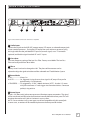
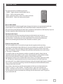
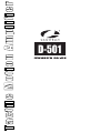
Tactile Motion Amplifier
D-501
IMPORTANT SAFETY INSTRUCTIONS
WARNING:
1. Read and keep these instructions for future reference.
2. Do not use this apparatus near water.
3. Clean only with a dry cloth.
4. Do not block any ventilation openings. Install according to manufacturer’s instructions.
5. Do not install near any heat sources such as radiators, heat registers, stoves or other apparatus
6. Do not override the safety purpose of the polarized or grounding-type plug. A polarized plug has two blades one wider than the other. A grounding type plug has two blades and a third grounding prong. The wide blade
electrician for replacement of the obsolete outlet.
7. Protect the power cord from being walked on or pinched particularly at plug, convenience receptacles, and
the point where it exits from the apparatus.
.
or sold with the apparatus. When a cart is used, use caution when moving the
cart/apparatus combination to avoid injury from tip-over.
,
10. Unplug this apparatus during lightning storms or when unused for long periods of time.
in any way, such as when the power-supply cord or plug is damaged, liquid has been spilled or objects have fallen
into the apparatus, the apparatus has been exposed to rain or moisture, does not operate normally, or has
been dropped.
12. To completely disconnect this equipment from the AC mains, disconnect the power supply cord plug from
the AC receptacle
13. This is CLASS II apparatus with double insulation, and no protective earth provided.
CAUTION
CAUTION: TO REDUCE THE RISK
OF ELECTRICAL SHOCK, DO
NOT REMOVE COVER. NO USER
SERVICEABLE PARTS INSIDE.
REFER SERVICING TO QUALIFIED
SERVICE PERSONNEL.
triangle, is intended to alert the user to the presence of
uninsulated dangerous voltage within the product’s enclosure
shock to persons.
The exclamation point within an equivalent triangle is intended
to alert the user to the presence of important operating
and maintenance (servicing) instructions in the literature
accompanying the appliance.
D-501 Amplifier User’s Manual
i
Ta b l e o f C o n t e n t s
Congratulations ___________________________________________________________1
Product Features ___________________________________________________________1
Front Panel Features________________________________________________________2
Rear Panel Features _______________________________________________________3, 4
Installation ________________________________________________________________5
Operation _________________________________________________________________6
Specifications and Troubleshooting ____________________________________________7
D-501 Amplifier User’s Manual
ii
Congratulations
Congratulations on your purchase of a Crowson D-501 amplifier and Actuators
This system represents the state-of-the-art in low frequency reproduction. Read
and follow the instructions below to ensure safe and proper system operation.
Warning!
To prevent fire or shock hazard, do not expose this equipment to rain or moisture. To avoid
electrical shock, do not open the amplifier enclosure or the chassis cover. Please observe
all warnings on the equipment itself. There are no user serviceable parts inside. Please refer
all service questions to your authorized Crowson or dealer.
Prior to Installation
Please unpack the system carefully. Please save the carton and all packaging materials
for future use. Record the serial number in the space provided on the warranty card and
page 15 of this manual for future reference.
Product Features
D-501 TACTILE MOTION AMPLIFIER
•
•
•
•
•
•
•
•
•
•
•
•
•
500 watts RMS (700 W peak) high efficiency, Class D
High current output easily drives up to four Crowson Actuators
115V or 230V operation
Music and Movie modes
Mute control
Variable intensity control
Line-level (RCA) inputs
Signal sensing auto turn on/off (defeatable)
12 Volt trigger
Selectable phase control (0 or 180 degrees)
Built-in adjustable (40-160 Hz) digital low-pass crossover with 24 dB/octave slope
Blue power indicator LED
Universal IR repeater mini-jack
D-501 Amplifier User’s Manual
1
Front Panel Features
2
7
4
INTENSITY
Tactile Motion Amplifier D-501
1
3
6
5
Figure 1: Front Panel Features of the D-501 amplifier.
(1)
1 Power Switch
This button forces your D-501 amplifier into standby mode. The power LED turns red
and the amplifier puts out no power. The unit will remain in this mode until the POWER button
is pressed again. To fully deactivate (i.e. power down) the unit, use the main power switch on
the back panel.
2 Power LED
(2)
This LED illuminates when the power is on. Blue indicates normal operation. The LED turns
red when the unit is in standby mode or the remote has been used to deactivate the unit,
and dims when the unit is in night mode.
(3)
3 Modes
The Music or Movie toggle button changes the Intensity to an appropriate level for the source material.
LEDs placed above the Music or Movie text on the front panel indicate the mode.
Music and Movie modes both have a flat frequency response. Movie mode has a 6db boost over Music
(4)
4 Remote Eye
This is the eye that receives infrared commands from the supplied remote control.
5 Intensity (Gain) Control
(5)
This continuous rotary knob allows you to balance the output from the motion system with the
output of the main speakers in your audio system. The intensity should be set to achieve a
natural blend between the subwoofer and motion system.
Note: Intensity can also be controlled by using the supplied remote.
WARNING:
Some manufacturers preset their receivers with the Sub-Out (a.k.a. LFE)
channel signal at a minimum level. It is very important to verify that your receiver Sub-Out
channel is set to the same output level as your front right and left channels.
(6)
6 Intensity Level Display
This display shows the intensity setting for several seconds after adjustment. 32 steps.
(6)
7 Optional Rack Mount Ears (Included)
These ears can be attached to the D-501 amp to allow standard 19” rack mounting.
D-501 Amplifier User’s Manual
2
Rear Panel Features
Actuator 1 and 2
7
8
9
10
Actuator 3 and 4
11
Figure 2: Rear Panel Connections of the D-501 amplifier.
(7)
7 Audio Inputs
Connect these jacks to the LINE OUT preamp output, LFE output, or subwoofer output jacks
of your receiver/processor . If using the LFE output from your receiver or processor, plug
the single cable into the jack labeled LFE input or, for more signal, use a “Y” connector
(optional) and feed the signal into both “R” and “L” inputs.
8 Cross-Over
(8)
Crossover frequency setting of the Low Pass Filter. Factory-set at 100Hz. The Low Pass
Filter can be adjusted from 40 to 160Hz.
9 Phase
(9)
Factory-set at 0° and can be changed to 180°. The phase of the actuators can be
adjusted to align the signal coincidence of the subwoofer and Tactile Motion System.
(1
10 Power Modes
a. ON ---------------- Always On
b. AUTO ------------ On, triggered via signal sense; when signal is off, amp will stay on for
approximately 15 to 20 minutes.
c. TRIGGERED ----- On, triggered by 12 VDC, 100mA minimum. NOTE – Use the 1/8˝ mono
mini-jack to connect a 12 volt trigger wire from other devices. Connector
polarity is tip positive.
(1
11 Control Input
Use this 1/8˝ Mono mini-jack to connect to most IR emitter output connections. The signal
will be transferred and flashed to the IR receiver internally behind the front panel. This will
eliminate the need to add “stick-on” emitters in most systems.
NOTE: Due to variations in IR system types, not all are compatible with this control jack.
In some cases, an emitter will be needed to place over the front panel IR window.
D-501 Amplifier User’s Manual
3
Rear Panel Features
Actuator 1 and 2
14
13
12
15
Actuator 3 and 4
18 to 14awg speaker wire
8ohm
Line-Level Mono Signal
from Source (LFE)
Or
Stereo Line-Level
Input from Source
8ohm
1
3
Optional #2 and #4
Actuators are connected
in parallel with #1
and #3 Actuators.
Note: A “Y” connector can
be used as an option.
2
8ohm
4
8ohm
Figure 2: Line-Level and Speaker Level Connections.
(1
12 Outputs
Actuator Connection 5-way Binding Post Terminals. Connect the output terminals to the Actuators
being controlled by the D-501 amplifier. Connect a max of two Crowson 8ohm Actuators to each
red/black pair of output terminals.
Caution!!! To avoid damage to your D-501 amp and Actuators, be sure to maintain correct
polarity when making all speaker connections; red (positive) to red, and black (negative)to
black. Be sure that all connections are tight, and that there are no loose strands or frayed wires.
Caution!!! The output is a push-pull design, do not ground the negative.
13 Voltage Selector
(1
Input voltage setting selects the appropriate 115V or 230V setting. The 115V position of this
switch is correct for North America; most other regions require setting it to 230V. Make sure
the 115/230V switch is set for the correct AC line (mains) voltage before you connect the D-501’s
power cord. THE D-501 MAY BE SERIOUSLY DAMAGED IF THIS SWITCH IS SET INCORRECTLY.
(1
14 Power Switch
Master Power ON/OFF power switch for the amplifier.
(1
15 IEC Power Cord Socket
D-501 Amplifier User’s Manual
4
Installation
Rackmount Installation
1. Remove the amplifie’s four feet from the bottom of the chassis.
2. Attach the included rack-mount ears to the front sides of the amplifier chassis.
3. Securely mount the amplifier into the 19” equipment rack. The amplifier will
occupy 1U of rack space.
4. For best results leave 1U of room for ventilation between amplifiers.
Ventilation
Be sure that the amplifier is in a well-ventilated area that provides adequate cooling.
If your installation lacks good air flow, such as cabinets or wall-mounted racks, it may
be necessary to create some ventilation to air outside the cabinet or rack.
Do not block ventilation holes, or impede air flow by placing objects on or around
the amplifier. Do not place the amplifier on carpeting or any similar material.
Do not install the amplifier near a source of heat, or in an extremely humid or wet location.
Positioning
If your D-501 is not rack mounted, position it with all feet resting on a solid level surface.
Make sure that there is a minimum of 2” of free air space above the amplifier and 2”
on each side for proper ventilation. Allow a minimum of 3” of depth behind unit to
accommodate cables and connectors.
CAUTION: All connections and switching must be done with the amplifie’s power switch
positioned to ‘Off’. Connect the power cord last to be sure that the amplifier is off during
all of your connections and set up.
Interconnect Cables
When connecting the D-501 amplifier to your Actuators using the speaker level connections,
use a high quality speaker cable. It is recommended that you keep the length of cable as short
as possible to avoid any potential external interference problems. When connecting the D-500
amplifier to your actuators, use speaker cable that is at least 18-gauge. Be very careful
to avoid any loose or frayed strands that could result in a short, causing a dangerous condition
and possible damage to your unit. Cables of extremely large size are typically not required.
Extremely large wire may not properly fit in thebinding posts, resulting in a poor connection and
possible short circuits.
Caution! The power cord should be routed in such a way that it will not be walked on, pinched
or compressed in any way that could result in damaging the insulation or wire.
D-501 Amplifier User’s Manual
5
operation
The remote control has the following functions:
1. POWER - Toggles between Standby Mode and ON.
2. VOL+/- – Adjusts the Intensity (level).
3. MUTE – Mutes the motion system. Press again to unmute.
4. MUSIC/MOVIE – Selects the corresponding mode.
Music or Movie Mode
The front panel Music or Movie toggle button changes the intensity to an appropriate level for the
source material. You can alternitively use the hand-held remote to select Movie or Music.
LEDs on the front panel indicate the mode. Music and Movie mode both have a flat frequency response.
The Movie mode has 6dB of additional gain for added impact.
Intensity (Level) Control
Adjust the intensity of motion by turning the intensity knob clockwise to increase, or
counter-clockwise to decrease. The knob on the front panel is a continuous rotary control
with 32 positions. Set the intensity to your preferred level. The intensity should be set to
achieve a natural feeling blend between the subwoofer and motion system.
About Low-Pass Filter (LPF)
The D-501 amplifier inputs sum the left and right channels together and the resulting
signal is passed through an adjustable low-pass crossover before being amplified. The crossover
control allows you to adjust the upper limit of the Actuator’s frequency response from 40 to
160 Hz. The Actuator’s response will begin rolling off above the frequency you set this control
to. The slope is 24 dB/octave.
You should set the crossover frequency to obtain a smooth and seamless blend with the
subwoofer and the main speakers in your system. Adjusting the LPF to the preferred setting
will ensure that desirable low-frequency motion is present, while undesirable
high-frequency content (such as motion from human voices) is not. Proper adjustment of the
LPF will allow your motion experience to most closely resemble a real-world experience.
Start with the LPF set to 100Hz. Reduce the frequency setting if unwanted high frequency content
such as voices is present during testing. Increase the setting if you feel that desirable content
is being unnecessarily removed.
Most receivers and processors provide a menu option in which you can characterize main
speakers as “large” or “small” speakers. This affects the bass signals passed to the main
speakers. We recommend in most cases setting the main speakers to “small,” despite their
size and frequency response characteristics, allowing all multi-channel bass and LFE signals to
be passed to the D-501.
D-501 Amplifier User’s Manual
6
Specifications and troubleshooting
Specifications
Continuous Power Output
312 watts RMS powering 2 Actuators (8 ohms ea)
500 watts RMS powering 4 Actuators (8 ohms ea)
Input Sensitivity
200 mv for full output, 500 watts, with level control set to 32 (max).
Frequency Response
10 - 160 Hz
Distortion
.04% THD+N 1W/2W 100 Hz
Auto On Sensitivity
3 mv
External Trigger Voltage
5 V - 20 V
Movie/Music Modes
Music: Flat
Movie: Flat, +6dB
Dimensions
17˝ W (18.9˝ including rack mounts)
1.7˝ H (1.9˝ including feet)
10.4˝ D (11.2˝ including speaker connections)
Weight
19.7 lbs.
CE safety certified
Trouble Shooting
Crowson dealer or Crowson technical support at 888-427-6976.
into an outlet that does not have power. Check connections and
verify power at the outlet.
No audio output
• Audio cable to the source component is not connected properly,
connected to output or the cable is defective. Check connections
• Check the connections of the speaker wire at both the speaker
• The level adjustment is turned down. Turn it to the right slowly to
raise the volume.
Hum or buzzing
sound is heard
not turn on
• Check RCA input cables by removing them one at a time (powering
connection or cable is to blame.
• The Power Switch on the front panel must be on.
• The Power Mode switch may be set to the wrong mode for your system.
Warranty
2-Year Limited Warranty
Crowson
components found to be defective in material or workmanship under normal conditions of use. This warranty shall
Crowson Technology
authorization number (RA).
D-501 Amplifier User’s Manual
7