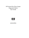
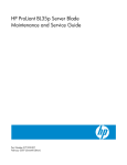
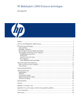
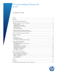
1
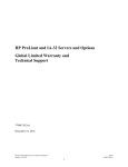
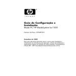
The HP BladeSystem p-Class 1U power enclosure: hot-plug,
redundant power for a server blade enclosure
technology brief
Abstract.............................................................................................................................................. 3
Introduction......................................................................................................................................... 3
Components of the enclosure ................................................................................................................ 3
Hot-plug, redundant power supplies ................................................................................................... 3
Redundant AC power ....................................................................................................................... 4
Hot-plug power management module ................................................................................................. 5
Features of the enclosure ...................................................................................................................... 5
Bi-directional electronic e-fuse ............................................................................................................ 5
Power zones.................................................................................................................................... 5
Firmware in mixed environments .................................................................................................... 6
Dynamic power saver....................................................................................................................... 7
Redundancy with dynamic power saver .......................................................................................... 7
Enabling dynamic power saver ...................................................................................................... 8
Serial port ....................................................................................................................................... 8
Remote access to the serial port ................................................................................................... 10
Efficient cabling ............................................................................................................................. 10
Management link cable............................................................................................................... 11
Power distribution unit cables....................................................................................................... 11
Infrastructure configurations ................................................................................................................ 12
Using PDUs with the 1U power enclosure.......................................................................................... 13
Redundancy............................................................................................................................... 13
Maximum rated VA capacity ....................................................................................................... 13
Number of PDU outlets................................................................................................................ 13
Three-phase input ....................................................................................................................... 13
Dynamic power saver and three-phase input PDUs ......................................................................... 13
Standard configurations.................................................................................................................. 15
Using ProLiant BL35p server blades .............................................................................................. 15
Using ProLiant BL30p server blades .............................................................................................. 16
Using ProLiant BL20p server blades .............................................................................................. 17
Risks associated with extreme density ............................................................................................... 18
Supported configurations for the S348 Monitored PDU and S332 Monitored PDU................................. 18
North America/Japan................................................................................................................. 18
International .............................................................................................................................. 18
Supported configurations for the 40 A PDU....................................................................................... 18
47U rack................................................................................................................................... 19
800-mm-wide 42U rack .............................................................................................................. 19
Standard 42U rack..................................................................................................................... 20
Using uninterruptible power supplies (UPS) with the 1U power enclosure .............................................. 20
Conclusion........................................................................................................................................ 21
For more information.......................................................................................................................... 22
Abstract
The HP BladeSystem p-Class1U power enclosure provides hot-plug, redundant power for a single
enclosure of HP ProLiant BL p-Class server blades from standard single-phase AC inputs. A properly
configured HP BladeSystem p-Class 1U power enclosure is an ideal power solution for small office
and remote site blade deployments. This technology brief explains the 1U power enclosure operation
and features as well as infrastructure configuration considerations. This paper is written with the
assumption that readers are already familiar with the HP BladeSystem.
Introduction
The HP BladeSystem consists of modular components that enable IT administrators to readily modify
and scale their infrastructures to meet changing IT demands. The ability to provide required power to
servers and use it efficiently is a critical IT need. The HP BladeSystem includes two power subsystem
options: a 3U power subsystem and a 1U power subsystem. This paper describes the 1U power
subsystem only. Refer to www.hp.com/go/bladesystem for information about the 3U power
subsystem.
The 1U power subsystem includes an HP BladeSystem p-Class 1U power enclosure configured with
embedded power supplies and a power management module. Power supply and AC line cord
redundancy is provided when powering one fully configured HP BladeSystem p-Class server blade
enclosure. The power management module enables IT administrators to efficiently monitor and
manage total enclosure power consumption.
Choosing an optimal power solution requires the consideration of many factors, including the number
of server enclosures needed, the type of server blades to be installed, and the type of available
power. The HP BladeSystem p-Class 1U power enclosure is particularly well suited to the following IT
environments:
• Small or mid-size businesses using server blades in their infrastructure
• Remote or branch offices with distributed server blade deployments
• IT environments with single-phase power requirements
Components of the enclosure
The HP BladeSystem 1U power enclosure supports high availability by providing hot-plug, redundant
power supplies; redundant AC inputs; and a hot-plug power management module that operates
independently of the server blades and interconnects.
Hot-plug, redundant power supplies
The 1U power enclosure houses up to six hot-plug power supplies, each unit rated at 2,000 W DC
output power. The enclosed six power supply bays are divided into two sides with three bays on bus
A and three bays on bus B (Figure 1 and Table 1).
3
Figure 1. HP BladeSystem p-Class 1U power enclosure bays
Table 1. HP BladeSystem p-Class 1U power enclosure bay descriptions
Item
Description
Configuration
1
Power supply bay 1
Bus A
2
Power supply bay 2
Bus A
3
Power supply bay 3
Bus A
4
Power supply bay 4
Bus B
5
Power supply bay 5
Bus B
6
Power supply bay 6
Bus B
To implement a redundant configuration using power supplies in the 1U power enclosure, one or
more of bays 1 through 3 and an equal number of bays 4 through 6 must be populated with a power
supply.
Redundant AC power
For redundant AC power, bays 1 through 3 must be supplied with AC power from a different branch
circuit than bays 4 through 6. Each bay must be supplied with single-phase AC power according to
the specifications in the QuickSpecs, which are located at
http://h18004.www1.hp.com/products/quickspecs/12330_div/12330_div.html. The branch circuit
should have adequate capacity to handle the peak current demands of a fully populated 1U power
enclosure when attached to a fully populated server blade enclosure.
If only one side of the power enclosure is populated with power supplies, the power subsystem is not
redundant. If AC redundancy is not required, three power supplies located in any three bays can
provide adequate power for a fully loaded server blade enclosure.
4
Hot-plug power management module
The hot-plug power management module monitors the power subsystem components and regulates the
power-up sequence of newly installed server blades and interconnect switches. The power
management module is connected with cables to the server blade enclosure management module(s) to
facilitate communication of management information, such as server blade and interconnect location,
power supply budget, and health status.
Features of the enclosure
The HP BladeSystem p-Class 1U power enclosure provides for power subsystem management with the
following features:
• Bi-directional electronic e-fuse provides prompt power up.
• Power zones provide communication and management capabilities between power enclosures and
supported server blade enclosures.
• Dynamic power saver achieves efficient power consumption.
• Serial port allows direct monitoring of the 1U power enclosure status.
• Efficient cabling reduces clutter in the area behind the 1U power enclosure.
Bi-directional electronic e-fuse
The 1U power enclosure has a bi-directional electronic e-fuse switch that connects the -48-V DC
outputs on bus A to the -48-V DC outputs on bus B. Once a single power supply is installed in a bay
on either side of the 1U power enclosure, that side of the power enclosure is immediately powered.
Approximately 3 seconds later, the internal electronic e-fuse switch automatically closes, and the other
side of the 1U power enclosure is powered as a result. In short, both sides of the 1U power enclosure
are powered even if only one power supply is installed, and the 1U power enclosure can operate this
way indefinitely. With only one power supply installed, the built-in power management software
attempts to limit the number of blade servers allowed to power on. An administrator, however, can
override the warning and manually power up the servers.
The only time the electronic switch in the HP BladeSystem p-Class 1U power enclosure opens is when
there is a bus short in the power enclosure. If a bus short occurs in the power enclosure, the electronic
e-fuse switch quickly separates bus A from bus B. The circuitry within the 1U power enclosure
automatically and continuously monitors the faulted side. Once the fault is cleared, the electronic efuse switch resets and closes automatically restoring full power to both sides of the server blade
enclosure. This is a rare situation.
Power zones
Power zones, when set properly, associate server blade enclosures with the power enclosure(s) that
support them. This allows power information and alerts to be sent to the proper power management
module or server blade management module when power conditions change. For example, if an
administrator removes a power supply from the HP BladeSystem p-Class 1U power enclosure,
notification is sent to the affected server blade enclosure in that power zone.
Power zones also define the startup sequence of the server blades when the entire rack needs to be
restarted after a total power outage. The server blade enclosures communicate with the power
enclosures in the rack to ensure that the server blades and enclosures are powered in sequence,
rather than all at once, to prevent overloading the AC infrastructure. The sequence always runs from
the top of the rack (power zone 6), top left-hand blade through the top and bottom row of the blades
in that enclosure (if ProLiant BL30p or BL35p server blades are installed). The sequence then proceeds
5
down to the next enclosure and continues until the bottom right blade in the bottom server blade
enclosure is powered.
In a rack that contains many server blade enclosures, the sequencing process may cause a significant
time delay before the last server blade is powered. However, this is preferable to the alternative—the
possibility that the main breakers trip due to the excessive load on the AC infrastructure as all the
server blade enclosures try to power simultaneously.
Firmware in mixed environments
When 1U power enclosures and 3U power enclosures are used in the same rack, the firmware must
be upgraded to the latest version for correct power zone operation. As of firmware release 2.20,
there are important changes in how power zones are managed. In firmware releases prior to 2.20,
there were only two power zones (zone 1 and 2) that were set by a switch on the rear of 3U power
enclosures. Firmware 2.20 provides the capability to have up to six power zones, based on the
absolute maximum hardware that could fit into one rack. The power zone switch on the rear of the 3U
power enclosure only has a setting for zone 1 and 2; new power zones start at 3 to avoid overlap
with existing power zones. The primary difference in setting the new power zones is that they are not
set by a switch on the power enclosure. The switch is still present on HP BladeSystem p-Class 3U
power enclosures for legacy firmware, but firmware version 2.20 and above do not use the switch.
The new power zones (3 and above) are set automatically by the firmware based on rack topology.
Unlike the 3U power enclosure, the 1U power enclosure does not have a power zone switch because
it was released with firmware 2.20.
Every power zone must include a power source (either the 1U power enclosure or the 3U power
enclosure) and at least one server blade enclosure. In the pre-2.20 firmware environment, if a server
blade enclosure were in zone 2 and the power enclosure supporting it were in zone 1, the server
blades and switches in that sever blade enclosure would never power on automatically because the
devices in the server blade enclosure must request power from a power source in their own zone in
order to power on. If the power source is not in the same zone as the server blade enclosure, the
request for power is not answered because power is not available in that zone.
To ensure that all power enclosures and server blade enclosures are configured in the proper zone,
all enclosures in a rack should be upgraded to firmware 2.20. If one enclosure in an infrastructure is
upgraded to firmware 2.20 and the other enclosures are not upgraded:
• The enclosure upgraded to 2.20 is put into power zone 3.
• The enclosures not upgraded are placed in power zone 1 or 2 (depending on the zone in which
the physical switch is set).
Once all the enclosures in a rack are upgraded to firmware 2.20, the switch setting on the rear of the
enclosure no longer serves a functional purpose. After an upgrade to firmware 2.20, power zone 1
and 2 are no longer used since the power zones are set automatically by the firmware based on rack
topology, not switch settings. HP does not support mixed firmware versions within the same
infrastructure. All enclosures should have the same firmware version.
NOTE: For more information on upgrading your firmware, see Chapter 5 of
the “HP ProLiant BL System Best Practices Guide”:
http://h20000.www2.hp.com/bc/docs/support/UCR/SupportM
anual/TPM_351359-001_rev1_us/TPM_351359001_rev1_us.pdf.
6
Dynamic power saver
The dynamic power saver feature in the HP BladeSystem p-Class 1U power enclosure provides for
efficient use of power in the server blade enclosure. When this feature is enabled, total power
consumption is monitored in real time. Power supplies are placed in a standby condition when the
power demand from the server blade enclosure is low. As power demand increases, the standby
power supplies activate as necessary to deliver the required power. This enables the power enclosure
to operate at optimum efficiency.
Optimum efficiency can be achieved because of the power supply efficiency curve associated with
any power supply. Power supply efficiency is simply a measure of power in versus power out, so at
50 percent efficiency 2,000 W in would equal 1,000 W out. The difference is wasted energy, which
costs money.
Dynamic power saver recognizes that most power supplies operate less efficiently when lightly loaded
and more efficiently when heavily loaded. A power supply installed in the 1U power enclosure
running with a 10 percent load could have efficiency as low as 50 percent, but with a 50 percent
load, efficiency increases to over 90 percent, providing a significant savings in power consumption.
Dynamic power saver drives power supply efficiency by shifting the load so there is a heavier load on
fewer power supplies as opposed to a lighter load on all the installed power supplies.
Redundancy with dynamic power saver
Redundant power is maintained in dynamic power saver mode. The 1U power enclosure ensures that
at least two power supplies, one from bus A and one from bus B, are active. When dynamic power
saver is enabled on a 1U power enclosure with six power supplies installed, a low load initiates the
following sequence:
1.
2.
3.
4.
Initially all power supplies are powered as normal.
Power supplies installed in bay 3 and bay 6 are placed in standby.
Power supplies installed in bay 2 and bay 5 are placed in standby.
Power supplies installed in bay 1 and bay 4 are always powered at 50 percent load or less to
ensure redundancy.
The reverse sequence applies as the load increases. Power supplies that are on standby are activated
in pairs and the load is shared so the maximum load on each feed is 50 percent. Equal distribution of
the load ensures that redundancy is always maintained.
7
Enabling dynamic power saver
To configure the dynamic power saver, the power management module must be removed from the 1U
power enclosure and the dynamic power saver feature must be enabled. The module is hot pluggable
and can safely be removed during normal server operation (Figure 2). After enabling the dynamic
power saver, reinstall the power management module.
Figure 2. The 1U power enclosure power management module and location of the dynamic power saver switches
Table 2. Dynamic power saver switch positions and functions
Position
Function
1
Dynamic power saver disabled (default)
2
Dynamic power saver enabled
3
Reserved (off = default)
Serial port
The serial port on the back of the HP BladeSystem p-Class 1U power enclosure provides a way for IT
administrators to directly monitor the status of the 1U power enclosure. As shown in Figure 3 and
explained in Table 3, detailed information can be obtained through the serial port.
Table 3. Status information displayed through the serial port
Status information
Description
Uptime
Shows the amount of time the system has been powered on.
Power supply location (slot number), status,
power usage, input/output temperature
Provides the physical location of power supplies, their fault status, power
usage, and operating temperatures.
Enclosure backplane temperature
Displays the temperature on the enclosure backplane.
Number of fault conditions
Shows the number of unresolved faults in the system.
Status of unit identification (UID) LED
Specifies whether UID LED is active or not.
Status of enclosure link
Provides information as to whether the link is connected or not (the enclosure
link connects to the blade enclosure).
Management module firmware version
Shows revision of the management firmware.
Overall power usage
Tabulates total power usage of all the power supplies in the enclosure.
8
Status information
Description
Power supply redundancy (enclosure N+1
redundancy)
Indicates whether there are sufficient power supplies to take over the load in
the event that one power supply failed without causing an enclosure power
failure.
AC feed redundancy
Specifies whether sufficient power supplies are installed for the enclosure to
remain powered on if an AC feed is lost.
Bus balancing
Ensures that the load is balance across the Bus A and Bus B feeds. Only
applies to original p-Class enclosure.
Figure 3. Serial port display
A null modem cable can be used to connect the serial port to a terminal. Terminal software, such as
Microsoft® Windows® HyperTerminal or Minicom for Linux, can be used to access the 1U power
enclosure status display. On the terminal, configure the following settings to allow communication
through the serial port:
• 9,600 bps
• No parity
• 8 data bits
• 1 stop bit
• Software flow control, may also be called XON/XOFF
• VT100 terminal emulation
The serial port on the HP BladeSystem p-Class 1U power enclosure does not support hardware flow
control settings.
9
Remote access to the serial port
IT administrators can enable remote access to the serial port in two different ways:
1. Through the HP Serial Console Servers software, which allows serial devices to be accessed
remotely through an IP network, or
2. Through the HP IP Console with the Serial Interface Adapter.
NOTE: HP Serial Console Servers and HP IT Console with Serial Interface
Adapter can also be used for remote access to other devices with a serial
port. For additional information about HP Serial Console Servers and HP
Serial Interface Adapter: www.hp.com/go/kvm.
Efficient cabling
The HP BladeSystem p-Class 1U power enclosure uses a well-organized cabling system to connect to
the server blade enclosure and any attached Power Distribution Units (PDUs). The 1U power enclosure
provides a direct power connection to the server blade enclosure through two dedicated DC power
cables (Figure 4).
Figure 4. The 1U power enclosure power cables connected to the server blade enclosure
Each server blade enclosure is rated to support up to 6,000 W (3,000 W per side and thus 3,000
W per cable). The individual DC power cables are sized to support the worst-case power tolerances.
At the lowest possible power supply voltage of -48.8 V, the maximum rated sustained output current
would be 61.5 A per side and per cable.
10
Management link cable
To provide two-way communication, connect a management link cable from the power management
module of the 1U power enclosure to the server blade enclosure (Figure 5).
Figure 5. Management link cable connected from the 1U power enclosure power management module to the server blade
enclosure
Power distribution unit cables
If PDUs are being used, they must be connected to the 1U power enclosure in three steps. First, before
connecting any PDU power cables, turn off or disconnect facility AC power from the PDUs. Secondly,
connect the PDU power cables to the AC power input connectors on the 1U power enclosure (see
Figure 6). Lastly, once the PDU power cables are connected to the PDUs, power to the PDUs can be
restored.
Figure 6. PDU power cables connected to the 1U power enclosure
11
Infrastructure configurations
When using the HP BladeSystem p-Class 1U power enclosure, follow the general guidelines in
Table 4 to install the proper amount of power supplies.
Table 4. General guidelines for power supply installation in the 1U power enclosure
Infrastructure
Required power supplies
installed in 1U power enclosure
Server blade enclosure populated with ProLiant BL20p, BL25p, or BL35p server blades
4
Server blade enclosure populated with ProLiant BL35p dual-core server blades
6
Server blade enclosure populated with ProLiant BL30p server blades
6
More than 3,000 W required per enclosure
4
More than 4,000 W required per enclosure
6
To determine power requirements for an enclosure, use the HP Power Calculator available at
www.hp.com/go/bladesystem/powercalculator. The HP BladeSystem p-Class sizing utility is a
Microsoft® Excel workbook with a power calculator; it can be used to help determine the correct
modular components for specific IT environments.
Figure 7. The HP BladeSystem p-Class Sizing utility
12
Using PDUs with the 1U power enclosure
When using PDUs within an HP BladeSystem environment, key considerations include redundancy,
volt-ampere (VA) capacity of the PDU, number of PDU outlets, and using PDUs with single-phase or
three-phase inputs.
Redundancy
Planners must consider redundancy when determining how to distribute power using PDUs. The
normal method of delivering AC redundancy is to use two separate feeds to each side of the 1U
power enclosure, referred to as the A feed and the B feed. To ensure that the power subsystem
remains redundant in the event of an AC line feed failure, both feeds and the associated PDUs must
be sized to take the full load of the attached 1U power enclosures.
Maximum rated VA capacity
The key variable to consider when using PDUs with the 1U power enclosure is the maximum rated VA
load capacity for the PDU. The HP Power Calculator allows the calculation of the input VA
requirements of the 1U power enclosure to support any given server blade configuration. Once the
total input VA rating requirement for the 1U power enclosure is obtained, compare this to the rated
load capacity of available PDUs to determine how many 1U power enclosures can be supported.
Number of PDU outlets
Planners must also factor in the number of outlets available on the PDU. For example, the HP 40A NA
PDU (252633-B4) has a maximum capacity of 9,200 VA. Theoretically, in a redundant configuration,
three full server blade enclosures populated with ProLiant BL30p server blades (with 3.06 GHz
processors) rated at 5,300 VA, could be connected to four of these PDUs. However, each PDU has
only four outlets while each enclosure requires six connections at 5,300VA; resulting in 16 available
outlets to accommodate 18 required connections—an impossible configuration.
Three-phase input
Planners should consider whether using a three-phase input PDU is a viable option. Three-phase PDUs
take standard three-phase power input feeds and convert the power to standard single-phase outputs
to power industry-standard IT equipment. One advantage of using three-phase PDUs is that more
power can be delivered to a rack with fewer power drops. For example, at 208 V a 30 A singlephase circuit delivers 4,992 VA, while a three-phase circuit delivers 8,640 VA. Also, when
comparing similar power levels, the size for the wiring and connectors is significantly smaller with
three-phase power.
Phase balance is an important consideration when working with three-phase power. For optimum
efficiency, the load attached to a three-phase source should be balanced across all three phases. It is
possible to balance the load by simply installing six power supplies in the 1U power enclosure;
however, this may not lead to the most efficient use of PDU outlets or power. Manually balancing the
load by plugging in power supplies across phases when using a three-phase PDU may provide for a
more efficient usage of outlets and power.
Dynamic power saver and three-phase input PDUs
Dynamic power saver also affects the phase loads on a three-phase input PDU. The key is to ensure
that the load is balanced as well as possible across all three phases. The determined sequence in
which the power supplies are placed into standby should prevent any single phase from being
excessively loaded. When dynamic power saver is enabled, power supplies one and four are always
powered; power supplies two and five are powered next; and power supplies three and six are
powered last. In a rack with multiple 1U power enclosures, the power supplies installed in bay 1 in
each of the 1U power enclosures should not be plugged into the same phase. Each installed power
supply in bay 1 should be connected to a different phase on the PDU.
13
Power supplies installed in bay 2 in each of the 1U power enclosures should also be connected to a
different phase on the PDU. Figure 8 illustrates how 1U power enclosures should be connected with
four power supplies installed.
NOTE: The grayscale outlets on the PDU in Figure 8 indicate which phase
the outlet is attached to. The wires are color coded to distinguish the
connections to power supplies installed in bus A and bus B. Power supplies
are numbered in reverse because the view is from the rear of the 1U power
enclosure.
Figure 8. HP BladeSystem p-Class 1U power enclosures connections (rear view)
6
5
4
3
2
1
3
2
1
Phase 1
Phase 2
Phase 3
6
5
4
Phase 1
Phase 2
Phase 3
14
Standard configurations
The following configurations review some common usage scenarios for the HP BladeSystem p-Class
1U power enclosure, including the type of server blades populated and PDU options.
Using ProLiant BL35p server blades
In this configuration, the rack contains three enhanced server blade enclosures, three 1U power
enclosures, and six PDUs (Figure 9). Each enhanced server blade enclosure is populated with ProLiant
BL35p server blades and supported by a 1U power enclosure with four power supplies installed. The
1U power enclosures are attached to two 24 A modular PDUs.
The ProLiant BL35p server blades have two single-core 2.4-GHz processors with 1 MB L2 cache, 4
GB of RAM, and one 60-GB hard drive, resulting in 4,270 VA input. Four power supplies are needed
in the 1U power enclosures for redundant power. The 24 A modular PDU used in this configuration
has a load capacity of 4,992 VA, so it can support one server blade enclosure populated with
ProLiant BL35p server blades.
Figure 9. Rack with enhanced server blade enclosures populated with ProLiant BL30p server blades, three 1U power enclosures
and six 24 A modular PDUs
15
Using ProLiant BL30p server blades
In this configuration the rack contains four enhanced server blade enclosures, four 1U power
enclosures and six PDUs (Figure 10). Each enhanced server blade enclosure is populated with
ProLiant BL30p server blades and has a 1U power enclosure with six power supplies installed. The
1U power enclosures are connected to two 40 A modular PDUs.
The ProLiant BL30p server blades have two single-core 3.2-GHz processors with 2 MB L3 cache, 4
GB of RAM, and one 60-GB hard drive, resulting in 5,768 VA input. Six power supplies are needed
in the 1U power enclosures for redundant power. The 40 A modular PDU has a load capacity of
8,320 VA, so it can support one server blade enclosure fully populated with ProLiant BL30p server
blades, with 2,552 VA extra capacity. Each power supply has a load of 1,923 VA; an extra power
supply unit can be connected to each PDU and cross-wired, as shown in Figure 10.
Figure 10. Proposed configuration using four enhanced server blade enclosures populated with ProLiant BL30p server blades,
four 1U power enclosures and six 40 A modular PDUs
16
Using ProLiant BL20p server blades
In this configuration, the rack contains six enhanced server blade enclosures, six 1U power
enclosures, and six PDUs. Each enhanced server blade enclosure is populated with ProLiant BL20p
server blades and has a 1U power enclosure with four power supplies installed. The 1U power
enclosures are connected to two 40 A modular PDUs.
The ProLiant BL20p server blades have a single-core 3.6-GHz processor with 2 MB L2 cache, 4 GB of
RAM, and two 18-GB 15,000 RPM SCSI hard drives, resulting in 3,714 VA input. Four power
supplies are needed in the 1U power enclosure for redundant power. The 40 A modular PDU has a
load capacity of 8,320 VA, so it can support two server blade enclosures fully populated with
ProLiant BL20p server blades.
Figure 11. Proposed configuration using six enhanced server blade enclosures populated with ProLiant BL20p server blades, six
1U power enclosures and six 40 A modular PDUs
17
Risks associated with extreme density
While it is possible to build a fully populated a rack with server blades and retain power supply and
line cord redundancy using HP BladeSystem p-Class 1U power enclosures, several items should be
considered prior to implementation.
The primary issues associated with extreme density that must be seriously considered include: heat,
weight, PDU placement and PDU breaker and line cord access after the rack is built. Before
deploying these configurations, consider the heat load placed on the data center air-conditioning
system and the weight load placed on the floor.
There are two methods of properly implementing a rack with six 1U power enclosures installed.
1. Install six 40 A modular PDUs in the rack. This PDU setup provides power for up to six 1U power
enclosures, with a maximum of four power supplies in each enclosure. It provides sufficient power
for all ProLiant BL20/25p configurations, ProLiant BL40/45p configurations, and the majority of
ProLiant BL35p configurations. The ProLiant BL30p configuration requires six power supplies per
power enclosure. Some of the dual-core ProLiant BL35p configurations may require six power
supplies, which can risk overloading the PDUs.
2. Use the HP S348 Monitored PDU or S332 Monitored PDU.
NOTE: International configurations can be assembled using the 32 A
modular PDU. This PDU has slightly less power capacity (7,680 VA versus
the 8,320 VA) than the 40 A modular PDU. Always check the power
calculators.
Supported configurations for the S348 Monitored PDU and S332
Monitored PDU
The S348 and S332 PDUs mount in the rear of the rack so there are no issues with access to breakers
or line cords. However, access can be enhanced using a rear extension kit, which adds an extra 155
mm or 6 inches of depth to the rear of the rack. The addition of the rack light kit can also significantly
increase ease of use and access.
North America/Japan
Install four HP 17.3 kVA S348 Monitored PDUs. This provides 24 -four C19 outlets and 34.6 kVA of
power and supports up to six 1U power enclosures of 5.7 kVA each. For 1U power enclosures of 2.8
kVA or less, two S348 Monitored PDUs are sufficient.
International
Install four S332 Monitored PDUs. This provides 42 kVA of power and can support six 1U power
enclosures of any configuration. For 1U power enclosures of 3.52 kVA or less, two S332 Monitored
PDUs are sufficient.
Supported configurations for the 40 A PDU
The 40 A PDUs can be mounted in a 1U configuration, which is recommended for best access, or in
the "0U" space in the side of the rack, which may provide restricted access to the PDU breakers.
The following configurations are potential solutions to provide power for six server blade enclosures
powered by six 1U power enclosures and a 40 A PDU.
18
47U rack
Mounting the PDUs in the 1U configuration requires an additional 3U of vertical space in the rack.
Three PDUs must be mounted facing the front of the rack and three PDUs must be mounted facing the
back of the rack (Figure 12). This provides 42U of vertical space for the servers and power enclosures
and 3U additional space for the PDU mounting. This configuration must be assembled onsite, as it is
not available through Factory Express.
Figure 12. Partial diagram of front and back mounted PDUs
Front
Back
PDU
PDU
PDU
PDU
800-mm-wide 42U rack
The 800-mm-wide rack ships standard with vertical blanking panels that block air recirculation back
to the front of the rack. Each side of the rack provides 100mm (approximately 4 inches) of space on
either side of the rack for access to the 0U space. Access to the PDUs from the front of the rack can
be gained by removing the three screws that secure the vertical blanking panels. This configuration
must be assembled onsite, as it is not available through Factory Express.
19
Standard 42U rack
This configuration, while possible, may cause issues because of the limited access to the PDUs in the
0U space after all the servers are installed. HP recommends mounting the modular PDU in the 1U
configuration for best access to breaker actuators and receptacles. Otherwise, in the event of a
failure, access to the PDU breakers requires the removal of server blade and power enclosures from
the rack.
This configuration is only recommended in these situations:
• The rack is a stand-alone unit and there is clear access to both sides of the rack by simply removing
side panels.
• There is sufficient space on each side of the rack to provide access to the PDUs for breaker and
receptacle access.
• The rack can be rolled forward away from the row to allow side access to the PDUs.
NOTE: For more information on the PDUs discussed in this section, visit:
http://h18004.www1.hp.com/products/servers/proliantstorage/powerprotection/power-distribution/index.html
Using uninterruptible power supplies (UPS) with the 1U power enclosure
The key factor to consider when sizing a UPS is the supported output wattage for the UPS. The UPS
output wattage must be matched to the total input wattage of the supported 1U power enclosure.
When connecting a UPS it is important to remember that VA and W are not the same.
The HP R5500XR UPS provides the highest level of availability when used with the 1U power
enclosure. In a single-feed environment (Figure 13, top left), the R5500XR can support a single 1U
power enclosure with up to four installed power supplies. This setup can be used to protect the system
from unstable power lines and provide a limited amount of backup time for orderly shut down in the
event of AC failure.
A dual-feed, single-protection setup (Figure 13, top right) can be used to provide an extra level of
availability. If the AC fails and the PDU side has no power, the full load shifts to UPS power to allow
for a controlled shutdown. UPS software can also be used to perform a controlled shutdown.
Using this configuration, a potential problem can occur in the event of a cascading failure where the
UPS side fails first. If the AC power fails, the UPS handles the load on its side, which begins to
discharge the UPS. If the PDU side fails, the whole system can potentially fail without initiating a
controlled shutdown because of the power drain on the UPS.
The ultimate level of availability and protection is provided by the dual-feed, dual-protection
configuration (Figure 13, bottom). This configuration always provides for an orderly shutdown when a
complete loss of utility power occurs.
20
Figure 13. AC feed redundancy using the HP R5500XR UPS
Single-feed, single protection
Dual feed,-single protection
R5500
Dual-feed, dual-protection
Conclusion
The HP BladeSystem p-Class 1U power enclosure is a vital component of the HP BladeSystem
infrastructure and plays an important role in helping HP customers build an adaptive enterprise. It
provides cost-effective, efficient, hot-plug, redundant power for single server blade enclosure
deployments. IT environments can use this solution for blade evaluation purposes, distributed server
blade deployments to remote locations, and heterogeneous server blade deployments within a single
rack. IT environments with deeply entrenched power distribution environments can leverage the 1U
power enclosure to help accommodate existing PDU strategies. The HP BladeSystem p-Class 1U
power enclosure also has backwards compatibility, allowing IT administrators at small and mediumsized businesses to leverage their previous IT investments by fitting the 1U power enclosure into
existing racks in their infrastructure.
21
For more information
For additional information, refer to the resources listed below.
Resource description
HP BladeSystem website
www.hp.com/go/bladesystem
HP BladeSystem p-Class Enclosure
Installation Instructions
http://h20000.www2.hp.com/bc/docs/support/SupportManu
al/c00383406/c00383406.pdf
HP BladeSystem p-Class 1U Power Supply
Installation Instructions
http://h20000.www2.hp.com/bc/docs/support/SupportManu
al/c00383401/c00383401.pdf
HP power distribution units website
http://h18004.www1.hp.com/products/servers/proliantstorag
e/power-protection/power-distribution/index.html
HP rack-mountable uninterrupted power
supplies website
http://h18004.www1.hp.com/products/servers/proliantstorag
e/power-protection/rackups/index.html
© 2005 Hewlett-Packard Development Company, L.P. The information
contained herein is subject to change without notice. The only warranties for
HP products and services are set forth in the express warranty statements
accompanying such products and services. Nothing herein should be construed
as constituting an additional warranty. HP shall not be liable for technical or
editorial errors or omissions contained herein.
TC051203TB, 12/2005
Web address