1
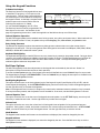
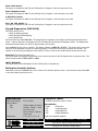
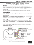
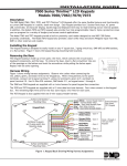
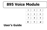
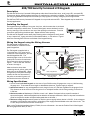
INSTALLATION
SHEET
690/790 Security Command LCD Keypads
Description
The 690 and 790 Security Command LCD Keypads provide three 2-button Panic keys, an AC power LED, an Armed LED,
32-character display, backlit keyboard with easy-to-read lettering, and a built-in speaker. The 790 additionally provides
four fully programmable Class B protection zones you can program for a variety of burglary and fire applications.
The 690F and 790F Security Command LCD keypads do not provide an Armed LED. These keypads may be installed in
fire only applications.
Installing the Keypad
The keypad housing is made up of two parts: the front, which contains the circuit board
and other components, and the base. To mount the keypad, remove the base from the
front by inserting a flat screwdriver into one of the openings on the bottom. Twist the
screwdriver while pulling the halves apart. Repeat with the other opening.
The 690 and 790 keypads use the same plastic housing and are designed to easily install
on any 4-square box, 3-gang switch box, 695 and 696 backbox, or flat surface. Figure 1
shows the mounting hole locations on the base of the keypad housing.
Wiring the Keypad using the Wiring Harness
The 690 keypad is supplied with a
4-wire harness for connection to the
panel's keypad bus.
The 790 keypad is supplied with a
12-wire harness. Four wires are for
connection to the keypad bus, just like
the 690 keypad harness. The
remaining eight wires are for the four
zone inputs: two wires for each zone.
The harness wire colors are shown in
Figure 1. Use 1k Ohm EOL resistors
on zones 1 through 4.
Observe the wire colors when
connecting the red, yellow, green, and
black wires to the keypad bus. When
wiring directly to the panel terminals,
connect the red wire the terminal 7,
the yellow to terminal 8, green to 9,
and the black wire the terminal 10.
Surface and Backbox
Mounting Holes
Surface and Backbox
Mounting Holes
1K EOL
1K EOL
1K EOL
Combined 4-Square and
3-Gang Switch Box
Mounting Holes
1K EOL
Yellow/White
- Zone 4
White/Yellow
Orange/White
- Zone 3
White/Orange
Red/White
- Zone 2
White/Red
Brown/White
- Zone 1
White/Brown
Black - Ground
Green - Receive Data
Yellow - Send Data
Red - Auxiliary Power
Back of Keypad Base
Surface and Backbox
Mounting Holes
Figure 1: 690/790 Keypad Base with 790 Harness
Wiring Specifications
1. You can install individual keypads on wire runs of up to 500 feet using 22-gauge wire or up to 1,000 feet using
18-gauge wire. To increase the wire length or add additional devices, a power supply is required.
2. Maximum distance for any one keypad bus circuit (length of wire) is 2,500 feet regardless of the gauge of wire.
This distance can be in the form of one long wire run or multiple branches with all wiring totaling no more than
2,500 feet.
3. Maximum number of devices per 2,500 feet circuit is 40. (Note: Each panel allows a specific number of
supervised keypads. Additional keypads can be added in the unsupervised mode. Refer to the panel’s installation
guide for the specific number of supervised keypads that are allowed.)
4. Maximum voltage drop between the panel (or auxiliary power supply) and any device is 2.0 VDC. If the voltage at
any device is less than the required level, an auxiliary power supply should be added at the end of the circuit. The
2.0 VDC drop minimum has not been verified by UL.
Refer to the 710 Module Installation Sheet (LT-0310) for more information. Also see the Trouble-Free LX-Bus/Keypad
Bus Wiring Application Note (LT-2031).
Using the Keypad Functions
2-Button Panic Keys
The Panic key function of the keypads allows users
to send Panic, Emergency, or Fire reports to the
central station. The user must press and hold the
two Select keys for two seconds until a beep from
the keypad is heard. At the beep, the panel sends
an alarm report to the central station with the
following zone numbers: 19 = Panic,
29 = non-medical Emergency, and 39 = Fire.
Top Row Select Keys
Police
Emergency
Label shows
icons only
Fire
Figure 2: Panic Key Label
The Panic key function must be programmed if the
Panic keys are to be used. See the back of this
page for programming instructions. Install the supplied icon label below the top row of Select keys.
Internal Speaker Operation
The 690/790 keypad speaker emits standard tones for key presses, entry delay, and system alerts. When used with the
XR200 Command Processor™ Panel, the speaker also provides burglary, fire, zone monitor, and prewarn tones.
Entry Delay Prewarns
The 690 and 790 keypads provide an alternative entry delay prewarn cadence that occurs when a zone alarm is
displayed in the status list. This function operates when the keypad is connected to an XRSuper6, XR20, XR40, XR200,
XR2400F, or XR200-485 Command Processor™ panel.
Keyboard Backlighting
The keyboard backlighting on the 690/790 turns on every time a key is pressed or the speaker sounds. During an alarm
condition, the keyboard illuminates in Red to visually alert people on the site. The Red backlighting turns off when all
areas in the system are disarmed or when the Sensor Reset function is used. The keyboard backlighting dims to
medium brightness whenever the speaker is on.
End-User Options
The 690/790 keypads provide three adjustments to the keypad that can be made by the end-user. Below is a
description of the options and instructions on their operation.
To access the User Options portion of the keypad, press and hold the Back Arrow and COMMAND keys for two seconds.
The keypad display changes to SET BRIGHTNESS. Press the COMMAND key to display the next option or the Back Arrow
key to exit the User Options function.
Backlighting Brightness
This option allows the user to set the brightness level of the keypad's Liquid Crystal Display (LCD), AC LED, and the
Green keyboard backlighting. At the SET BRIGHTNESS display, use the left Select key to lower the keypad brightness.
Use the right Select key to increase the brightness.
Note: If the brightness level is lowered, it temporarily reverts back to maximum intensity whenever a key is pressed.
If no keys have been pressed, and the speaker has not sounded for 30 seconds, the selected brightness is restored.
Internal Speaker Tone
This option allows the user to set the tone of the keypad's internal speaker. At the SET TONE display, use the top left
Select key to make the tone lower. Use the right Select key to make the tone higher.
Volume level
This option allows the user to set the volume level of the keypad's internal speaker for key presses and prewarn
conditions. During alarm, trouble, and prewarn conditions, the volume is always at maximum level. At SET VOLUME
LEVEL, use the left Select key to lower the keypad volume. Use the right Select key to raise the volume.
Model Number
The keypad's model number and firmware version and date are displayed, but cannot be changed by the user.
Keypad Address
The keypad's current address is displayed, but cannot be changed by the user. Press the Back Arrow key to exit the
User Options function.
690/790 Keypad Installation Sheet
2
Digital Monitoring Products
Installer Options: Keypad Options and Diagnostics
The 690 and 790 keypads also contain Keypad Options and Keypad Diagnostics programs that allows you to configure
and test the keypad operation.
You can only access the Installer Options function through the User Options function. After holding down the Back
Arrow and COMMAND keys for two seconds and getting the SET BRIGHTNESS display, enter the code 3577 (INST) and
press COMMAND. The display now changes to KPD OPT (keypad options) KPD DIAG (keypad diagnostics) and STOP.
Keypad Options (KPD OPT)
This option allows you to set the keypad address, select supervised or unsupervised mode, change the keypad display
message, and individually enable the 2-button Panic keys. To enter, press the left Select key under KPD OPT. The
display changes to CURRENT KEYPAD ADDRESS: # #.
Setting the Keypad Address
You can set the keypad address from 01 to 16. The factory default address is set at 01. To change the current
address, press any Select key to delete the old address and then press the appropriate number keys on the keyboard. It
is not necessary to enter a leading zero for addresses 01 to 09.
Selecting Supervised or Unsupervised Mode
You can configure the keypad for either supervised or unsupervised operation. Keypads that have zones connected to
them must be supervised. Supervised keypads cannot share addresses with other keypads.
To enhance the supervision feature, assign an output to the Device Fail Output in the panel’s programming and connect
a device to the corresponding output that will trip when the keypad fails. This provides notification at the central
station and the site. The other keypads will not display the device fail.
Note: The Device Fail Output cannot be used if there are any unsupervised devices on the system.
Unsupervised keypads can operate with other unsupervised keypads sharing the same address. Zones cannot be used
on unsupervised keypads. To change the current setting, press the Select key under SUP or UNSUP. An asterisk
appears next to the selected option.
Entering the Default Keypad Message
You can enter a custom message of up to 16 characters that appears on the top line of the keypad display whenever
that line is not being used for any other purpose. Press any Select key to clear the current display and use the data
entry keys to enter a new custom display.
Entering Alpha Characters
You can use the keypad to enter alpha characters. To
enter an alpha character, press the key that has the
desired letter written below it. The keypad display will
show the number on that key. To change the number to
a letter, press the top row Select key that corresponds to
the location of the letter under the key. For example, if
you press key number 1, the letters for that key are A, B,
and C. Press the first Select key for A, the second for B,
and the third for C. See Figure 3.
A
First Letter
Entering Non-Alphanumeric Characters
When in the Installer Options Menu, each key also has a
special, non-alpha character you may use. These characters are
not shown on the keypad, but they can be selected by following
the key map in Figure 4. Enter a space by pressing 9 then the
third Select key. The special characters available are as follows
starting with the 1 digit key to the 9 digit key: ( ) ! ? / & $ ‚ ’
and - . * # for the 0 key.
B
C
Second Letter
(
Third Letter Special Character
Figure 3: Entering Alpha Characters
1
2
3
4
ABC (
DEF )
GHI !
JKL ?
5
6
7
8
MNO /
PQR &
STU $
VWX ,
9
0
COMMAND
- . * #
YZ (space) '
Arming the 2-button Panic Keys
Figure 4: Letters and Characters Key Map
This option allows you to enable or disable the top row of Select keys
as 2-button Panic keys. To enable or disable a Panic, press the
Select key under the appropriate display: PN (Panic), EM (Emergency), and FI (Fire). Once the panic is enabled, an
asterisk appears next to the description. Refer to the 2-Button Panic Keys section in this document.
Digital Monitoring Products
690/790 Keypad Installation Sheet
3
Zone 2 Soft-Shunt™
This option is intended for DMP 791 and 793 Easy Entry™ Keypads. Leave the option set to NO.
Zone 3 Request to Exit
This option is intended for DMP 791 and 793 Easy Entry™ Keypads. Leave the option set to NO.
4-Digit Entry Cards
This option is intended for DMP 791 and 793 Easy Entry™ Keypads. Leave the option set to NO.
ALL? NO YES DELAY: 2
This option is intended for DMP 791 and 793 Easy Entry™ Keypads. Leave the option set to NO.
Keypad Diagnostics (KPD DIAG)
This option allows you to:
• check the display segments
• check the keyboard backlighting
• test individual keys
Press the Select key under KPD DIAG. The keypad lights all segments of the display and illuminates the keyboard in
Green. A few seconds later the keypad turns off the display and illuminates the keyboard in Red. The keypad then
alternates between these two states for approximately two minutes.
Press COMMAND at any time to continue. The display changes to PRESS KEY TO TEST. This option allows you to test
each key on the keyboard to ensure it's operating properly. Press and hold each key for about two seconds. The
number of the key being held appears in the display. Verify it is the correct number before testing the next key.
Zone test (790 Series keypads only)
This option allows the keypad to display the current electrical status of the 790 keypad's four protection zones. The
status is shown as either OPEN, SHRT, or OKAY.
INPUT WIEGAND
This option works on the DMP Model 791 and 793 Easy Entry™ Keypads only.
Exiting the Installer Options
Compatible Panels
Specifications
Operating Voltage:
Current Draw:
690
790
Dimensions:
8.0 to 16 VDC.
100mA standby and alarm
Standby: 100mA + 1.6mA
per active zone
Alarm: 100mA + 2mA per
active zone
6.75” W x 5” H x 1” D
800 - 641 - 4282
All DMP Command Processor® Panels
Accessories
Model
Description
695
Conduit Backbox
696
Keypad Backbox
699
Keypad Deskstand
DMP Zone Expander Modules
INTRUSION
•
FIRE •
ACCESS
•
NETWORKS
www.dmp.com
2500 North Partnership Boulevard
Made in the USA
Springfield, Missouri 65803-8877
LT-0263 (4/03) © 2003 Digital Monitoring Products, Inc.
When done, press the COMMAND key once to return to the Installer Options screen. Press the Select key under STOP
to exit the Installer Options function.