1
Optional Video Unit Function
Additional functions when the optional video unit is installed are as follows: ( 34 ∼ 45 )
INSTALLATION INSTRUCTIONS
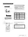
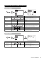
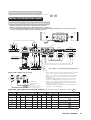
Connecting to a Video Imaging Device
(1) Make sure that the power switch of the monitor is turned off.
(2) Make sure that the power switch of the imaging device is turned off.
(3) Use a commercially available cable and connector to connect the signal input terminal on the rear panel of this
device and the signal output terminal of the imaging device.
Monitor rear panel
Speaker (R)
Speaker (L)
(exp.)
(exp.)
スピーカー端子
(6 12W)
スピーカー端子
(6 12W)
スピーカー端子
(6 12W)
スピーカー端子
(6 12W)
Power
cord
To composite
input terminal
To audio input
terminals
20
18
16
14
12
10
21 19
17
15
13
11
9
8
7
6
5
4
3
DVD player
2
Set-Top Box
1
VCR
VCR
To audio output
terminals
Use if the
video
equipment
has an
S video
input terminal
To component
output terminals
Video disc player
To component
input terminals
To composite
output terminal
To audio output
terminals
To S video output
terminal
Do not connect both
plugs at the same time.
Use either of them.
To audio output
terminals
S-video/Composite video
To component
output terminals
To component
input terminals
Adaptor
[An example of connecting video imaging devices]
• If video equipment with an S video output terminal is used, cabling
by the S video cable is recommended to provide finer video
quality. (If the S video input terminal and the video input terminal
of AV3 connect to the monitor at the same time, S video input
would govern.)
• If the OUTPUT (MONITOR) terminal is connected to an external
monitor with a 75 Ohm terminal, it is possible to view the same
image as on the main unit. But it is possible to monitor only the
composite video signal from AV1, AV2, AV3 or AV4 input that is
displayed on the screen at the time.
• If the adaptor is applied to AV4 input as shown in the drawing, it is
impossible to receive RGB signal.
With DVI-STB and RGB component setup
SUB WOOFER
To audio woofer
To component video
equipments.
Please use the connection
cable suitable for the terminal
form of video equipment.
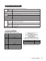
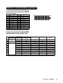
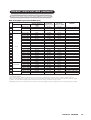
Applicable video signals for each input terminal (See PRODUCT SPECIFICATIONS for details.
Terminal
RCA/SCART
S-video
Signal
CVBS
AV1
○
○
AV2
○
○
AV3
○
○
AV4
○
○
RGB1
RGB2
Component
DVI
RGB
PC
RGB
Component
○
Refer to Setup Menu. 41
○
Refer to Setup Menu. 41
○
)
Remarks
D-sub
STB
43
Refer to Setup Menu. 42
○
○
○
Refer to Setup Menu. 42
(○ : Available)
ViewSonic VPW5500
34