1
QB-MINI2
R20UT0710EJ0200
Rev.2.00
Apr. 20, 2012
Release Note
Thank you for purchasing On-Chip Debugging Emulator with Programming Function QB-MINI2.
This document describes the items below.
See the user’s manual of the QB-MINI2 (hereafter referred to as
MINICUBE2) for cautions on using MINICUBE2.
• Restrictions not applicable to the target device but applicable to MINICUBE2
• Restrictions applicable to both the target device and MINICUBE2, but for which correction is planned only for
MINICUBE2
• Devices supported by MINICUBE2
See the following documents for the restrictions related to the target device.
• User’s manual of target device
• Restrictions notification document for target device
Chapter 1.
Product Version................................................................................................................... 2
Chapter 2.
Product History.................................................................................................................... 3
Chapter 3.
Details of Restrictions and Added Specifications................................................................ 5
Chapter 4.
Supported Devices ............................................................................................................ 13
Chapter 5.
Supplements ..................................................................................................................... 14
R20UT0710EJ0200 Rev.2.00
Apr. 20, 2012
Page 1 of 16
QB-MINI2
Release Note
Chapter 1.
Product Version
The product version is indicated by the following two items.
• Control code
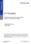
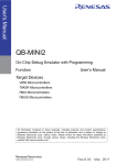
The control code is an alphabetic code used to identify the hardware of MINICUBE2. It is the second digit
from the left in the 10-digit serial number printed on the label on the bottom of MINICUBE2, if it has not been
upgraded. (See Figure 1-1 below.)
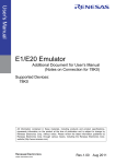
If the product has been upgraded, the control code can be checked by using the MINICUBE2 diagnostic tool
(see Figure 1-2 below).
Figure 1-1. Checking the Control Code
RENESAS
Produced xxxx
In this case, the control code is A.
QB-MINI2
SERIAL NO. SA ********
RENESAS Electronics Corporation
MADE IN JAPAN
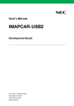
• Firmware version
Firmware (F/W) is a program embedded in MINICUBE2 to control its internal operations. The F/W version is
shown as Vx.xx. The version can be checked by using the MINICUBE2 diagnostic tool (see Figure 1-2
below).
Figure 1-2. Checking the Control Code and Firmware Version
Control code
R20UT0710EJ0200 Rev.2.00
Apr. 20, 2012
Firmware version
Page 2 of 16
QB-MINI2
Release Note
Chapter 2.
Product History
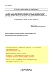
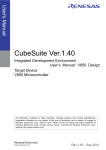
Table 2-1 lists the restrictions and the specifications that have been changed in or added to MINICUBE2.
Table 2-1.
No.
4.00
4.01
4.03
4.04
4.05
4.07
5.00
7.01
7.07
×
×
×
×
×
×
×
×
×
×
×
×
×
×
{
×
×
×
×
×
{
×
×
×
×
×
{
×
×
×
×
×
{
×
×
×
×
×
{
×
×
×
×
×
{
×
×
×
3.00
×
×
×
×
×
×
×
×
×
×
×
×
×
−
×
×
× × × × × × × × ×
{ { { { { { { { {
−
−
−
−
×
×
−
−
×
{
×
×
{
{
×
×
{
{
Δ
{
−
−
×
×
{ { { { { { {
−
×
−
−
−
×
−
−
×
×
×
×
×
×
×
×
{
{
×
{
−
−
−
−
×
−
×
−
×
−
{
{
×
{
{
× × ×
{ { {
Change of specification for reserved area when target is
connected via CSI
−
−
−
−
−
{ { { { { {
−
−
−
−
−
−
−
−
−
−
−
−
−
−
−
×
−
−
× × × × ×
{ { { { {
− { { { {
−
−
−
−
−
−
−
−
{ { {
P
Restriction on operation at low voltage
Addition of specifications on RRM and DMM
On-chip debugging and flash programming of devices that
have TOOLCx and TOOLDx pins
Addition of specification for supporting MINICUBE2 wireless
unit
Support of Renesas Flash Programmer
−
−
−
−
−
−
−
−
−
{ {
D
Addition of specification for supporting V850E2
−
−
−
−
−
−
−
−
−
−
78K0
V850
V850
V850
V850
V850
D
D
D
D
D
D
7
8
V850
78K0S
D
D
9
10
11
12
78K0S
78K0S
78K0R
78K0R
D
D
D
D
13
78K0R
D
14
15
16
17
78K0R
78K0
78K0R
78K0R
D
D
D
D
18
19
78K0R
V850
D
D
20
V850
D
21
22
23
V850
78K0R
78K0
D
D
D/P
24
All
D/P
78K0
78K0R
V850
26 V850
Changed or Added Specifications and Restrictions
×
×
×
×
×
×
1
2
3
4
5
6
25
Control Code
A
F/W Version
2.00
Target
D/PNote
Device
Restrictions and Changed or Added Specifications
Internal high-speed RAM values become invalid after reset
Restriction regarding watchdog timer
Restriction on break during subclock operation
Restriction regarding break during flash macro servicing
Restriction regarding reset vector handling
Restriction on rewriting registers that require a specific
sequence
Restriction when a reset occurs
Restriction on debugging with operating clock of 6 MHz or
lower
Restriction on downloading when operating clock is 10 MHz
Restriction on display of register values
Restriction on breakpoint for a CPU clock lower than 2 MHz
Restriction on debugging of time measurement in 1-wire
mode
Restriction regarding invalid operation after program
download
Restriction on using MINICUBE2 with USB 1.1
Restriction on operation at 20 MHz or higher
Restriction on general-purpose registers after reset
Specifications changed/added in conjunction with firmware
optimization
Restriction on hardware breaks
Improvement of downloading speed when target is connected
via CSI
R20UT0710EJ0200 Rev.2.00
Apr. 20, 2012
{
{
Δ
{
{
{
×
{
{
{
Δ
{
{
{
Δ
{
{
{
×
{
{
{
Δ
{
{
{
Δ
{
{
{
Δ
{
{ { {
{ { {
× × ×
× × ×
{ { {
Page 3 of 16
{
QB-MINI2
Release Note
{: Restriction is not applicable or has already been corrected. Changed or added specifications apply.
Δ: Restriction has been partially corrected.
×: Restriction is applicable.
Changed or added specifications do not apply.
−: Not relevant or the target device is not supported
Note
D: Applicable during debugging, P: Applicable during programming.
Remark A permanent restriction means a restriction that will not be corrected.
R20UT0710EJ0200 Rev.2.00
Apr. 20, 2012
Page 4 of 16
QB-MINI2
Chapter 3.
Release Note
Details of Restrictions and Added Specifications
No. 1 Internal high-speed RAM values become invalid after reset
[Target device] 78K0
[Description]
If a reset signal is input via the RESET pin during program execution, the internal high-speed RAM areas shown
below become invalid. This does not occur when a reset is triggered by a source such as the watchdog timer or LVI.
- 5 bytes from FECBh to FECFh
(When Permit is selected for Target Power OFF in the Configuration dialog box)
- 10 bytes from FEC9h to FECFh and FEDDh to FEDFh
(When Not Permit is selected for Target Power OFF in the Configuration dialog box)
[Workaround]
There is no workaround.
No. 2 Restriction regarding watchdog timer
[Target device] V850
[Description]
The watchdog timer is forcibly stopped by the debug monitor program. Therefore, do not use the option byte to
specify that the watchdog timer cannot be stopped. For details about the option byte settings, see the user’s manual
of the target device.
[Workaround]
There is no workaround.
No. 3 Restriction on break during subclock operation
[Target device] V850
[Description]
When the mode for communication between MINICUBE2 and the target device is UART, and if a break occurs during
subclock operation while the main clock is stopped, the debug monitor program forcibly switches the operating clock
to the main clock. The device continues operating on the main clock, even after execution resumes.
Whether the
operating clock during a break is switched from the subclock to the main clock depends on the Monitor Clock setting
in the Configuration dialog box of the debugger.
[Workaround]
There is no workaround.
This issue has been corrected in firmware V4.04. If you are using the Renesas Electronics debugger ID850QB,
please switch to ID850QB V3.40 or later.
R20UT0710EJ0200 Rev.2.00
Apr. 20, 2012
Page 5 of 16
QB-MINI2
Release Note
No. 4 Restriction regarding break during flash macro servicing
[Target device] V850
[Description]
If a break occurs during flash macro servicing, it occurs at an unexpected address. This also applies if a break
occurs in the debugger, such as when using pseudo RRM.
[Workaround]
There is no workaround. Reset the device and re-execute the program.
No. 5 Restriction regarding reset vector handling
[Target device] V850
[Description]
Reset vector handling is not supported.
[Workaround]
There is no workaround.
No. 6 Restriction on rewriting registers that require a specific sequence
[Target device] V850
[Description]
Peripheral I/O registers (other than PCC and CKC) that require a specific sequence cannot be rewritten in debugger
windows such as the I/O register window.
[Workaround]
There is no workaround.
No. 7 Restriction when a reset occurs
[Target device] V850
[Description]
A break occurs when an external reset occurs (except when resets are masked) or an internal reset occurs.
[Workaround]
There is no workaround.
No. 8 Restriction on debugging with operating clock of 6 MHz or lower
[Target device] 78K0S
[Description]
The debugger does not start when the target device operating frequency is 6 MHz or lower.
[Workaround]
There is no workaround. This issue has been corrected in firmware V4.00.
R20UT0710EJ0200 Rev.2.00
Apr. 20, 2012
Page 6 of 16
QB-MINI2
Release Note
No. 9 Restriction on downloading when operating clock is 10 MHz
[Target device] 78K0S
[Description]
When the target device operating frequency is 10 MHz, an error will occur when a program is being downloaded and
downloading cannot be completed.
[Workaround]
There is no workaround. This issue has been corrected in firmware V4.01. If you are using the Renesas
Electronics debugger ID78K0S-QB, please switch to ID78K0S-QB V2.90 or later.
No. 10 Restriction on display of register values
[Target device] 78K0S
[Description]
The register values might be displayed incorrectly in the debugger when a break occurs.
[Workaround]
There is no workaround. This issue has been corrected in firmware V4.00.
No. 11 Restriction on breakpoint for a CPU clock lower than 2 MHz
[Target device] 78K0R
[Description]
If a break occurs when the CPU is operating on a clock (fCLK) with a frequency lower than 2 MHz while the PER0 and
PER1 registers are set to 0, the internal flash memory cannot be rewritten.
Consequently, the following operations
cannot be performed:
<1> Writing to internal flash memory
<2> Setting or canceling software breakpoints
<3> Starting execution at the specified software breakpoint
<4> Stepping through code at the specified software breakpoint
<5> Stepping through code, executing Return Out
<6> Executing Come Here
<7> If Permit is selected in the Flash Programming area in the Configuration dialog box, the following
operations cannot be performed:
(a) Setting, changing, or canceling hardware breakpoints
(b) Masking and unmasking internal resets
(c) Switching peripheral breakpoints
[Workaround]
There is no workaround. To specify a breakpoint for an operation performed on a CPU clock lower than 2 MHz, use
a hardware breakpoint, not a software breakpoint.
This restriction is partially corrected in firmware V4.03, as shown below.
To apply this correction, please use the
Renesas Electronics debugger ID78K0R-QB V3.30 or later.
R20UT0710EJ0200 Rev.2.00
Apr. 20, 2012
Page 7 of 16
QB-MINI2
Release Note
[Correction]
To avoid the CPU operating on a clock with a frequency at which the flash memory cannot be written, the
specifications will be changed so that a frequency that enables flash memory rewriting is selected automatically, and
the register settings are restored after flash memory rewriting is completed. To prevent the frequency from being
switched automatically, select User in the Monitor Clock area and Not Permit in the Flash Programming area in
the ID78K0R-QB Configuration dialog box.
Note, however, that specifying this setting means that the operations
<1> to <7> above can no longer be performed.
No. 12 Restriction on debugging of time measurement in 1-wire mode
[Target device] 78K0R
[Description]
When debugging is performed in 1-wire mode (selected by choosing TOOL0 in the Target Device Connection area
in the Configuration dialog box of the debugger), the Run-Break execution time is measured with an accuracy of
roughly 10 ms order. The prescribed accuracy is 100 μs.
[Workaround]
Perform debugging in 2-wire mode (TOOL0 + TOOL1).
This issue has been corrected in firmware V4.03. If you are using the Renesas Electronics debugger ID78K0R-QB,
please switch to ID78K0R-QB V3.30 or later.
No. 13 Restriction regarding invalid operation after program download
[Target device] 78K0R
[Description]
When the reset vector (addresses 0 and 1) is assigned to an address lower than 0x0100, the debugger malfunctions
after a program is downloaded. Specifically, illegal breaks occur immediately after execution, the Source window
cannot be opened.
[Workaround]
Assign the reset vector for the user program to an address of 0x0100 or higher.
This issue has been corrected in firmware V4.03. If you are using the Renesas Electronics debugger ID78K0R-QB,
please switch to ID78K0R-QB V3.30 or later.
No. 14 Restriction on using MINICUBE2 with USB 1.1
[Target device] 78K0R
[Description]
The debugger might malfunction if MINICUBE2 is connected via a USB 1.1 interface.
[Workaround]
There is no workaround. This issue has been corrected in firmware V4.03.
R20UT0710EJ0200 Rev.2.00
Apr. 20, 2012
Page 8 of 16
QB-MINI2
Release Note
No. 15 Restriction on operation at 20 MHz or higher
[Target device] 78K0R
[Description]
When MINICUBE2 operates on a frequency of 20 MHz or higher, downloading or changing the memory contents
might fail.
[Workaround]
Download or change the memory contents at a frequency lower than 20 MHz.
This issue has been corrected in firmware V4.03.
No. 16 Restriction on general-purpose registers after reset
[Target device] 78K0R
[Description]
The general-purpose register contents are not retained after a reset in standby mode.
[Workaround]
There is no workaround.
No. 17 Specifications changed/added in conjunction with firmware optimization
[Target device] 78K0R
[Description]
The specifications below have been changed or added in conjunction with firmware optimization. These changes
apply from the 2nd edition of the MINICUBE2 user’s manual.
The optimized firmware is V4.03. If you are using the Renesas Electronics debugger ID78K0R-QB, please switch to
V3.30 or later.
<1> The debugger operating speed has been raised by improving the MINICUBE2 firmware processing.
<2> The operating speed in 1-wire mode has been raised to the level of 2-wire mode.
<3> When pseudo real-time monitoring (RRM) is not used during debugging in 2-wire mode, the size of the debug
monitor program allocated to the last block in the internal ROM is reduced from 1 KB to 88 bytes.
<4> Instructions that execute two instructions while stepping through code have been modified so as to execute only
one instruction.
<5> The option byte setting (C1H) for the LVI default start function is now the same regardless of whether
MINICUBE2 is connected.
R20UT0710EJ0200 Rev.2.00
Apr. 20, 2012
Page 9 of 16
QB-MINI2
Release Note
<6> Debugger operations for rewriting the flash memory (such as downloading memory data and setting software
breaks), which were not possible when the target microcontroller could not rewrite the flash memory due to the
CPU clock or the regulator mode can now be executed because the specification has been changed so that the
debugger automatically changes the SFR contents so as to enable rewriting of the flash memory. (Correction of
restriction No. 11 is also included in this change.) After the flash memory is rewritten, the SFR contents will be
restored. The debugger will output the errors below if the operation voltage is lower than the voltage at which
flash memory rewriting is disabled (1), or if flash memory rewriting is prohibited by the debugger configuration
(2). (This applies when using the ID78K0R-QB.)
• For (1):
F0C37: The voltage is too low to operate flash programming.
• For (2):
F0C48: Flash programming is disabled in the debugger.
• For (1) or (2) and when setting or cancelling software breakpoints:
W401C: Software break can not be set on this area.
<7> The break that was generated if STOP mode was entered when pseudo RRM was used is now prevented by
cancelling the STOP mode.
No. 18 Restriction on hardware breaks
[Target device] 78K0R
[Description]
A hardware break occurs at an address several instructions after the specified point. This applies to both instruction
fetch and data access. If any of the debugger operations <1> to <3> below is executed while rewriting the flash
memory is disabled, a hardware break occurs at an address several instructions after the specified point.
<1> Stepping through code
<2> Return Out
<3> Come Here
[Workaround]
There is no workaround.
No. 19 Improvement of downloading speed when target is connected via CSI interface
[Target device] V850
[Description]
The downloading speed when connecting MINICUBE2 to the target system via the CSI interface has been
approximately doubled.
This specification change applies from firmware V4.04. If you are using the Renesas Electronics debugger ID850QB,
please switch to ID850QB V3.40 or later.
[Caution]
When the ID850QB is upgraded to V3.40, it does not start if firmware is V4.03 or earlier.
Be sure to upgrade the
firmware to V4.04 or later when upgrading the ID850QB to V3.40 and when connecting MINICUBE2 to the target
system via UART, even though the new specification does not apply to this case.
R20UT0710EJ0200 Rev.2.00
Apr. 20, 2012
Page 10 of 16
QB-MINI2
Release Note
No. 20 Change of specification for reserved area when target is connected via CSI
[Target device] V850ES/IE2
[Description]
The reception error interrupt can now be used when MINICUBE2 is connected to the target system via the CSI
interface. This is implemented to prevent the debugger hanging up when a reception error occurs.
This specification change applies from firmware V4.04. If you are using the Renesas Electronics debugger ID850QB,
please switch to ID850QB V3.40 or later.
[Caution]
When the ID850QB is upgraded to V3.40, it does not start if firmware is V4.03 or earlier.
Be sure to upgrade the
firmware to V4.04 or later when upgrading the ID850QB to V3.40 and connecting MINICUBE2 to the target system via
UART, even though the new specification does not apply to this case.
No. 21 Restriction on operation at low voltage
[Target device] V850ES/JF3-L, V850ES/JG3-L
[Description]
When debugging on a voltage of less than 2.7 V, MINICUBE2 and the target device cannot communicate correctly,
causing a malfunction. Be sure to debug on a voltage of at least 2.7 V.
[Workaround]
There is no workaround.
No. 22 Addition of specifications on RRM and DMM
[Target device] 78K0R
[Description]
The specifications <1> to <3> below have been added. These specifications are added in firmware V4.05 and later.
If you are using the Renesas Electronics debugger ID78K0R-QB, please switch to ID78K0R-QB V3.50 or later.
<1>
Pseudo RRM is now supported in 1-wire mode. (This was supported only in 2-wire mode in older versions.)
<2>
The entire memory space can now be monitored when using pseudo RRM. (This was available only for a
16-byte space in older versions.) Note that if the targets to be monitored are too numerous, the operability of
the debugger might be affected because the monitoring speed is slow when using pseudo RRM in 1-wire
mode. When using the ID78K0R-QB, therefore, monitoring by using the Watch window, rather than the
Memory window, is recommended.
<3>
Direct memory modification (DMM) can now be used and the contents in the RAM can now be changed during
program execution. When using DMM, program execution stops. Consequently, the memory contents are
not changed in real time.
R20UT0710EJ0200 Rev.2.00
Apr. 20, 2012
Page 11 of 16
QB-MINI2
Release Note
No. 23 On-chip debugging and flash programming of devices that have TOOLCx and TOOLDx pins
[Target device] 78K0
[Description]
On-chip debugging and flash programming of devices that have the TOOLCx and TOOLDx pins can now be executed.
This specification is added in firmware V4.07 and later. If you are using the Renesas Electronics debugger
ID78K0-QB, please switch to ID78K0-QB V3.10 or later.
[Caution]
When the ID78K0-QB is upgraded to V3.10, be sure to upgrade the firmware to V4.07 or later.
No. 24 Addition of specification for supporting MINICUBE2 wireless unit
[Target device] 78K0S, 78K0, 78K0R, V850
[Description]
A wireless unit for MINICUBE2 (sold separately) is now available. This specification is added to firmware V5.00 or
later.
[Caution]
This unit can be used for all 78K0S, 78K0, 78K0R, and V850 microcontrollers, but whether a microcontroller is
supported varies depending on the version of the debugger used. For details about the supported devices, see the
Web page for the wireless unit, which is linked to the MINICUBE2 information site.
No. 25 Support of Renesas Flash Programmer
[Target device] 78K0, 78K0R, V850
[Description]
Flash programming software Renesas Flash Programmer was supported. This specification is added to firmware
V7.01 or later.
No. 26 Addition of specification for supporting V850E2
[Target device] V850
[Description]
V850E2 was supported. This specification is added to firmware V7.07 or later.
R20UT0710EJ0200 Rev.2.00
Apr. 20, 2012
Page 12 of 16
QB-MINI2
Release Note
Chapter 4.
Supported Devices
Information on the supported devices is also available on the following CubeSuite+ website and Renesas Flash
Programmer website.
CubeSuite+ website: http://www.renesas.com/cubesuite+
Renesas Flash Programmer website: http://www.renesas.com/rfp
R20UT0710EJ0200 Rev.2.00
Apr. 20, 2012
Page 13 of 16
QB-MINI2
Release Note
Chapter 5.
5.1
Supplements
Supplement for RRM Executed for 78K0 Microcontrollers
This section provides supplementary information on specifying the ROM area (debug monitoring area +
pseudo RRM area) used for CubeSuite+ when executing pseudo real-time RAM monitoring (RRM) for 78K0
microcontrollers.
Microcontrollers
Debug monitoring area (include RRM area) size that must be allocated
In case of not using RRM function (Byte)
In case of using RRM function (Byte)
78K0/Kx2-L
78K0/Fx2-L
78K0/Ix2
78K0/Kx2
78K0/Kx2-A
78K0/Kx2-C
78K0/Lx3
78K0/Lx3-M
78K0/Fx2
78K0/Dx2
μPD78F0730
μPD78F8039
R20UT0710EJ0200 Rev.2.00
Apr. 20, 2012
256
384
256
Page 14 of 16
QB-MINI2
5.2
Release Note
Supplement for debugging interface for V850 Microcontrollers
The serial interface that can be used for the debugging interface of MINICUBE2 and the V850
Microcontrollers is supplemented.
Microcontrollers
V850ES/HE2
V850ES/HF2
V850ES/HG2
V850ES/HJ2
V850ES/HE3
V850ES/HF3
V850ES/HG3
V850ES/HJ3
V850ES/IE2
V850ES/JG2
V850ES/JJ2
V850ES/JG3
V850ES/JJ3
V850ES/JC3-L
V850ES/JE3-L
V850ES/JF3-L
V850ES/JG3-L
V850ES/JC3-H
V850ES/JE3-H
V850ES/JG3-H
V850ES/JH3-H
V850ES/JG3-U
V850ES/JH3-U
V850ES/JJ3-E
V850ES/JH3-E
V850ES/KE2
V850ES/KF2
V850ES/KG2
V850ES/KJ2
注1
V850ES/KE1
注1
V850ES/KF1
注1
V850ES/KG1
注1
V850ES/KJ1
V850ES/KE1+
V850ES/KF1+
V850ES/KG1+
V850ES/KJ1+
Debugging interface
UARTA0/CSIB0
UARTA0/CSIB0
UARTA0/CSIB0
UARTA0/CSIB0/CSIB3
UARTA0/CSIB0/CSIB3
UARTA0/CSIB0
UARTA0/CSIB0/CSIB3
UARTC0/CSIF0/CSIF3
UARTC0/CSIF0/CSIF3
UART0/CSI0
UART0/CSI0
UART0/CSI0
Microcontrollers
V850ES/FE2
V850ES/FF2
V850ES/FG2
V850ES/FJ2
V850ES/FE3
V850ES/FF3
V850ES/FG3
V850ES/FJ3
V850ES/FK3
V850ES/FE3-L
V850ES/FF3-L
V850ES/FG3-L
V850E/IA3
V850E/IA4
V850ES/IK1
V850ES/SG2
V850ES/SJ2
V850ES/SG3
V850ES/SJ3
V850ES/SJ3-H
V850ES/SK3-H
V850E/DG3
V850E/DJ3
V850ES/MA3
V850E/IF3
V850E/IG3
V850E/IG4
V850E/IH4
V850E/IG4-H
V850E/IH4-H
V850E2/FF4-M
V850E2/FG4
V850E2/FG4-L
V850E2/FJ4
V850E2/FK4
V850E2/FK4-H
V850E2/FL4
V850E2/FL4-H
V850E2/SK4-H
Debugging interface
UARTA0/CSIB0
注2
UARTD0/CSIB0
注2
UARTD0/CSIB0
UARTA0/CSIB0
UARTA0/CSIB0
UARTA0/CSIB0/CSIB3
UARTA0/CSIB0/CSIB3
UARTA0/CSIB0/CSIB3
UARTA0/CSIB0
UARTA0/CSIB0
UARTA0/CSIB0
UARTA0/CSIF0
UART
Note1:Supported only in single-power-supply products (product name suffixed by H)
Note2:When using UARTD0, fRH cannot be used as the CPU clock.
All trademarks and registered trademarks are the property of their respective owners.
R20UT0710EJ0200 Rev.2.00
Apr. 20, 2012
Page 15 of 16
Notice
1.
All information included in this document is current as of the date this document is issued. Such information, however, is subject to change without any prior notice. Before purchasing or using any Renesas
Electronics products listed herein, please confirm the latest product information with a Renesas Electronics sales office. Also, please pay regular and careful attention to additional and different information to
be disclosed by Renesas Electronics such as that disclosed through our website.
2.
Renesas Electronics does not assume any liability for infringement of patents, copyrights, or other intellectual property rights of third parties by or arising from the use of Renesas Electronics products or
technical information described in this document. No license, express, implied or otherwise, is granted hereby under any patents, copyrights or other intellectual property rights of Renesas Electronics or
others.
3.
You should not alter, modify, copy, or otherwise misappropriate any Renesas Electronics product, whether in whole or in part.
4.
Descriptions of circuits, software and other related information in this document are provided only to illustrate the operation of semiconductor products and application examples. You are fully responsible for
the incorporation of these circuits, software, and information in the design of your equipment. Renesas Electronics assumes no responsibility for any losses incurred by you or third parties arising from the
use of these circuits, software, or information.
5.
When exporting the products or technology described in this document, you should comply with the applicable export control laws and regulations and follow the procedures required by such laws and
regulations. You should not use Renesas Electronics products or the technology described in this document for any purpose relating to military applications or use by the military, including but not limited to
the development of weapons of mass destruction. Renesas Electronics products and technology may not be used for or incorporated into any products or systems whose manufacture, use, or sale is
prohibited under any applicable domestic or foreign laws or regulations.
6.
Renesas Electronics has used reasonable care in preparing the information included in this document, but Renesas Electronics does not warrant that such information is error free. Renesas Electronics
7.
Renesas Electronics products are classified according to the following three quality grades: "Standard", "High Quality", and "Specific". The recommended applications for each Renesas Electronics product
assumes no liability whatsoever for any damages incurred by you resulting from errors in or omissions from the information included herein.
depends on the product's quality grade, as indicated below. You must check the quality grade of each Renesas Electronics product before using it in a particular application. You may not use any Renesas
Electronics product for any application categorized as "Specific" without the prior written consent of Renesas Electronics. Further, you may not use any Renesas Electronics product for any application for
which it is not intended without the prior written consent of Renesas Electronics. Renesas Electronics shall not be in any way liable for any damages or losses incurred by you or third parties arising from the
use of any Renesas Electronics product for an application categorized as "Specific" or for which the product is not intended where you have failed to obtain the prior written consent of Renesas Electronics.
The quality grade of each Renesas Electronics product is "Standard" unless otherwise expressly specified in a Renesas Electronics data sheets or data books, etc.
"Standard":
Computers; office equipment; communications equipment; test and measurement equipment; audio and visual equipment; home electronic appliances; machine tools;
personal electronic equipment; and industrial robots.
"High Quality": Transportation equipment (automobiles, trains, ships, etc.); traffic control systems; anti-disaster systems; anti-crime systems; safety equipment; and medical equipment not specifically
designed for life support.
"Specific":
Aircraft; aerospace equipment; submersible repeaters; nuclear reactor control systems; medical equipment or systems for life support (e.g. artificial life support devices or systems), surgical
implantations, or healthcare intervention (e.g. excision, etc.), and any other applications or purposes that pose a direct threat to human life.
8.
You should use the Renesas Electronics products described in this document within the range specified by Renesas Electronics, especially with respect to the maximum rating, operating supply voltage
range, movement power voltage range, heat radiation characteristics, installation and other product characteristics. Renesas Electronics shall have no liability for malfunctions or damages arising out of the
use of Renesas Electronics products beyond such specified ranges.
9.
Although Renesas Electronics endeavors to improve the quality and reliability of its products, semiconductor products have specific characteristics such as the occurrence of failure at a certain rate and
malfunctions under certain use conditions. Further, Renesas Electronics products are not subject to radiation resistance design. Please be sure to implement safety measures to guard them against the
possibility of physical injury, and injury or damage caused by fire in the event of the failure of a Renesas Electronics product, such as safety design for hardware and software including but not limited to
redundancy, fire control and malfunction prevention, appropriate treatment for aging degradation or any other appropriate measures. Because the evaluation of microcomputer software alone is very difficult,
please evaluate the safety of the final products or system manufactured by you.
10. Please contact a Renesas Electronics sales office for details as to environmental matters such as the environmental compatibility of each Renesas Electronics product. Please use Renesas Electronics
products in compliance with all applicable laws and regulations that regulate the inclusion or use of controlled substances, including without limitation, the EU RoHS Directive. Renesas Electronics assumes
no liability for damages or losses occurring as a result of your noncompliance with applicable laws and regulations.
11. This document may not be reproduced or duplicated, in any form, in whole or in part, without prior written consent of Renesas Electronics.
12. Please contact a Renesas Electronics sales office if you have any questions regarding the information contained in this document or Renesas Electronics products, or if you have any other inquiries.
(Note 1)
"Renesas Electronics" as used in this document means Renesas Electronics Corporation and also includes its majority-owned subsidiaries.
(Note 2)
"Renesas Electronics product(s)" means any product developed or manufactured by or for Renesas Electronics.
http://www.renesas.com
SALES OFFICES
Refer to "http://www.renesas.com/" for the latest and detailed information.
Renesas Electronics America Inc.
2880 Scott Boulevard Santa Clara, CA 95050-2554, U.S.A.
Tel: +1-408-588-6000, Fax: +1-408-588-6130
Renesas Electronics Canada Limited
1101 Nicholson Road, Newmarket, Ontario L3Y 9C3, Canada
Tel: +1-905-898-5441, Fax: +1-905-898-3220
Renesas Electronics Europe Limited
Dukes Meadow, Millboard Road, Bourne End, Buckinghamshire, SL8 5FH, U.K
Tel: +44-1628-585-100, Fax: +44-1628-585-900
Renesas Electronics Europe GmbH
Arcadiastrasse 10, 40472 Düsseldorf, Germany
Tel: +49-211-65030, Fax: +49-211-6503-1327
Renesas Electronics (China) Co., Ltd.
7th Floor, Quantum Plaza, No.27 ZhiChunLu Haidian District, Beijing 100083, P.R.China
Tel: +86-10-8235-1155, Fax: +86-10-8235-7679
Renesas Electronics (Shanghai) Co., Ltd.
Unit 204, 205, AZIA Center, No.1233 Lujiazui Ring Rd., Pudong District, Shanghai 200120, China
Tel: +86-21-5877-1818, Fax: +86-21-6887-7858 / -7898
Renesas Electronics Hong Kong Limited
Unit 1601-1613, 16/F., Tower 2, Grand Century Place, 193 Prince Edward Road West, Mongkok, Kowloon, Hong Kong
Tel: +852-2886-9318, Fax: +852 2886-9022/9044
Renesas Electronics Taiwan Co., Ltd.
13F, No. 363, Fu Shing North Road, Taipei, Taiwan
Tel: +886-2-8175-9600, Fax: +886 2-8175-9670
Renesas Electronics Singapore Pte. Ltd.
1 harbourFront Avenue, #06-10, keppel Bay Tower, Singapore 098632
Tel: +65-6213-0200, Fax: +65-6278-8001
Renesas Electronics Malaysia Sdn.Bhd.
Unit 906, Block B, Menara Amcorp, Amcorp Trade Centre, No. 18, Jln Persiaran Barat, 46050 Petaling Jaya, Selangor Darul Ehsan, Malaysia
Tel: +60-3-7955-9390, Fax: +60-3-7955-9510
Renesas Electronics Korea Co., Ltd.
11F., Samik Lavied' or Bldg., 720-2 Yeoksam-Dong, Kangnam-Ku, Seoul 135-080, Korea
Tel: +82-2-558-3737, Fax: +82-2-558-5141
© 2012 Renesas Electronics Corporation. All rights reserved.
Colophon 1.1