1
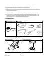
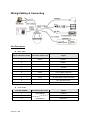
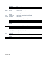
HARDWARE INSTALLATION GUIDE VPD200SM2i FULL HD NETWORK PTZ Camera Version 1. 0. 0 Released on 1 of June., 2012 st Vision Hitech Co., Ltd. Page 1 / 15 PRECAUTIONS By selecting this product, you have decided to use a professional device that guarantees highest quality and reliability. We would like to thank you very much for your confidence and kindly ask you to read the following instructions carefully before installation and operation in order to take full advantage of all quality features regarding this product. The lighting flash with an arrowhead symbol, within an equilateral triangle is intended to alert the user to the presence of non-insulated dangerous voltage within the product’s enclosure that may be of sufficient magnitude to constitute a risk of electric shock to persons. The exclamation point within an equilateral triangle is intended to alert the user to the presence of important operating and maintenance (servicing) instructions in the literature accompanying the appliance. INFORMATION This equipment has been tested and found to comply with limits for a Class A digital device, pursuant to part 15 of the FCC Rules. These limits are designed to provide reasonable protection against harmful interference when the equipment is operated in a commercial environment. This equipment generates, uses, and can radiate radio frequency energy and, if not installed and used in accordance with the instruction manual, may cause harmful interference to radio communications. Operation of this equipment in a residential area is likely to cause harmful interference in which case the user will be required to correct the interference at its own expense. WARNING Changes or modifications not expressly approved by the manufacturer could void the user’s authority to operate the equipment. CAUTION – To prevent electric shock and risk of the fire hazards -Do NOT use power source other than that specified. -Do NOT expose this appliance to rain or moisture. Trademarks All names used in this manual for hardware and software are probably registered trademarks of respective companies. This installation should be made by a qualified service person and should conform to all local codes. Page 2 / 15 Table of content Hardware Installation Guide 1. Precautions ---------------------------------------------------------------------------------------------------- 4 2. Limitation of liability ---------------------------------------------------------------------------------------- 4 3. Disclaimer of warranty ------------------------------------------------------------------------------------- 4 4. Package Contents --------------------------------------------------------------------------------------------- 5 5. Cable Connection --------------------------------------------------------------------------------------------- 6 6. Installation ----------------------------------------------------------------------------------------------7~13 7. Dimension (mm) ----------------------------------------------------------------------------------------------- 14 8. Specification ----------------------------------------------------------------------------------------------------- 14 VPD200SM2i Page 3 / 15 ------------------------------------------------------------------------------------------- 15 1. Precautions Please read the manual carefully before the installation in order to set up the camera correctly and to obtain the best picture quality. Please keep the manual in good condition for your future reference and service application. Installation and services should be only carried out by an authorized personnel according to local safety regulations. If any liquid or solid matter gets into the housing, immediately disconnect the camera from power supply and have it checked by your authorized dealer before reusing. Avoid installing the camera at extremely hot or cold places. If you are not a certified person, never try to dismantle the camera. To avoid electric shock, never remove the screws or covers. There are no parts inside that need maintenance by the user. All maintenance should be carried out by qualified personnel. Avoid installing the camera at a place of high humidity. Avoid installing the camera at the place exposed to gas or oil. Keep the top glass of the lens always clean in order to obtain the best picture quality all the time. Be careful not to be stained by fingerprint. Don't face the camera directly toward sunlight or sunlight reflecting area. CCD may go defective at this condition. Please give a special attention to keep the unit from dangerous drop or external shock during the process of transportation or handling. Never try to touch the camera in wet hand. It may cause an electric shock. Do not expose the camera to radioactivity. It causes a serious damage on the CCD. 2. Limitation of liability This publication is provided “AS IS” without warranty of any kind, either express or implied, including but not limited to, the implied warranties of merchantability, fitness for any particular purpose, or non-infringement of the third party's right. This publication could include technical inaccuracies or typographical errors. Changes are added to the information herein, at any time, for the improvements of this publication and/or the corresponding product(s). 3. Disclaimer of warranty In no event shall seller be liable to any party or any person, except for replacement or reasonable maintenance of the product, for the cases, including but not limited to below: (1) Any damage and loss, including without limitation, direct or indirect, special, consequential or exemplary, arising out of or relating to the product; Page 4 / 15 (2) Personal injury or any damage caused by inappropriate use or negligent operation of the user; (3) Unauthorized disassemble, repair or modification of the product by the user; (4) Inconvenience or any loss arising when images are not displayed, due to any reason or cause including any failure or problem of the product; (5) Any problem, consequential inconvenience, or loss or damage, arising out of the system combined by the devices of third party. (6) Any claim or action for damages, brought by any person or organization being photogenic subject, due to violation of privacy with the result of that surveillance-camera's picture, including saved data, for some reason, becomes public or is used for the purpose other than surveillance. 4. Package Contents Main body & Dome Cover Accessories Main Cable Wrench Driver Cross LAN Cable Audio Cable 2EA of BNC CD Note: Mount Brackets are optional. Wall Mount Bracket [Screws : Torx Secrew M418, Hex Lag #1450] Page 5 / 15 Ceiling Mount Bracket [Screws : Torx Screw M418, Anchor Bolt 3/8"70] 5. Cable Connection • Dome Cover Do not detach protection vinyl from dome cover before finishing all installation process to protect dome cover from scratches or dust. • DIP Switch Sets up camera ID and protocol. • Drop Prevention Spring This part keeps the camera from dropping during installation and maintenance. After install the Bracket, please, hang the spring to the drop prevention hook of main body as shown in picture for further tasks. • Mounting Screw Hole This hole is for screws that assembles the main body with a bracket. • IP Reset Switch Reset its network configuration to the factory defaults. You will lose all data that had been entered previously. To initialize the system to the factory default, press the reset button for more than 5 seconds. • LAN Port Used for the Ethernet connection • Audio Port Used for the audio in/out connection. • Video (BNC) Used for the composite video out or HD-SDI video out connection according to models • Main Connector Used for the power wire, the RS-485 communication cable, alarm in/out connection cable. Page 6 / 15 6. Installation DIP Switch Setup When you control the camera through RS-485, before installation, you should set the DIP switches to configure the camera ID, communication protocol. Camera ID setup ON ON ID numbers of camera are set up with binary numbers.. See the examples shown below 1 2 Page 7 / 15 3 4 5 6 7 8 Pin 1 2 3 4 5 6 7 8 ID Value 1 2 4 8 16 32 64 128 ex) ID=5 on off On off off off off off ex) ID=10 off on Off on off off off off The camera ID range is 1~255. Camera ID must not be 0. Factory default of Camera ID is 1. Match the camera ID with Cam ID setting of your DVR or Controller to control the camera. Communication Protocol Setup ON ON 1 2 3 4 Select the appropriate Protocol with DIP switch combination. Switch State P0 (Pin 1) P1 (Pin 2) P2 (Pin 3) Protocol/Baud rate OFF ON OFF ON OFF OFF ON ON Otherwise OFF OFF OFF OFF PELCO-D, 2400 bps PELCO-D, 9600 bps PELCO-P, 4800 bps PELCO-P, 9600 bps Reserved If you want to control using DVR or P/T controller, their protocol must be identical to camera. Otherwise, you can not control the camera. Page 8 / 15 Adjust the DIP switch after turning off the camera. If you changed the camera protocol by changing the DIP switch, the change will be effective after you reboot the camera. Factory default of protocol is “Pelco-D, 2400 bps”. Installation Camera with Brackets Installation using Ceiling Mount Bracket ① Remove the ceiling tile from the ceiling and cut a hole whose diameter is 30~40mm on the ceiling tile to pass the wire(s) and cable(s) through to the upside of the ceiling. (In case of the wiring and cabling through the mounting surface only) Then prepare the ceiling mount bracket. Pull the wire(s) for the system as below. (Anchor Bolt 3/8"×70) ② Hook up “Drop Prevention Spring” on main body to prevent camera from unexpected drop and pull the wire(s) and cable(s) for the system as below ③ Line up the mold lines and assemble main body to mount adaptor and turn it. And assemble the main both with the camera mount adaptor with the screws. (Torx screw M4X18). Please make sure the screws are tightly assembled for waterproof. ④ Screw the dome cover to the main body and remove the protection vinyl from the dome cover. Notice Before starting the installation, make sure that the Camera ID and Protocol are set up properly. To adjust the installation height from the mounting surface, the pipe and coupler should be needed between the surface mount part of the ceiling mount bracket and the camera mount part of the ceiling mount bracket. Note that they are not supplied by the manufacturer. Page 9 / 15 Installation using Wall Mount Bracket ① Make a hole whose diameter is 30~40mm on the mounting surface to pass the wire(s) and cable(s) through the mounting surface. (In case of the wiring and cabling through the mounting surface only) Then prepare the wall mount bracket. Pull the wire(s) and cable(s) for the system as below. Attach the wall mount bracket to the mounting surface. (Hex Lag #14×50) ② Hook up “Drop Prevention Spring” on main ③ Line up the mold lines and assemble main body to body to prevent camera from unexpected drop and pull the wire(s) and cable(s) for the system as below. ④ Screw the dome cover to the main body mount adaptor and turn it. And assemble the main and remove the protection vinyl from the both with the camera mount adaptor with the dome cover. screws. (Torx screw M4X18). Please make sure the screws are tightly assembled for waterproof. Notice Before starting the installation, make sure that the Camera ID and Protocol are set up properly. Page 10 / 15 Wiring/Cabling & Connecting Port Description Main Cable Port Pin Number (RJ45) Connector / Wire Color Signal 1 Black RS485 + 2 Brown RS485 3 Red DC 12V 4 Orange Ground 5 Yellow OUT COM (Relay Output Common) 6 Green OUT 2 (Relay Output 2) 7 Blue OUT 1 (Relay Output 1) 8 Violet IN COM (Sensor Input Common) 9 Gray IN 1 (Sensor Input 1) 10 White IN 2 (Sensor Input 2) Port Pin Number Connector/ Wire Color Signal 1 RCA (Yellow) Audio IN Audio Cable 2 3 Page 11 / 15 Audio GND RCA (White) Audio OUT Connecting Power 1. Carefully check the voltage and current capacity of the rated power. The rated power is indicated in the back of main unit. 2. After confirming the power source, connect power adaptor and connect the 12V DC connector to the system For the DC input models, be careful with the polarity of DC power. The system should be permanently damaged by wrong DC input. In case that the length of the power wire is very long, there may be voltage drop and the system may not work properly. Make the length of the power wire as short as possible. Connecting Network 1. Plug network cable to Ethernet port (RJ-45 network port). Connecting Video 1. To display video through the composite connect each port to a monitor using BNC coaxial cable Connecting Audio Audio is full-duplex. It is possible to set the mode as Tx-only, Rx-only or Tx-Rx. 1. Connect audio input and output ports to audio devices accordingly. 2. The Audio signal required is line level, so an audio equipment with an amp, mixer or other amplifier should be used. Connecting Serial Port (RS-485 Communication) For PTZ control, connect the cable(s) to your keyboard or DVR. To connect multiple cameras to a single controller, RS-485 communication should be connected in parallel as shown below. If you are connecting a single camera to a controller, terminate the camera. When connecting more than one camera to a single controller, terminate the last camera on the communication line. The last camera means the camera farthest in cable length from the controller. Note that the total length of the communication cable between a controller and the camera(s) on the same communication line must be less than 1.2Km. Page 12 / 15 RS-485 of VPD200SM2i can be connected to external equipment such as PT receiver etc. PC client can send PT commands to the external equipment via the serial port. When a decoder system instead of PC client is connected to VPD200SM2i, the serial port and that of the decoder system works in pass-through mode. That is, data from at one port is delivered to the other port, vice versa Connecting Sensor and Alarm Connect sensor and alarm devices to corresponding terminals accordingly. Sensor Input Relay Output Internal AC or DC OUT COM OUT 1 LOAD OUT 2 LOAD Maximum allowable electrical load of relay is shown bellow table. Drive Power DC Power AC Power Max. Load Max DC 24V, 1A Max AC 125V, 0.5A Page 13 / 15 7. Dimension (mm) 8. Specification 8.1. VPD200SM2i Specification Model Image sensor Day & Night 1/2.8" SONY progressive sc an CMOS image sensor for excellent image quality Auto/Color/BW(ICR) Environment Optical Zoom Digital Zoom Lens OUTDOOR(IP66) 20X 12X 20x AF zoom ( f4.7~94mm (F1.6~F3.5)) Min. illumination / Light sensitivity (Lux) 0.5 Lux (B/W) / F1.8 with 50 IRE Pan 360 Endless (400 deg/sec) Tilt WDR/BLC Noise Reduction 0~90 deg (400 deg/sec) On/Off 2DNR AE Mode GAIN Control Shutter Control WhiteBlance Auto, Manual, Auto / Manual Auto / Manual Auto / Manual Pan Tilt Operation Video Bright, Shutter Priority, Iris Priority, Spot (-3 ~ 28dB) (1/1 ~ 1/10,000 sec) (Red, Blue Gain Adjustable) Compression H.264 baseline profile, Motion JPEG Resolutions Frame rate Up to 1920 x 1080 H.264 Up to 15fps with 1920x1080 MJPEG Up to 30fps with 720p resolution Support multi stream with H.264, MJPEG Adjustable frame rate VBR/CBR in H.264 Day & Night Auto White Balance Auto Exposure Effect - Color, Sharpness, Mirror/V-Flip, etc. BNC x1, 1.0Vp-p, 75 ohm Composite Video, NTSC/PAL Privacy Mask Effect - Color, Sharpness, Mirror/V-Flip, etc. BNC x1, 1.0Vp-p, 75 ohm Composite Video, NTSC/PAL Video streaming Image setting Output Page 14 / 15 Audio Network Audio streaming Compression Sample Rate Data Rate Audio input Audio output Security Two-way, full duplex G.711 8KHZ 64Kbps Microphone input /1 x Line-In (Mono) Line output/ 1 x Line-Out (Mono) Password protection User access log HTTPS encryption Supported protocol System integration HTTP, HTTPS, FTP, SMTP, UPnP, DNS, DynDNS, NTP Intelligent video RTSP, RTP, TCP, UDP, ICMP, DHCP Motion detection up to 1920x1080 with 32x24 blocks Alarm trigger Motion detection External input/Normal Open/Close Type Alarm events File upload via ftp, e-mail Notification via email, FTP and TCP Video buffer 16MB pre-alarm and post-alarm Recording Save to Micro SD card with event mode and continuous mode Firmware upgrade API Remote upgrade via network CGI Interface document ActiveX Interface(ocx(dll) + document) Physical RESET Button 1 x Factory Reset Button Power Source DC 12V/5.0A Power Consumption Weight (Appr.) Max. 36W LED's Power, Network Connection Dimension(mm) 185(Ø ) x 193.5(H) Environment Operating Temperature Storage Temperature Software Included Software Package Contents Page 15 / 15 3,800g (Wall) / 3,200 g (Ceiling) -25 degree~50 degree Celsius (-13F~122F) -25 degree~60 degree Celsius (-13F~140F) NVR Lite (16 Channel), IP Installer (Windows Only) Network Camera, Use Manual, External Power Adaptor, Software CD