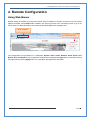
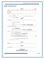
1
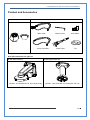
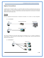
Hunt Electronic Inc HTP‐T2M20WXI 2.0 Megapixel IP PTZ Camera X20 Zoom CMOS User Manual ver.2.0 2.0 Megapixel IP X20 PTZ Camera User Manual Safety Precaution We appreciate your purchasing Megapixel IP PTZ camera. Before installing the product, please read the following with care. Make sure to turn off the power before installing camera. Do not install under the direct sunlight or in dusty areas. Make sure to use the product within the temperature and humidity specified in the specification. Do not operate the product in presence of vibrations or strong magnetic fields. Do not put electrically conducting materials in the ventilation hole. Do not open the top cover of the products. It may cause a failure or electric shock on the components. To prevent from overheating, make sure to keep the distance at least 10cm from the ventilation hole. Make sure proper voltage before connecting the power. 2/67 2.0 Megapixel IP X20 PTZ Camera User Manual Table of Content 1. Introduction .......................................................................................................................... 4 About this manual ............................................................................................................... 4 Features ............................................................................................................................ 4 Product and Accessories...................................................................................................... 6 Part Names and Functions .................................................................................................... 7 System Connections ............................................................................................................ 8 2. Installation .......................................................................................................................... 10 DIP Switch Setup .............................................................................................................. 10 Installation Camera with Brackets ........................................................................................ 12 Wiring/Cabling & Connecting .............................................................................................. 14 Check if it works ............................................................................................................... 17 3. System Operation ................................................................................................................ 18 Remote Video Monitoring ................................................................................................... 18 Initialization of IP address ................................................................................................... 21 4. Remote Configuration .......................................................................................................... 22 Using Web Brower ............................................................................................................. 22 System Configuration ......................................................................................................... 23 Video Configuration ........................................................................................................... 27 Audio Configuration ........................................................................................................... 32 Network Configuration........................................................................................................ 34 Serial Configuration ........................................................................................................... 40 Event Configuration ........................................................................................................... 43 PTZ Configuration ............................................................................................................. 49 Record Configuration ......................................................................................................... 54 User Configuration ............................................................................................................ 61 Camera Configuration ........................................................................................................ 63 3/67 2.0 Megapixel IP X20 PTZ Camera User Manual 1. Introduction About this manual This User Manual provides information on operating and managing the megapixel IP PTZ camera. The Manual includes instructions of installation, operation and configuration of megapixel IP PTZ camera as well as how to make troubleshooting. Features This product is a megapixel PTZ network-based camera with remote live monitoring, audio monitoring and control via an IP network such as LAN, ADSL/VDSL, and Wireless LAN. Video z Highly efficient compression algorithm, H.264 & MJPEG support z Wide range of transmission rates: 32kbps ~ 10mbps z Various transmission modes: CBR, VBR z Motion detection Audio z Multi-transmission mode: Simplex (IP PTZ camera Æ Client PC or Decoder, Client PC or Decoder Æ IP PTZ camera), Full Duplex Network z Fixed IP & Dynamic IP (DHCP) support z 1:1, 1:N support z Multicasting z Various types of Protocol support : TCP/IP, UDP, Multicast, DHCP, SMTP, HTTP, SNMP, RTP, RTSP z ONVIF, PSIA compliant Serial Data z RS-485 support z Data pass-through mode : Serial data communication between megapixel IP PTZ camera and Decoder Sensor and Alarm z Support direct connections of external sensor and alarm devices z Event Alarm notification. z If an external sensor is activated, camera can be set to move to the corresponding Preset position. 4/67 2.0 Megapixel IP X20 PTZ Camera User Manual User Interface z Diagnose and upgrade through dedicated program called True Manager z System configuration using Internet Explorer High Reliability z Reliable embedded system Powerful Pan/Tilt Functions z Max. 360°/sec high speed Pan/Tilt Motion z Using Vector Drive Technology, Pan/Tilt motions are accomplished in a shortest path. As a result, time to target view is reduced dramatically and the video on the monitor is very natural to watch. z For jog operation using a controller, since ultra slow speed 0.05°/sec can be reached, it is very easy to locate camera to desired target view. Additionally it is easy to move camera to a desired position with zoom-proportional pan/tilt movement. Preset, Pattern, Swing, Group z MAX. 128 Presets are assignable and characteristics of each preset can be set up independently, z Max. 8 set of Swing action can be stored. This enables to move camera repetitively between two preset positions with designated speed. z Max. 4 of Patterns can be recorded and played back. This enables to move camera to follow any trajectory operated by joystick as closely as possible. z Max. 8 set of Group action can be stored. This enables to move camera repetitively with combination of Preset or Pattern or Swing. A Group is composed of max. 20 entities of Preset/Pattern/Swings. PTZ(Pan/Tilt/Zoom) Control z With RS-485 communication, max. 255 of cameras can be controlled at the same time. z Pelco-D or Pelco-P protocol can be selected as a control protocol in the current version of firmware.. Easy Installation and Perfect Outdoor Environment Compatibility z Fans and heaters are built-in in camera for cold and hot temperature environment. Also idealistic mechanical design protects camera from water and dust z It is easy to install and maintain camera with terminal for cable connection in brackets. 5/67 2.0 Megapixel IP X20 PTZ Camera User Manual Product and Accessories z Main body & Dome Cover z Accessories Main Cable Cross LAN Cable Wrench Driver 2EA of BNC Audio Cable CD Note: Mount Brackets are optional. z Wall Mount Bracket [Screws : Torx Secrew M4×18, Hex Lag #14×50] z Ceiling Mount Bracket [Screws : Torx Screw M4×18, Anchor Bolt 3/8"×70] 6/67 2.0 Megapixel IP X20 PTZ Camera User Manual Part Names and Functions ① • Dome Cover Do not detach protection vinyl from dome cover before finishing all installation process to protect dome cover from scratches or dust. • DIP Switch Sets up camera ID and protocol. • Drop Prevention Spring This part keeps the camera from dropping during installation and maintenance. After install the Bracket, please, hang the spring to the drop prevention hook of main body as shown in picture for further tasks. • Mounting Screw Hole This hole is for screws that assembles the main body with a bracket. • IP Reset Switch Reset its network configuration to the factory defaults. You will lose all data that had been entered previously. To initialize the system to the factory default, press the reset button for more than 5 seconds. • LAN Port Used for the Ethernet connection • Audio Port Used for the audio in/out connection. • Video (BNC) Used for the composite video out or HD-SDI video out connection according to models • Main Connector Used for the power wire, the RS-485 communication cable, alarm in/out connection cable. 7/67 2.0 Megapixel IP X20 PTZ Camera User Manual System Connections IP Camera can be connected in either 1 to 1 connection where one camera is connected to one PC client or a decoder system or 1 to many connections where one camera can be connected to several PCs and decoder systems. (video server can work as a video decoder which takes the data from a video server or IP camera, decodes and outputs analog video.) Topology Generally, megapixel IP Camera and PC or a decoder is connected in 1-to-1 mode or 1-to many configuration. z 1:1 Connection . Site Remote Center (Decoder) Site Remote Center Remote Center (PC SW) One camera is installed at a site where video images are transmitted. A PC or a decoder is installed at a central location to receive and view the video images on an analog monitor. Audio and serial data are transferred in either direction. z 1:N Connection . Site Remote Center or or or 8/67 2.0 Megapixel IP X20 PTZ Camera User Manual In this configuration, a site can be monitored from many remote central locations. Although up to 64 PCs or decoders can be connected to one camera, in the real network environment, network bandwidth can limit the maximum connections. Functionally, the central monitoring system (CMS) software provided can replace the decoder. Multicast Mode If the network supports multicasting, a large number of decoders can be used to receive video effectively from a camera using a single streaming of video and audio. However, multicast mode is possible only when network environment supports multicast. Relay Center 1(Decoder) Site Center 2 (Decoder) Video and audio data can be retransmitted from a center to another center. The arrangement is useful when the network bandwidth to the site is limited while there are more than one center want to monitor the site. VMS (Video Management System) Site Site Remote Center Remote Center (Decoder) CMS VMS (Central Monitoring System) is a Window-based remote monitoring program in order to monitor or control video, audio, and events in real time from several IP cameras or video servers. Please refer to the VMS User Manual for more in detail. 9/67 2.0 Megapixel IP X20 PTZ Camera User Manual 2. Installation DIP Switch Setup When you control the camera through RS-485, before installation, you should set the DIP switches to configure the camera ID, communication protocol. Camera ID setup z ON ON ID numbers of camera are set up with binary numbers.. See the examples shown below 1 2 3 4 5 6 7 8 Pin 1 2 3 4 5 6 7 8 ID Value 1 2 4 8 16 32 64 128 ex) ID=5 on off On off off off off off ex) ID=10 off on Off on off off off off z The camera ID range is 1~255. Camera ID must not be 0. z Factory default of Camera ID is 1. z Match the camera ID with Cam ID setting of your DVR or Controller to control the camera. 10/67 2.0 Megapixel IP X20 PTZ Camera User Manual Communication Protocol Setup z ON ON 1 Select the appropriate Protocol with DIP switch combination. Switch State 2 3 4 P0 (Pin 1) P1 (Pin 2) P2 (Pin 3) Protocol/Baud rate OFF OFF OFF PELCO-D, 2400 bps ON OFF OFF PELCO-D, 9600 bps OFF ON OFF PELCO-P, 4800 bps ON ON OFF PELCO-P, 9600 bps Otherwise z Reserved If you want to control using DVR or P/T controller, their protocol must be identical to camera. Otherwise, you can not control the camera. z Adjust the DIP switch after turning off the camera. If you changed the camera protocol by changing the DIP switch, the change will be effective after you reboot the camera. z Factory default of protocol is “Pelco-D, 2400 bps”. 11/67 2.0 Megapixel IP X20 PTZ Camera User Manual Installation Camera with Brackets Installation using Ceiling Mount Bracket ① Remove the ceiling tile from the ceiling and cut a hole whose diameter is 30~40mm on the ceiling tile to pass the wire(s) and cable(s) through to the upside of the ceiling. (In case of the wiring and cabling through the mounting surface only) Then prepare the ceiling mount bracket. Pull the wire(s) for the system as below. (Anchor Bolt 3/8"×70) ② Hook up “Drop Prevention Spring” on main body ③ Line up the mold lines and assemble main body to mount adaptor and turn it. And assemble the main both with the camera mount adaptor with the screws. (Torx screw M4X18). Please make sure the screws are tightly assembled for waterproof. ④ Screw the dome cover to the main body and remove the protection vinyl from the dome cover. to prevent camera from unexpected drop and pull the wire(s) and cable(s) for the system as below Notice z Before starting the installation, make sure that the Camera ID and Protocol are set up properly. z To adjust the installation height from the mounting surface, the pipe and coupler should be needed between the surface mount part of the ceiling mount bracket and the camera mount part of the ceiling mount bracket. Note that they are not supplied by the manufacturer. 12/67 2.0 Megapixel IP X20 PTZ Camera User Manual Installation using Wall Mount Bracket ① Make a hole whose diameter is 30~40mm on the mounting surface to pass the wire(s) and cable(s) through the mounting surface. (In case of the wiring and cabling through the mounting surface only) Then prepare the wall mount bracket. Pull the wire(s) and cable(s) for the system as below. Attach the wall mount bracket to the mounting surface. (Hex Lag #14×50) ② Hook up “Drop Prevention Spring” on main body to ③ Line up the mold lines and assemble main body to prevent camera from unexpected drop and pull the wire(s) and cable(s) for the system as below. ④ Screw the dome cover to the main body and mount adaptor and turn it. And assemble the main remove the protection vinyl from the dome both with the camera mount adaptor with the screws. cover. (Torx screw M4X18). Please make sure the screws are tightly assembled for waterproof. Notice z Before starting the installation, make sure that the Camera ID and Protocol are set up properly. 13/67 2.0 Megapixel IP X20 PTZ Camera User Manual Wiring/Cabling & Connecting Port Description z Main Cable Port Pin Number (RJ45) Connector / Wire Color Signal 1 Black RS485 + 2 Brown RS485 − 3 Red DC 12V 4 Orange Ground 5 Yellow OUT COM (Relay Output Common) 6 Green OUT 2 (Relay Output 2) 7 Blue OUT 1 (Relay Output 1) 8 Violet IN COM (Sensor Input Common) 9 Gray IN 1 (Sensor Input 1) 10 White IN 2 (Sensor Input 2) Port Pin Number Connector/ Wire Color Signal 1 RCA (Yellow) Audio IN z Audio Cable 2 3 Audio GND RCA (White) Audio OUT 14/67 2.0 Megapixel IP X20 PTZ Camera User Manual Connecting Power 1. Carefully check the voltage and current capacity of the rated power. The rated power is indicated in the back of main unit. 2. After confirming the power source, connect power adaptor and connect the 12V DC connector to the system z For the DC input models, be careful with the polarity of DC power. The system should be permanently damaged by wrong DC input. z In case that the length of the power wire is very long, there may be voltage drop and the system may not work properly. Make the length of the power wire as short as possible. Connecting Network 1. Plug network cable to Ethernet port (RJ-45 network port). Connecting Video 1. To display video through the composite or HD-SDI port, connect each port to a monitor using BNC coaxial cable 2. Set Enable Preview option “ON” on the Video tab of web page. (Please refer to the Video Configuration part) z Especially in case of using HD-SDI, video cannot be viewed if BNC coaxial cable is not used. z In case that video transmission distance is long, video data may not be transmitted due to a reduction in the video signal. In order to prevent it, install a repeater in the middle. z In case of using HD-SDI, video can be viewed only on a HD-SDI monitor. Connecting Audio Audio is full-duplex. It is possible to set the mode as Tx-only, Rx-only or Tx-Rx. 1. Connect audio input and output ports to audio devices accordingly. 2. The Audio signal required is line level, so an audio equipment with an amp, mixer or other amplifier should be used. 15/67 2.0 Megapixel IP X20 PTZ Camera User Manual Connecting Serial Port (RS-485 Communication) z For PTZ control, connect the cable(s) to your keyboard or DVR. To connect multiple cameras to a single controller, RS-485 communication should be connected in parallel as shown below. If you are connecting a single camera to a controller, terminate the camera. When connecting more than one camera to a single controller, terminate the last camera on the communication line. The last camera means the camera farthest in cable length from the controller. Note that the total length of the communication cable between a controller and the camera(s) on the same communication line must be less than 1.2Km. z RS-485 of Megapixel PTZ Camera can be connected to external equipment such as PT receiver etc. PC client can send PT commands to the external equipment via the serial port. When a decoder system instead of PC client is connected to Megapixel PTZ Camera, the serial port and that of the decoder system works in pass-through mode. That is, data from at one port is delivered to the other port, vice versa Connecting Sensor and Alarm Connect sensor and alarm devices to corresponding terminals accordingly. z Sensor Input V+ IN 1 Sensor 1 IN 2 Sensor 2 IN COM 16/67 2.0 Megapixel IP X20 PTZ Camera User Manual z Relay Output Internal AC or DC OUT COM OUT 1 LOAD OUT 2 LOAD Maximum allowable electrical load of relay is shown bellow table. Drive Power DC Power AC Power Max. Load Max DC 24V, 1A Max AC 125V, 0.5A Check if it works Once the power is supplied to the camera, it will start booting. The system will boot up to an operating mode after approximately 40-60 seconds. The green LED on the Ethernet port will flash indicating the system is ready. The software provided in the CD called True Manager allows you to check the IP address and other network details of the camera. Please refer to the True Manager manual for instructions on how to find the IP address of the camera and change it if required. 17/67 2.0 Megapixel IP X20 PTZ Camera User Manual 3. System Operation Remote Video Monitoring There are two ways to monitor video when the center system and Megapixel PTZ Camera are connected. In order for a proper operation, an IP address must be set accordingly. Please refer to True Manager in Chapter 3 or Remote Setting in Chapter 4 for further details. Default ID : admin Default Password : 1234 . Video Monitoring using Internet Explorer Open Internet Explorer and enter camera’s IP address. The system will ask for confirmation to install Active-X control. Once authorized, the Internet Explorer will start to display video images from camera as shown below. Default IP Address : http://192.168.10.100 18/67 2.0 Megapixel IP X20 PTZ Camera User Manual z Video Select Select the Video stream to be viewed: Primary or Secondary This camera is capable of dual streaming; primary streaming and secondary streaming. Video will be displayed according to the resolution set on video configuration. If dual streaming (“Use Dual Encode” Menu in Video page) is not activated, secondary video is not available z View Size Adjust the Screen size Screen size is initially adjusted according to the compression resolution. If you click 50% icon, the whole screen size will be reduced to half size. z Digital Zoom Control the Digital zoom on the screen The more the camera zooms in, the smaller the square of control panel is. Position of the image can be changed by moving position of the square. If you press x1, the screen will return to the normal size. z PTZ Control (Optical Zoom & Digital zoom built-in the camera) Control PTZ and PTZ Control Panel is used for controlling external PTZ devices when the external PTZ devices are connected through serial port. It is possible to make zooming control by Zoom in/out buttons of PTZ control Panel (In order to use digital zoom, select Digital zoom ON in the Camera tab) - Stop Stop on-going PTZ action. - Focus Near, Focus Far, Auto Focus Adjust the focus of the lens z Select Preset Set preset position and move to the specific preset position. - Goto: Move to the selected preset entry if the preset entry is set. - Set: Set the current position to the selected preset entry. - Clear: Delete the selected preset entry. z Select List Run a selected Pattern or Swing or Group. After selecting an entry in the list, Pattern, Swing or Group button can be pressed. Then, corresponding operation is executed for the selected list. (Please refer to the PTZ tab to set Pattern, Swing and Group) 19/67 2.0 Megapixel IP X20 PTZ Camera User Manual z Sensor Input Display the status of the sensor in real time. This camera supports two sensor inputs. When the sensor of the camera is working, the sensor light turns red. z Alarm Output Operate the alarm device by pressing the number icon This camera supports two alarm outputs. A number icon indicates status of the alarm device. z Snapshot Capture video images and store them as BMP or JPEG files. z Talk Transfer audio from PC’s mic to the camera. z File Record Recording to an AVI file on Live View page is available. AVI files are generated in the specified folder or in specified file name on the PC where web browser is running. 1. Press “Set” button to select folder or create a new folder. Enter the file name on Filename field. 2. Press “Start” button to start to record. 3. Press “Stop” button to stop to record. 4. AVI file named “IP address_hh_mm_ss” or “File name_IP address_hh_mm_ss” will be generated in the specified folder depending on whether the path specified a folder or a prefix of the file name. z Display Buffer Set the number of video frames to be buffered before being displayed on web browser. Larger value results in smoother video by sacrificing the latency. A setting of 10 ~ 15 frames can be used generally for most situations. z Other key function - Click to Center On-screen PTZ control TCAM-570 series support “Click to center” as a function of on-screen PTZ control. By double clicking a position on the video area of web viewing, it is possible to move the clicked position to the center of the video area and zoom in. 20/67 2.0 Megapixel IP X20 PTZ Camera User Manual Video Monitoring with Decoder System Once camera’s IP address is set in the remote IP address section of the decoder, the decoder system will connect to camera and start receiving the video images. Normally, a monitor connected to the decoder will display video images Initialization of IP address If a system IP address is lost, the system can be reset to the system default IP address using the reset button in the back side of the system. 1. While system is in operation, press the reset button for more than 5 seconds. 2. The system will reboot automatically 3. Once the system reboots, IP address will be set to the system default as below. • IP mode Fixed IP • IP address 192.168.10.100 • Subnet mask 255.255.255.0 • Gateway 192.168.10.1 • Base port 2222 • HTTP port 80 21/67 2.0 Megapixel IP X20 PTZ Camera User Manual 4. Remote Configuration Using Web Brower Remote setting is available by using web browser. Enter IP address of camera and then a live view screen appears as below. Press Setup button located in the upper right area of the monitoring screen to go to the server setup. For Remote Setting, user should be authorized higher than manager level. c Enter IP Address d Press Setup button The configurations are grouped into 10 categories: System, Video, Audio, Network, Serial, Event, PTZ, Record, User and Camera. Any configuration changes are not applied until Apply button is pressed. Leaving the page without pressing Apply button, any changes in the page will be discarded. 22/67 2.0 Megapixel IP X20 PTZ Camera User Manual System Configuration 23/67 2.0 Megapixel IP X20 PTZ Camera User Manual General z System ID Enter System ID that is used as a camera title The set System ID is displayed with video image on Web browser. The System ID is also transferred to remote software, such as VMS, and displayed on it. z Burnin OSD System ID Burnin OSD System ID specifies the string to be inserted into video image before encoding. Only alphanumeric and blank characters are allowed. Position and size can be configured on Burnin OSD section of Video page. z Language Select the language to be used for web-based configuration Firmware z Firmware version Display the current firmware version z Board ID Display the Network board ID of the camera recognized by system z Upgrade Upgrade firmware 1. Press Browse button to select a firmware file from PC. 2. Press Firmware Upgrade button to start to upgrade. 3. Messages for showing status (downloading / upgrading) will be displayed. 4. The camera will reboot automatically after completing upgrade. Do not turn the camera off during upgrading 24/67 2.0 Megapixel IP X20 PTZ Camera User Manual Config Backup & Restore z Backup All the setting of configuration can be stored. z Restore Stored configuration can be browsed and restored. The server is rebooted once Config Restore button is pressed. Time z Start Time The latest the camera’s booting date and time z Current Time Current date & time Enter a new date and time and press Set Current Time button to update date & time z Time Format Change the time format. Selectable time formats are as below - YYYY/MM/DD hh:mm:ss (Ex. 2010- 4-11 18:18:42) - DD/MM/YYYY hh:mm:ss (Ex.11- 4-2010 18:18:42) - MM/DD/YYYY hh:mm:ss (Ex. 4-11-2010 18:18:42) z Time Zone Select time zone of where the camera is installed. Depending on the time zone, Daylight Saving Time will work automatically A time zone is a region of the earth that has uniform standard time, usually referred to as the local time. By convention, time zones compute their local time as an offset from UTC (Coordinated Universal Time). In casual use, GMT (Greenwich Mean Time) can be considered equivalent to UTC. Local time is UTC plus the current time zone offset for the considered location . 25/67 2.0 Megapixel IP X20 PTZ Camera User Manual z Automatically synchronize with NTP server Synchronize the camera time with an NTP server using NTP (network time protocol). Name of the NTP server should be registered on NTP server Name. The Network Time Protocol (NTP) is a protocol for synchronizing the clocks of computer systems over packet-switched, variable-latency data networks. It is designed particularly to resist the effects of variable latency by using a jitter buffer. Reboot z Reboot the camera. Do not press the Reboot button unless the server needs a reboot. Factory Reset z All settings including user accounts and logs are cleared. Factory Reset except network settings z All the settings except for current network settings are changed to default values. 26/67 2.0 Megapixel IP X20 PTZ Camera User Manual Video Configuration 27/67 2.0 Megapixel IP X20 PTZ Camera User Manual Encode z Enable Preview 1. Select ON to enable to display video on the monitor that is connected to the composite or HD-SDI video port. 2. Select the Output format accordingly in the end of the Video page. Note that when Enable Preview is ON, dual streaming is not available. When the video is transmitted directly to the monitor through BNC cable, the video does not go thorough network and encoding. Therefore, there is less delay and no an effect from network limitation. z Resolution Select video encoding resolution. Scaling option is used when encoding resolution is different from input resolution. Without Scaling option, input video will be cut according to encoding resolution. On the other hand, if Scaling is selected, input video will be adjusted according to encoding resolution. z Framerate Determine the maximum number of frames per second for the video stream. 1,2,3,4,5,6,8,10,15,20,25 and 30 frame rate can be selected. The actual frame rate of video can be less than the maximum frame rate set due to the network bandwidth limitation z Preference Select encoding mode to control video quality or bitrate: Quality(VBR) or Bit rate(CBR). If ‘Bitrate’ selected, the video encoding will be effected by the ‘Bitrate’ value entered. Therefore, “Bitrate” mode corresponds to CBR (Constant Bit rate) encoding. If ‘Quality’ selected, the video encoding will be effected by the quality of image selected. Therefore, “Quality” mode corresponds to VBR (Variable Bit Rate) encoding. z Quality Select Video quality. 7 levels of quality are available. Quality mode (VBR encoding) tries to encode every frame in a constant quality. Therefore, resulting bitrate may vary a lot depending on the complexity or activity changes in the input video. It is preferred when constant video quality is required and network bandwidth is enough for delivering the stream of highly varying bitrate. 28/67 2.0 Megapixel IP X20 PTZ Camera User Manual z Bit rate Determine bitrate value between 32 ~ 8000kbps. Bitrate mode (CBR encoding) allows you to set a fixed target bitrate that consumes a predictable amount of bandwidth. In order to keep the bitrate limit, video quality is controlled dynamically according to the complexity or activity changes in the input video. z I-Frame Interval Determine I-frame Interval between 1 and 255. z H.264 Profile Select H.264 Profile: High Profile or Baseline Profile The standard defines various sets of capabilities, which are referred to as profiles, targeting specific classes of applications. z High Profile (HiP) The primary profile for broadcast and disc storage applications, particularly for high-definition television applications (for example, this is the profile adopted by the Blu-ray Disc storage format and the DVB HDTV broadcast service). z Baseline Profile (BP) Primarily for low-cost applications that require additional data loss robustness, this profile is used in some videoconferencing and mobile applications. This profile includes all features that are supported in the Constrained Baseline Profile, plus three additional features that can be used for loss robustness (or for other purposes such as low-delay multi-point video stream compositing). Dual Encode z Use Dual Encode 1. Select Off button on the Enable Preview to enable to use Dual Encode 2. Select ON to enable to use Dual Encoding The secondary video can be viewed on Live View window by selecting Secondary on Video selection z Dual Encode Algorithm Select H.264 or MJPEG for the secondary streaming. In case of H.264, either Bitrate mode or Quality mode can be selected for Preference mode in. On the other hand, MJPEG supports Quality mode only. 29/67 2.0 Megapixel IP X20 PTZ Camera User Manual Motion Detection z Use Motion Detection Determine to use Motion Detection function z Motion Detection on PTZ Allow disabling of motion detection when PTZ operation is performed. When it is set to Disable, motion detection is disable while the scene is changed due to PTZ control. z Motion Detection Area Editing Configure regions for motion detection. Regions of arbitrary shape can be configured by the following steps. c Select Enable on Edit tab d Select editing Mode. Set is for including cells to motion detection region and Erase is for excluding. e Select cells using the right button of the mouse. Multiple cells can be selected conveniently by press and dragging. f Press Apply Edited Area to save the editing z Sensitivity Sensitivity is the condition to trigger an event of motion detection. The value determines the sensitivity of the motion detection within a block: the smaller, the more sensitive. It is selectable from 0 to 10. Information Display System ID and/or server time can be display over the video window in Internet Explorer. Each item can be turn on or off separately, and position also can be configured. This information is displayed after the video is decompressed. 30/67 2.0 Megapixel IP X20 PTZ Camera User Manual BurnIn OSD Insert system ID and date/time in the compressed video. System ID and time respectively can be turned on or off in the video. Position and Font size can be configured also. System ID for BurnIn OSD exists independently from normal System ID. Note that size of Burnin OSD display varies according to the encoding resolution setting. This is inevitable because Burnin OSD is inserted to the frames before encoding is performed. The following table describes the rule for BurnIn OSD display. Resolution Small (8x8) Middle (16x16) Large (32x32) 352x480 / 352x240 / 352x576 / 352x288 2 1 0 720x480 / 720x240 / 720x576 / 720x288 / 2 2 1 2 2 2 640x480 / 800x600 1024 x 768 / 1280x720 / 1280 x 960 / 1280x1024 / 1440x900 / 1600x900 / 1680x1050 / 1920x1056 / 1920x1080 / 2048x1536 / 2560x1600 / 2592x1936 2 : Both System ID and Time are displayed 1 : Either System ID or Time can be displayed. When both are enabled, System ID is displayed. 0 : No items are displayed. This is because video area is too small to display OSD text in large text. Output Format Output Format menu appears only when Enable Preview is on. Select the output format for the monitor preview according to the video output and monitor specification. 31/67 2.0 Megapixel IP X20 PTZ Camera User Manual Audio Configuration Algorithm z Algorithm Select the audio algorithm: G.711 or AAC G.711 and AAC from client to server direction are supported. Thus, bidirectional audio communication is supported. z Bit rate Select the bitrate between 64Kbps and 128kbps when AAC is selected The sampling rate is fixed to 8KHz and 32KHz for G.711 and AAC respectively. Note that when camera is connected to a decoder, the decoder’s audio algorithm should be set identically to transmit audio properly. Mode z Select audio operation mode Mode Action Off No operation Tx-Only Transmit only Rx-Only Receive only Tx & Rx Transmit and Receive 32/67 2.0 Megapixel IP X20 PTZ Camera User Manual Input Gain z Set audio input gain from 0 to 31. Audio Output Configure the audio source to be played on audio output port. z Decoded Audio: Audio stream from client is played. z Loopback: Audio data from audio input port is loop-backed to the audio output port. 33/67 2.0 Megapixel IP X20 PTZ Camera User Manual Network Configuration 34/67 2.0 Megapixel IP X20 PTZ Camera User Manual Local z IP mode Select the IP mode: Fixed IP or DHCP (Dynamic Host Configuration Protocol) Depending on the selected mode, further configuration items come as follows IP Mode Selection Local IP Fixed IP Local Fixed IP address Gateway IP address Gateway Local Subnet DHCP Description Subnet mask N/A Please ask IP address information from ISP provider or network manager. DNS z Obtain DNS server address automatically Get DNS server address automatically when IP mode is DHCP. z Use the following DNS server addresses Enter the DNS server IP address. z Primary DNS server z Secondary DNS server Domain Name System (DNS) is a database system that translates a computer's fully qualified domain name into an IP address. Networked computers use IP addresses to locate and connect to each other, but IP addresses can be difficult for people to remember. For example, on the web, it's much easier to remember the domain name www.amazon.com than it is to remember its corresponding IP address (207.171.166.48). Each organization that maintains a computer network will have at least one server handling DNS queries. That server, called a name server, will hold a list of all the IP addresses within its network, plus a cache of IP addresses for recently accessed computers outside the network. Ipv6 z Ipv6 Address Enter the designated Ipv6 address. z Ipv6 Subnet Prefix Length Enter the bit number of Ipv6 Subnet. z Ipv6 Default Gateway Enter the designated Ipv6 gateway. z Ipv6 Link Local Display Ipv6 Link Local. 35/67 2.0 Megapixel IP X20 PTZ Camera User Manual Port z Base Port (1025 ~ 65535) Enter the Base Port number. Network base port is use for communication with remote clients. In order for camera and remote systems (decoder or VMS, NVR software) to be connected, the port number must be identically configured in camera side and client side. z HTTP Port (80, 1025 ~ 65535) Enter HTTP port used for web-based connection z HTTPS Port (443, 1025 ~ 65535) Enter HTTPS port used for secured HTTP connection. z RTSP Port (554, 1025 ~ 65535) Enter RTSP port used for RTSP-based connection. The default RTSP port is 554 RTSP (Real Time Streaming Protocol) is a standard for media streaming between server and client. Discovery z UPNP By setting UPNP to ON, it allows the discovery by the client according to UPNP (Universal Plug and Play) protocol. z Zeroconf By setting Zeroconf to ON, it allows the discovery by the client according to Zeroconf protocol. z WS Discovery Discovery function based on web service is enabled. It allows the discovery by Client SW which is supporting ONVIF. Authentication z RTSP Authentication If RTSP Authentication set to ON, user in the client side is asked to enter User ID and Password. z HTTP API Authentication When HTTP API authentication set to ON, HTTP Authentication is asked for all clients which use HTTP API . One-way Streaming z This IP camera provides two kinds of one-way(unidirectional) streaming based on UDP to clients: RTP and MPEG-TS. Both are a kind of broadcasting where traffic from client to server is not generated at all. 36/67 2.0 Megapixel IP X20 PTZ Camera User Manual z RTP (Real-Time Transport Protocol) is an Internet protocol used for transmitting single real-time multimedia data such as audio and video to a select group of connected clients. Normally RTSP uses RTP to format packets of multimedia content. RTP menu is used when the RTP only streaming without RTSP connection. RTP stream will be transmitted to the destination set. The SDP (Session Description Protocol) file can be found in the server, and a client can retrieve it using http connection. Related settings are as follows: - Destination IP : Set the IP Address of the destination system which will receive RTP stream If the system is decoder, RTSP authentication information can be entered in the middle of RTSP URL as follows: rtsp://admin:[email protected]:554/video1 - Destination Port : Set the Port of the destination system which will receive RTP stream - User Name: Enter the User name that will be used as session name in the SDP file. - File Name: Enter the file name that will be used as the name of the SDP file. Then, it can be accessed through http://ServerAddress/filename z MPEG-TS is a standard format for transmission and storage of audio, video, and data,[7] and is used in broadcast systems such as DVB and ATSC. Transport Stream is specified in MPEG-2 Part 1, Systems (formally known as ISO/IEC standard 13818-1 or ITU-T Rec. H.222.0). Transport stream specifies a container format encapsulating packetized elementary streams, with error correction and stream synchronization features for maintaining transmission integrity when the signal is degraded. As MPEG-TS itself supports only AAC as the audio algorithm, only video is streamed when audio algorithm is set to G.711. Related settings are as follows: - Destination IP : Set the IP Address of the destination system which will receive MPEG-TS stream - Destination Port : Set the Port of the destination system which will receive MPEG-TS stream 37/67 2.0 Megapixel IP X20 PTZ Camera User Manual SNMP Setup for using SNMP (Simple Network Management Protocol). It is compatible to both SNMPv1 and SNMPvec. Settings for using SNMP (Simple Network Management Protocol) are as following z SNMP Listen Port(0, 161, 1025 ~ 65535): The port is for connecting external devices when system operates as a SNMP client. SNMP is not used by setting 0 value. z SNMP Trap Destination IP: Set the SNMP Trap Destination IP. z SNMP Trap Destination Port (0, 162, 1025 ~ 65535): Set the SNMP Trap Destination Port. SNMP is not used by setting 0 value. Simple Network Management Protocol (SNMP) is used by network management systems to communicate with network elements. SNMP lets TCP/IP-based network management clients use a TCP/IP-based internetwork to exchange information about the configuration and status of nodes. SNMP can also generate trap messages used to report significant TCP/IP events asynchronously to interested clients. For example, a router could send a message if one of its redundant power supplies Multicast z Multicast IP The Multicast menu is used for configuring the multicast IP address to which media stream is delivered when a client such as a Decoder, VMS or NVR software is connected in multicast mode. The multicast IP address selection range is between 224.0.0.0 and 239.255.255.255. The selection can be used only when media protocol is set to Multicast. DDNS Select the DDNS (Dynamic DNS) server to use. One of the two servers can be selected. z True DNS: TrueDNS service is used in this mode. Systems can be registered on the website for TrueDNS service: http://ns1.truecam.net. System will get a domain name of xxx.truecam.net style. Please refer to user guide document for True DNS service. z DynDNS: DynDNS service is used in this mode. Refer www.dyndns.org for details. ID, Password and Domain name are needed when DynDNS is set. Dynamic DNS is a method, protocol, or network service that provides the capability for a networked device, such as a router or computer system using the Internet Protocol Suite, to notify a domain name server to change, in real time (ad-hoc) the active DNS configuration of its configured hostnames, addresses or other information stored in DNS. z Vdyn: Vdyn is a DDNS service provided by Visionica (http://visionica.com). No further configuration is required for using this service. It internally uses MAC address for the registration. When it succeeds, the domain name of the form 001C63A607EC.visionica.info is displayed on CurrentDomain entry of Network page. E-mail setting is not mandatory. 38/67 2.0 Megapixel IP X20 PTZ Camera User Manual z Check IP Disable: If “Check IP Disable” is selected, it will skip to check its own IP. In Fixed IP mode, the set IP will be registered on DDNS server. In DHCP mode, dynamically assigned IP will be registered on DDNS server. Normally Check IP Disable should be unchecked in order to obtain public IP in the network. Bitrate control When there are more than one client connected to the camera, due to bandwidth difference among the clients some of them do not have enough bandwidth to receive encoded stream completely. In this case, it is possible to select the way to stream video to clients as following. z Frame Drop Mode: Encoding is performed strictly according to video settings. When a client is connected through a network with less bandwidth, it may not receive all the frames. That is, frames are dropped on sending module if the network is bottlenecked. z Suppression Mode: Encoding bitrate and frame rate are adjusted not to drop any frames when the network bandwidths to some clients are limited. In this case, all clients can be affected by the averaged bitrate and frame rate. Address Information Followed network information is displayed (Read only) z IP Address: The Camera own IP address. This information is useful when the camera’s IP mode is set to DHCP. z Domain Name: In case the camera is registered at DDNS server, the registered domain name is displayed. z MAC Address: Display the MAC address of the camera. In case the camera is registered at DDNS server, the MAC address is used in DDNS registration. z Connecting: Client IP Addresses that are currently connected to system are listed. (1) Indicates 39/67 2.0 Megapixel IP X20 PTZ Camera User Manual Serial Configuration 40/67 2.0 Megapixel IP X20 PTZ Camera User Manual Serial Port Configuration z Serial Port Information This camera supports one RS-485 serial port The serial port of camera is configured with the DIP switch in the camera. Serial Port Information section just displays the information. DIP switch setting is effective only after the camera is rebooted. By default, Pelco-D protocol is used with 2400bps baudrate. Sensor Type z There is two sensor input ports on Megapixel PTZ Camera. The sensor port can be configured to the following. Function OFF NO (Normally Open) NC (Normally Closed) Operation Not used The port is normally open and activated when closed. The port is normally closed and activated when opened. The function of the sensor port is set based on the type of the sensor connected. Sensor Schedule z Choose Sensor OFF or Sensor ON and click the below schedule cells to make Sensor Schedule according to day of week and hour. z Click desired “Cell” to set schedule. z Click desired “Time Line or Date Line” to set schedule. 41/67 2.0 Megapixel IP X20 PTZ Camera User Manual z To set all cells in the schedule, click below “Empty Cell”. 42/67 2.0 Megapixel IP X20 PTZ Camera User Manual Event Configuration 43/67 2.0 Megapixel IP X20 PTZ Camera User Manual This camera has two sensor ports and two alarm ports. When a decoder instead of a PC client is connected to camera, one system becomes a Local system and the other a Remote system (Generally a system which is being used by the user is called as Local system). Then, actions for events can be configured for events from the remote system as well as for local system. For example, it is possible to turn on an alarm device in local (center) decoder system when a sensor device in remote (site) IP camera is triggered. Local section configures the actions for events from local (self) system, and configuration activates local devices and Remote sections configure the actions for events from remote (peer) system. The following table lists the possible actions for events. Action Description Alarm out Triggers alarm (relay) port. E-mail Sends E-mail to the specified address. AVI file can be attached FTP Upload AVI file to a specified FTP server Preset Move to the Preset position Local & Remote Event Configuration z Sensor Configure the actions when the sensor is activated. Multiple actions can be set for a single event. z On Video Loss Configure the actions when video input signal is lost. Multiple actions can be set for a single event. z On Motion Configure the actions when motion is detected. Multiple actions can be set for a single event. On Disconnect Configure the actions when the link (connection) with peer system is disconnected. Multiple actions can be set for a single event. Alarm and Beep activation duration Set the duration of alarm or beep activation in case of an event. If it is set to continuous, it will be in active state until the operator resets it manually. 44/67 2.0 Megapixel IP X20 PTZ Camera User Manual E-mail Notification Specify the information to send event information, when E-mail is selected as an event action. z Server Address Enter an address of mail(SMTP) server z Port Specify a port for SMTP operation (Port 25 is the default port in SMTP operation. If a different port is configured in the SMTP server, this port needs to be changed accordingly). z Sender Address Enter an account registered in the SMTP server. z Authentication on SMTP server This function is applicable when the E-mail server requires authentication for sending E-mail. z ID & password When the server requires authentication, ID and Password of an E-mail account need to be entered. z SSL This function is applicable when the E-mail server requires encryption for sending E-mail. z Destination address Enter Destination address. More than one address can be entered by delimiting comma (,) or semi-colon (;). Destination address can take up to 63 characters. z Video Clip Attaching Video clip stored at the moment of event can be attached as an AVI or JPEG file format. When dual encoding is enabled, Primary video, Secondary video(H.264 only) or JPEG Capture can be selected. The duration of video clip can be configured with Pre-Event Time and Post-Event Time in Event Record section.. z Number of Frame The number of JPEG frames is configured. This setting is applicable only when JPEG Capture is selected. z E-mail Test E-mail sending can be tested with this button. Please note that configured settings should be saved first by pressing Apply button before using E-mail Test function. One of the following messages will come as a result of the test. 45/67 2.0 Megapixel IP X20 PTZ Camera User Manual Message Description E-mail sent successfully Test E-mail has been sent successfully. Reception in the client can be checked. Failed to connect SMTP server Connection to the SMTP server failed. It is necessary to check if the server is reachable and server address and port are correct. Authentication failed The server is reachable but authentication failed. ID and/or password need to be checked. SMTP server rejected the mail The server is reachable, but mail sending failed due to a reason other than authentication. This error happens often when the server authenticates according to its own rule. For example, IP addresses of a specific range or addressed of a specific suffix are allowed. 46/67 2.0 Megapixel IP X20 PTZ Camera User Manual FTP Upload Specify the information to upload event information, when FTP is selected as an event action’ z Server Address Enter an address of an FTP server to receive video files z Port Specify a port for FTP operation (Port 21 is the default port in FTP operation. If a different port is configured in the FTP server, this port needs to be changed accordingly). z ID & password Enter ID and Password for accessing the FTP server.’ z FTP File name The names of files upload by FTP can be specified by user. If a fixed name is specified, the file is overwritten repeatedly. Max length of a file name is 60 characters. If the name is left blank, file name is determined according to the internal rule implemented in the firmware. The following macros are supported to form variable parts of file names. The strings are case-sensitive. %YYYY : year %MM : month %DD : day %hh : hour %mm : minute %ss : second %EVENT : event type (Sensor1, Motion, ...) %ADDR : address of the server (Domain name when DDNS is used. Otherwise IPaddress) “.avi” or “.jpg” will be added automatically at the end of the filename depending on the type of video file. z FTP Base Directory Specify the name of the directory to be created in the FTP server. It is valid only when Use Record is set to Use FTP on Record session z Upload video Primary Video and Secondary Video (H.264 only), JPEG Capture can be selected for uploading. The duration of video clip can be configured with Pre-Event Time and Post-Event Time in Event Record section. 47/67 2.0 Megapixel IP X20 PTZ Camera User Manual z Number of Frame Enter frame number of JPEG Capture (from 1 to 10). z Continuous Upload Continuous upload ‘On’ allows video clips to be transmitted regularly regardless of occurrence of events. When this mode is turned on, FTP upload by events is suppressed. z Upload Duration Specify recording duration of a video clip to be transmitted. (Max 300 sec). z Upload Interval Specify transmission interval. (Max 3600 sec). Upload Duration is not included in Upload interval. For example, if Upload interval is 60 seconds and Upload duration is 20seconds, a video clip for 20seconds is transmitted every 80 seconds. z FTP Test FTP upload function can be tested with this button. Please note that configured settings should be saved first by pressing Apply button before using FTP Test function. One of the following messages will come as a result of the test. Message Description FTP connection tested successfully The connection to the FTP server is successful. Failed to connect FTP server The connection to the FTP server failed. It is necessary to check if the server is reachable and server address and port are correct. Authentication failed The server is reachable but authentication failed. ID and/or password need to be checked.. Failed to upload file File upload failed. The user of the ID is not allowed for writing into the directory or FTP server can be full. Failed to erase file Failed to delete the test file. The user of the ID doesn’t have the privilege for file deletion. 48/67 2.0 Megapixel IP X20 PTZ Camera User Manual PTZ Configuration 49/67 2.0 Megapixel IP X20 PTZ Camera User Manual PTZ z Circular plate provides panning and tilting functions combined with speed control. Clicking a mouse on a position of the circular plate determines the speed of the control as well as the direction. Mask z Masks can be displayed in the video. 1. Position camera and select one of Masks from drop down menu. 2. Press New button to get a mask and adjust mask size with the size buttons . 3. The specified mark can be shown by Search button. Preset z Max 128 preset positions can be defined. z Select Preset Number: Select an entry in the list to be assigned to current camera position. z Focus Mode: Select the focus mode after preset Goto is executed. Do not change: current focus mode is not changed. Force Auto: auto-focusing is executed after the preset moved. Force Manual: move to the focus position saved when preset set. z Event Holding Time: Set the time to stay at the preset position when the preset moved by event. If it is set to 0, the camera doesn’t return to original position after moving to the preset position by event. z Edit Label: Assign a label to the preset position. Only the first 15 preset entries (Preset-1 ~ Preset-15) can have labels. Pattern z Pattern is a function that the camera memorizes the path (mostly curve path) by joystick of controller for assigned time and revives the path exactly as it memorized. 4 patterns can be defined and max 760 communication commands can be stored in a pattern. 1. Select one of the entries in Select Pattern Number list 2. Press Set Pattern Start button. Form the pattern by controlling PTZ. Every path will be saved until pressing Set Pattern Stop button 3. Press Set Pattern Stop button to save the pattern 4. Press Run Pattern button to run the selected pattern Notice : When the camera memorizes patterns, not the positions of pan/tilt/zoom but the commands are stored in the memory. Hence there might be small differences between the original path visited on forming the pattern and the revived path on running the pattern. 50/67 2.0 Megapixel IP X20 PTZ Camera User Manual Swing z By using swing function, you can make camera to move between 2 preset positions repeatedly. When swing function runs, camera moves from the preset assigned as the 1st point to the preset assigned as the 2nd point in CW(Clockwise) direction. Then camera moves from the preset assigned as the 2nd point to the preset assigned as the 1st point in CCW(Counterclockwise) direction. In case the preset assigned as the 1st point is same as the preset assigned as the 2nd point, camera turns on its axis by 360° in CW(Clockwise) direction and then it turns on its axis by 360° in CCW(Counterclockwise) direction. 1. Check Enable box 2. Select the Preset for 1st Position and 2nd Position 3. Enter the Speed (0~255) 4. Press Save Swing button to save the Swing 51/67 2.0 Megapixel IP X20 PTZ Camera User Manual Group z This function is that the camera memorizes the combination of Presets, Pattern and/or Swings sequentially and runs Presets, Pattern and/or Swings repetitively on activation. Max 8 groups are programmable. Each group can have max 20 actions which are the combinations of Preset, Pattern and Swing. Option field has different meanings for Preset and Pattern/Swing. For Preset, it configures the preset speed. For Pattern/Swing, it configures the number of repetition. Dwell time between actions can be set up as well. 1. Select one of the entries of Group 2. Press Modify Group button. The following window will appear. 3. Set Action(Preset or Swing or Pattern), Dwell Time and Option and click Enable squares 4. Press Apply button and the Group can be used on the Live View Page ☞ If a group includes an entry for which pattern or swing is not defined, nothing happens on the entry. However, Dwell time is applied for the entry even in such case. Ex) Group-1 Swing-1 Repeat 2 Preset-1 5 Speed 3 Pattern-1 10 Repeat100 3 52/67 2.0 Megapixel IP X20 PTZ Camera User Manual Using Pattern/Swing/Group in Live view page Pattern, Swing or Group which is configured on PTZ page can be activated in Live view page. 1. Select an entry in the list. 8 entries are valid for Swing and Group, while 4 entries are valid for Pattern. 2. Press the button for the function to activate. Auto Parking Auto parking is a function to return to the previous preset position or to resume operation such as Pattern, Swing or Group when a specified time expires after user stopped PTZ control. Parking time can be set from 0 to 3600 seconds and “0” means that Auto Parking function is turned off. 53/67 2.0 Megapixel IP X20 PTZ Camera User Manual Record Configuration 54/67 2.0 Megapixel IP X20 PTZ Camera User Manual DISK SD memory can be used, and at least 1GB size is recommended. Either EXT3 or FAT32 file system can be used. A disk with either EXT3 or FAT32 file system can be read in Linux PC. However, only disk with FAT32 file system can be read in Windows PC. Less than 4Mbps of video bit rate is recommended when you record and monitor video simultaneously since frame dropping may happen due to performance limitation. Disk information Be sure to restart the system after connecting an SD card. During booting, the system reads status of disk and initializes it. Once the initialization of a disk is finished, the status of disk is shown on Record page of web-based setup. Refer to the chart for checking the status of disk. Disk status Description Disk error detected Error No disk Disk is not connected to the system. Searching Disk information Checking the status of disk. Refresh the page and wait until the status is changed. Mounting and Performing recovery process when disk damage is found. It takes from seconds to minutes for recovering. Recovering Disk... Disk format needed Disk is attached, but the type of the file system is unknown or damaged. Unknown disk type detected USB Disk available Available to be used for recording Disk removed Disk is detached during operation or there is damage on the file system. If it happens while disk is connected, it is recommended to format the disk. or in abnormal state 55/67 2.0 Megapixel IP X20 PTZ Camera User Manual General z Use record - Off: Recording function will not be used when “Off” is selected - Use Disk: Recording will be enabled and data will be written to a disk - Use FTP: Recording will be enabled and data will be uploaded to an FTP server. In this mode FTP upload by event is automatically disabled. z Select Video Select video stream to record. z Manual Record When ON is selected, record is operated regardless of schedule. z Overwrite When the disk becomes full, the oldest data are deleted automatically. It is valid only when Use Record is set to Use Disk. z Max File Size/Max File Length Max File Size option is for limiting the size of AVI file. If small file size is set, files of small size will be generated but numbers of the files will be increased. Max File Length option is for limiting the time length of AVI file. If the size of a file becomes Max File Size or the duration of the recording reaches Max File Length, a new file is created. z Automatically Backup to FTP Data recorded in the disk can be uploaded to an FTP server automatically for backup. FTP server is configured on Event page. It is valid only when Use Record is set to Use Disk. z Erase After Backup Data are deleted in the disk automatically after being uploaded to the FTP server. It is valid only when Automatically Backup to FTP is used. z Start Time of Backup Data Specify the time of the data in the disk from which Backup to FTP Disk is performed. This time is changed automatically as the backup to FTP server goes. So it is useful to check current backup status. It is valid only when Automatically Backup to FTP is used. 56/67 2.0 Megapixel IP X20 PTZ Camera User Manual z FTP Base Directory Specify the name of the directory to be created in the FTP server. It is valid only when Use Record is set to Use FTP. Event Type Three recording modes are supported: Continuous, Event, Disconnect. In case of Event recording, event types can be selected among several events. Selected event type is used for configuring the schedule table. Up to 4 event types can be configured and each event type can be a combination of sensor, video loss and motion event. z Pre-event Time: Specify the duration of recording before an event happens. z Post-event Time: Specify the duration after the event is cleared. Schedule Table Actual recording mode is determined by Schedule Table, where recording mode configured by day (of a week) and hour. Each of recording mode configures the recording operation as follows: - Record off : No recording - Continuous : Records continuously - Disconnect: Recording is started when the system loses the connection to its last client(Decoder, VMS/NVR) etc. When there are multiple clients and one of the client is disconnected, this doesn’t happen. - Event Type: Records when an event configured in Event Type setting happens. Checking status of recording Recording status can be checked on the main view page. 57/67 2.0 Megapixel IP X20 PTZ Camera User Manual Search and Playback Recorded video and audio data can be saved as AVI format in the disk. In general, one AVI file is created for an event in case of event-based recording. However, it is possible that recorded data by serious of events happening continuously can be merged to a single AVI file depending on pre/post event time setting. The size of file is limited to 10 ~ 200MB or 10 minutes. In case of continuous recording, AVI files are created in series and the size of each is limited to 10 ~ 200MB or 10 minutes. z Search Actual recording A file currently being recorded doesn’t appear until it is completed. In case of Continuous recording, a file will be shown after 10 minutes from the start of recording, for a file is generated every 10 minutes. 1. Press Search Page button on the Record setup page. Dates with recording data will be shown as follows. 2. First, choose the date for search and the list of AVI files will be shown. 3. The file name shows the date and time: “Date Begin Time End Time.avi”. 4. Press Root to move back to the page with date list. 58/67 2.0 Megapixel IP X20 PTZ Camera User Manual z Playback 1. Selecting an AVI file will show a dialog for opening or saving the file. 2. Pressing Save button, the file will be stored in the PC. The AVI file can be played with Windows Media Player. 3. If you press Open in the dialog, the file will be downloaded and played automatically with Media Player. 4. Another connection through web is disabled during downloading and it is also not allowed to download two AVI files at the same time. 59/67 2.0 Megapixel IP X20 PTZ Camera User Manual z 1. Deletion of data If you want to delete recorded files, select the files by checking the item in front of each file and press Delete button. 2. It is possible to delete multiple files at once. 60/67 2.0 Megapixel IP X20 PTZ Camera User Manual User Configuration User List z User can be registered and privilege level of a user can be specified. User configuration is allowed only to admin user. Max 16 users can be registered and each user can have one of four privileges. Privilege Admin Manager z Allowed Operations All operations Remarks User ID = admin All operations except for user configuration User Live viewing and PTZ control Guest Live viewing only Add User Press Add button. The following window will appear. Enter User ID and password (Up to 15 characters) and select Privilege Level 61/67 2.0 Megapixel IP X20 PTZ Camera User Manual z Delete User Select the User to be deleted and press Delete button. z Change Password .Press Modify Password button. The following window will appear. Enter the current password and then set a new password. z Modify Privilege Level Press Modify Privilege button to change User level. It is not allowed to change the privilege level of admin user. Login Policy z Authentication Type HTTP authentication based on RFC 2617(HTTP Authentication: Basic and Digest Access Authentication) is supported. z Skip Login provides for convenient access to the server when authentication is not required. When Skip Login is set to Enable, login step is skipped. The privilege level after login in this way is determined by the setting of Privilege Level After Login Skipped. 62/67 2.0 Megapixel IP X20 PTZ Camera User Manual Camera Configuration 63/67 2.0 Megapixel IP X20 PTZ Camera User Manual Day & Night The camera delivers color images during the day. As light diminishes below a certain level, the camera can automatically switch to night mode (Black & White mode) to maintain good image quality. z Day & Night Mode can be selectable according to environment. z Auto : Automatically switches to Day (Color) or Night(B&W) according to light using ICR (Infrared Cut filter Removable) z Day (Color) : Deliver color image regardless of light. z Night (B/W) : Deliver B/W image regardless of light White Balance z White Balance has the following modes. z Auto: This mode computes the white balance value output using color information from the entire screen. It outputs the proper value using the color temperature radiating from a black subject based on a range of values from 3000 to 7500K z Manual: Manual control of R and B gain, 256 steps each. z Indoor : 3200K Base Mode z Outdoor : 5800 K Base Mode Auto Exposure z AE Mode z Full Auto: Auto Iris and Gain, Fixed Shutter Speed (59.94/NTSC:1/60 sec, 50/PAL: 1/50 sec) DSS (Digital Shutter Speed) mode (Auto or Off) can be selected. When DSS mode is Auto, from 1/2 to 1/60 DSS Limit is available. Back Light Compensation can be selected. z Manual: 21 steps of Shutter, 18 steps of Iris and 8 steps of Gain can be set manually. z Shutter Priority: 21 steps (1/2 ~ 1/10,000) of Shutter Speed can be set manually. The Iris and Gain are set automatically, according to the brightness of the subject. z Iris Priority: 18 steps (F1.8 to Close) of Iris can be set manually. The Shutter Speed and Gain are set automatically, according to the brightness of the subject. z Bright: The bright control function adjusts both the Gain and Iris using an internal algorithm according to a brightness level freely set by user. Exposure is controlled by Gain when dark and by iris when bright. As both Gain and Iris are fixed, this mode is used when exposing at a fixed camera sensitivity. z Spot Light: Avoids a situation where the face of the subject is over-illuminated, and becomes whitish. In Spot AE, a particular section of the subject can be designated, and then that portion of the image can be weighted and a value computed so that Iris and Gain can be optimized to obtain an image.. z DSS Mode Select Auto to operate DSS (Digital Sutter Speed) 64/67 2.0 Megapixel IP X20 PTZ Camera User Manual z Back Light Compensation It is an ability of a camera to balance the lighting in a scene with an extremely bright background such as sunlight. It helps to obtain the finest light contrast and get clear image. ETC z Digital Zoom Determine to use Digital zoom (12x) supported by the camera zoon lens. x10 Optical zoom and x12 Digital zoom lens (f=5.1 ~ 5.1mm) is built-in TCAM-570-X10S. z Aperture Level Set Aperture Level from 0 to 15 Aperture control is a function which adjusts the enhancement of the edges of objects in the picture. There are 16 levels of adjustment, starting from “no enhancement.” When shooting text, this control may help by making the text sharper. z WDR Select On to enable WDR (Wide Dynamic Range) function. z Image Flip Select On to enable image to be shown flipped. z Mirror Select On to enable image to be shown mirrored. z Noise Reduction Select proper level of step from drop down menu for noise reduction. z Freeze on Position Move During PTZ operating, stopped video before PTZ operating is showing on the display. Once PTZ operation is stopped, video is changed to the current position. z Zoom Proportional Jog When Zoom proportional Jog is ON, Pan/Tilt speed can be set automatically after Zoom in (x10) z Auto Flip z ON: In case that tilt angle arrives at the top of tilt orbit(90°), zoom module camera turns on its axis by 180° at the top of tilt orbit and moves to opposite tilt direction (180°) to keep tracing targets. z OFF: More than 90° tilt moving is not available 65/67 2.0 Megapixel IP X20 PTZ Camera User Manual z Max Jog Speed Adjust Max Pan Speed (8 Steps) z Max Zoom Speed Adjust Max Zoom Speed (8 Steps) z Display PTZ Action PTZ control action such as Preset Goto, Pattern, Swing or Group can be displayed on the top of live display. As the information is displayed with burn-in OSD, it is inserted into encoded stream and all clients see the information. z Auto: The information is displayed only for several seconds after a specific operation. z ON: The information is displayed always. ☞ If BurnIn OSD is enabled for system ID and/or time, BurnIn OSD items disappears while PTZ action is displayed. In other words, BurnIn OSD information and PTZ action don’t come simultaneously. z Power Up Action Specify if the camera will continue previous action such as pattern, swing or group after it is rebooted by power. z ON: If pattern, swing or group was running before rebooting, the action is resumed. If it was in stopped state, it moves to the last position. z OFF: Moves to the initial position after rebooting. 66/67 2.0 Megapixel IP X20 PTZ Camera User Manual Scheduling Configurations In order to allow different configurations of the camera according to time of a day, the feature of defining camera configurations and scheduling them is provided.. z Configuration Set 4 different configuration sets can be configured by opening the page with Config Set#N buttons. For example, Config Set#1 can be configured for day mode, and Config Set#2 can be configured for night mode. z Scheduling of the configurations Cells in the weekly/hourly schedule table can be set to appropriate configurations by clicking a specific cell or a cell for hour or a cell for a day of a week. 67/67