1
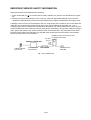
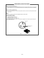
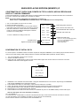
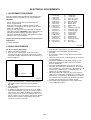
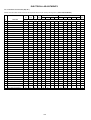
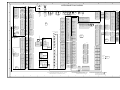
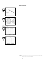
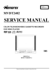
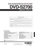
ELECTRICAL ADJUSTMENTS
1. ADJUSTMENT PROCEDURE
NO.
01
02
03
04
05
06
07
08
09
10
11
12
13
14
15
16
17
18
19
20
Read and perform these adjustments when repairing the
circuits or replacing electrical parts or PCB assemblies.
CAUTION
• Use an isolation transformer when performing any
service on this chassis.
• When removing a PCB or related component, after
unfastening or changing a wire, be sure to put the wire
back in its original position.
• When you exchange IC and Transistor with a heat sink,
apply silicon grease (YG6260M) on the contact section of
the heat sink. Before applying new silicon grease,
remove all the old silicon grease. (Old grease may cause
damage to the IC and Transistor).
Prepare the following measurement tools for electrical
adjustments.
1. Pattern Generator
NO.
22
24
25
26
27
28
29
30
31
35
36
37
38
39
40
63
64
65
66
67
FUNCTION
H POSI 60Hz
V POSI 60Hz
BAK LIGHT CENT
BAK LIGHT MAX
BAK LIGHT MIN
BRIGHT CENT
BRIGHT MAX
BRIGHT MIN
TINT
CONTRAST CENTER
CONTRAST MAX
CONTRAST MIN
COLOR CENT
COLOR MAX
COLOR MIN
CONTRAST 40
BRIGHT (3F54)
CONTRAST (3F55)
SRC TOP
DFEA VIMGVT
Fig. 2-2
2. BASIC ADJUSTMENTS
2-1: WHITE BALANCE
1. Place the set in Aging Test for more than 15 minutes.
2. Receive the gray scale pattern from the Pattern
Generator.
3. Press the INPUT button on the remote control to set to
the AV mode.
4. Using the remote control, set the brightness and contrast
to normal position.
5. Activate the adjustment mode display of Fig. 1-1 and
press the channel button (03) on the remote control to
select “R DRIVE (N)”.
6. Press the UP/DOWN button on the remote control to
select the “R CUTOFF (N)”, “B DRIVE (N)”, “B CUTOFF
(N)”, “R DRIVE (C)”, “R CUTOFF (C)”, “B DRIVE (C)”, “B
CUTOFF (C)”, “R DRIVE (W)”, “R CUTOFF (W)”, “B
DRIVE (W)” and “B CUTOFF (W)”.
7. Adjust the RIGHT/LEFT button on the remote control to
whiten the R CUTOFF (N), B DRIVE (N), B CUTOFF (N),
R DRIVE (C), R CUTOFF (C), B DRIVE (C), B CUTOFF
(C), R DRIVE (W), R CUTOFF (W), B DRIVE (W) and B
CUTOFF (W) at each step tone sections equally.
8. Perform the above adjustments 5 and 6 until the white
color is looked like a white.
On-Screen Display Adjustment
1. Set the VOLUME to minimum.
2. Press the VOL. DOWN button on the set and the
channel button (9) on the remote control for more than
2 seconds to display adjustment mode on the screen as
shown in Fig. 2-1.
TV
01 H POSI OSD
FUNCTION
H POSI OSD
V POSI OSD
R DRIVE (N)
R CUTOFF (N)
G DRIVE (N)
G CUTOFF (N)
B DRIVE (N)
B CUTOFF (N)
R DRIVE (C)
R CUTOFF (C)
G DRIVE (C)
G CUTOFF (C)
B DRIVE (C)
B CUTOFF (C)
R DRIVE (W)
R CUTOFF (W)
G DRIVE (W)
G CUTOFF (W)
B DRIVE (W)
B CUTOFF (W)
346
Fig. 2-1
3. Use the UP/DOWN button or Channel button (0-9) on
the remote control to select the options shown in
Fig. 2-2.
4. Press the MENU button on the remote control to end
the adjustments.
5. To display the adjustment screen for AV, YUV, HDMI
mode, press the INPUT button on the remote control to
set to the AV, YUV, HDMI. To display the adjustment
screen for DVD mode, press the TV/DVD button on the
remote control to set to the DVD. Press the VOL.DOWN
button on the set and the channel (9) on the remote
control for more than 2 seconds.
D-1