1
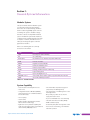
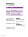
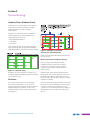
RADIANT HEATING SYSTEMS
UPONOR CLIMATE
˘ NTROl™ NETWORK
CO
s y s tem
USER MANUAL
A complete network approach for
controlling a home’s HVAC system
Uponor Climate Co˘ntrol™ Network
Operation Manual
Published by Uponor, Inc.
5925 148th Street West
Apple Valley, MN 55124 USA
Phone: (800) 321-4739
Fax: (952) 891-2008
Uponor, Ltd.
655 Park Street
Regina, SK S4N 5N1 CANADA
Phone: (888) 994-7726
Fax: (800) 638-9517
www.uponor-usa.com
www.uponor.ca
© 2008 Uponor
All Rights Reserved.
First Edition
First Printing, May 2008
Printed in the United States of America
2
www.uponor-usa.com • www.uponor.ca
Table of Contents
Section 1: General System Information
.
.
.
1
Modular System . . . . . . . . . . . . . . . . . . . . . . . . . . 1
System Capability . . . . . . . . . . . . . . . . . . . . . . . . . . 1
Communication and Networks . . . . . . . . . . . . . . . . . . . . . 2
System Setup . . . . . . . . . . . . . . . . . . . . . . . . . . . 2
Internet access . . . . . . . . . . . . . . . . . . . . . . . . . . . 2
Touch Panel Interface . . . . . . . . . . . . . . . . . . . . . . . . 2
Section 2: System Zoning . . . . . . . 3
Hydronic Zones (Radiant Zones) . . . . . . . . . . . . . . . . . . . . 3
Air Zones . . . . . . . . . . . . . . . . . . . . . . . . . . . . . 3
Master Thermostats and Master Passing
Section 3: System Functions . . . . . . . . . . 5
Radiant Floor Heating . . . . . . . . . . . . . . . . . . . . . . . . 5
Air Heating, Cooling and Circulation . . . . . . . . . . . . . . . . . . 5
Heat
Cooling
Manual
Supplementary Heating . . . . . . . . . . . . . . . . . . . . . . . 5
Ventilation and Air Quality Control . . . . . . . . . . . . . . . . . . . 5
First-stage Cooling
Humidity
Carbon Dioxide Control
Volatile Organic Compound Control
Manual Heat Recover Ventilator
Heat Recovery Ventilator (HRV) Air Handler Software Interlocks
Heat and Cool Staging . . . . . . . . . . . . . . . . . . . . . . . . 6
Cool Staging . . . . . . . . . . . . . . . . . . . . . . . . . . . 6
Heat Staging . . . . . . . . . . . . . . . . . . . . . . . . . . . 6
Section 4: Boiler Operation . . . . . . . . . . . 7
Flue Gas Condensation Prevention
Dual-stage Boiler
Multiple Boilers
Modulating Boilers
Supply Water Temperature Control . . . .
Domestic Hot Water (DHW) Control . . .
DHW Tank Control
Legionella Prevention
Boiler Purge
DHW Priority Controls
Snow Melting . . . . . . . . . . . .
Automatic Snow-melt Activation
Semi-automatic Snow-melt Activation
Generic Input and Output . . . . . . .
Uponor Climate Co˘ntrol™ Network System Manual
. . . . . . . . . . . . . . . 7
. . . . . . . . . . . . . . . 7
. . . . . . . . . . . . . . . 8
. . . . . . . . . . . . . . .
9
I
Section 5: System Modes . . . . . . . . . . .
11
Heat mode . . . . . . . . . . . . . . . . . . . . . . . . . . . .
Cool Mode . . . . . . . . . . . . . . . . . . . . . . . . . . . .
Auto Mode . . . . . . . . . . . . . . . . . . . . . . . . . . . .
Off Mode . . . . . . . . . . . . . . . . . . . . . . . . . . . . 11
11
11
11
Section 6: Schedules and Calendars . . . . . . . 13
Thermostat Schedules . . . . . . . . . . . . . . . . . . . . . . . Vacation Calendar . . . . . . . . . . . . . . . . . . . . . . . . .
Vacation Override . . . . . . . . . . . . . . . . . . . . . . . . .
Schedule-override Calendar . . . . . . . . . . . . . . . . . . . . . DHW Schedule . . . . . . . . . . . . . . . . . . . . . . . . . . 13
13
13
13
13
Section 7: Error Detection and Alarm Notification . 15
Section 8: Protection Limits . . . . . . . . . . 17
High-air Temperature . . . . . . . . . . . . . . . . . . . . . . . .
High-slab Temperatures . . . . . . . . . . . . . . . . . . . . . . .
Low Temperature . . . . . . . . . . . . . . . . . . . . . . . . . High Humidity . . . . . . . . . . . . . . . . . . . . . . . . . . Low Humidity . . . . . . . . . . . . . . . . . . . . . . . . . . .
Carbon Dioxide . . . . . . . . . . . . . . . . . . . . . . . . . .
Volatile Organic Compounds . . . . . . . . . . . . . . . . . . . . .
DHW Legionella Prevention . . . . . . . . . . . . . . . . . . . . . System Exercise . . . . . . . . . . . . . . . . . . . . . . . . . .
17
17
17
17
17
17
17
17
17
Appendix A: Connecting a DZCM or
Field Device Network . . . . . . . . . . . . . 19
Wiring . . . . . . . . . . . . . . . . . . . . . . . . . . . . . 19
Troubleshooting . . . . . . . . . . . . . . . . . . . . . . . . . . 20
Appendix B: Temperature
Sensor Troubleshooting . . . . . . . . . . . . 21
Temperature Resistance Chart for 10K J-curve Sensors . . . . . . . . . . . 21
Appendix C: Mix Channel Settings . . . . . . . . 23
Design Day Parameters . . . . . . . . . . . . . . . . . . . . . . . 23
Warm Weather Point . . . . . . . . . . . . . . . . . . . . . . . . 23
Mix Limits . . . . . . . . . . . . . . . . . . . . . . . . . . . . 24
Appendix D: Making a Cat5 Cable . . . . . . . . 25
II
www.uponor-usa.com • www.uponor.ca
Section 1:
General System Information
Modular System
The Uponor Climate Co˘ntrol™ Network System
is an innovative technology that integrates
and controls the complete heating, ventilation
and air-conditioning (HVAC) system of a home
or building. This system is modular in design
and can be scaled to fit any HVAC mechanical
system. The Network System allows installers to
configure and set up HVAC applications through
a computer or network, and it allows users to
make system changes through a convenient
graphical user interface.
Refer to the following table for commonly
used terms in this manual.
Term
Definition
%RH
Percentage of relative humidity
AC
Air conditioning
DeltaT (∆T)
Internal function to calculate temperature differential
DHW
Domestic hot water
DZCM
Digital Zone Control Module
FAC
Furnace Air Handler Control
HRV
Heat-recovery ventilator
HVAC
Heating, ventilation and air conditioning
LED
Light-emitting diode
UCT
Uponor Configuration Tool
VOC/CO2 sensors
Sensors that detect volatile organic compounds and carbon dioxide
ZVDC
Zone Valve and Damper Control
Table 1-1: Common Terms
System Capability
• 99 thermostat-controlled hydronic zones
• 16 air zones
• 12 Digital Zone Control Modules (DZCMs)
each supporting up to 10 manifold actuators
and 10 thermostats
• 16 zone pumps
• Five mixed-water temperatures (injection
pumps and/or modulating valves)
• Five single-stage or modulating boilers or two
dual-stage boilers
• One primary loop with one set of boiler
supply-and-return sensors
• 16 zone valves
• Up to four individual zones of snow melting
• Eight air handlers (including fans, furnace
burners and air conditioning)
• Two tanks of domestic hot water (DHW)
• DHW recirculation pump
• Eight heat-recovery ventilators (HRVs) and
eight optional volatile organic compounds and
carbon dioxide (VOC/CO2) sensors
• Geothermal pump with reversing valve control
Uponor Climate Co˘ntrol™ Network System Manual
• Four zones of snow melting, semi-manual or
automatic operation
1
Communication and Networks
The system works by passing data through a series of
communication networks. A fully implemented system
uses four networks: thermostat, zone control, field
device and ethernet, described in Table 1-2.
Network
Thermostat Network
Description
The thermostats on a DZCM run on a network to transfer readings and setpoints between the thermostats and the rest of the control system.
Zone Control Network The DZCMs communicate with each other and transfer data to the
main controls to operate various outputs when thermostats call for
heating, cooling or ventilation.
Field Device Network
This network handles control signals to and from the field devices including the HRV controls, the zone valve and damper controls
(ZVDCs) and the air handler controls (FACs).
Ethernet Network
The ethernet network connects the Uponor Climate Co˘ntrol™
Network System to the Uponor network via the internet.
This network allows a user to access the system and make
any setpoint changes or setup changes to the control system
from anywhere a Web browser is available.
Table 1-2: Network Descriptions
The network system has a modular organization,
with smaller system functions controlled through
specific hardware within the network structure. This
configuration makes targeting and controlling specific
system functions easier than conventional systems that
send raw signals through many individual wires to a
central control location.
System Setup
In a conventional control system, wiring configures the
system. Accordingly, the way an installer physically wires
the controls together defines how the system will control
the equipment.
The Network System is mostly software configured,
so most installations feature similar wiring connection
patterns. Equipment functionality is set up in the control
system through the Uponor Configuration Tool (UCT).
Internet Access
Accessing the system is easy because the Climate
Co˘ntrol Network System talks to the Uponor North
American server through the internet. Once a user
establishes a link, the homeowner or contractor can log
in to Uponor’s exclusive website at www.myuponor.net
using a secure user name and password. For your secure
user name and password, contact the Uponor Climate
Co˘ntrol Network System Administrator at
(952) 997-5333.
Touch Panel Interface
If you prefer not to connect your system to the internet,
you can purchase a Touch Panel Interface (A9070000)
from Uponor to provide a single point of access to
view and set all information within the system (e.g.,
thermostats, DHW, snow melt, schedules, etc.).
The UCT is an intuitive software program for configuring
the Network System. At setup, you enter the system
information and save it in real time to a file.
2
www.uponor-usa.com • www.uponor.ca
Section 2:
System Zoning
Hydronic Zones (Radiant Zones)
A hydronic zone is an area for which a set of hydronic
devices delivers heat. Each thermostat is assigned
a different hydronic zone and zone number
within a system.
A hydronic zone can include various combinations of
hydronic equipment. For example, Hydronic Zone
10 (Living Room) can consist of:
• Water Temperature Channel 2
• Zone Valve 4
• Zone Pump 6
In this example, whenever a thermostat controlling the
living room calls for heat, the system will start Water
Temperature Channel 2, Zone Valve 4 and Zone Pump 6.
Figure 2-4: Example of a Possible
Zone Layout – Air and Hydronic
An Uponor Climate Co˘ntrol Network System can support
up to 16 air zones.
Master Thermostats and Master Passing
Figure 2-1: Hydronic Zones
An air zone may contain multiple thermostats.
A multiple-thermostat system must use a master
thermostat to control the air-system equipment
common to all thermostats in that air zone (or airdelivery system).
Air Zones
A feature called "master passing" determines which
thermostat has control of the equipment in an air zone.
All Climate Co˘ntrol Network thermostats may become
the master of their air zones unless they are set as Never
the Master via the UCT.
Air zones are areas for which a set of air-handling
devices delivers either warm or cool air. Air zones
generally contain multiple hydronic zones and, therefore,
multiple thermostats. For example, Air Zone 2 can
include Air Handler 3, Heat-recovery Ventilator 4 and
Zone Damper 7.
An Uponor Climate Co˘ntrol Network thermostat becomes
the master of its air zone whenever it is used to change
a setting. For example, if you change the cooling
setpoint in a room, the thermostat you use to change it
automatically becomes the master thermostat of that
air zone.
A hydronic zone can be assigned to a single air zone.
The Uponor Climate Co˘ntrol Network System can include
up to 99 hydronic zones.
Uponor Climate Co˘ntrol™ Network System Manual
3
When a thermostat becomes the master thermostat, an
icon appears on the thermostat’s screen (see Figure
2-3). This icon signals the user that the thermostat is
now the master thermostat.
Figure 2-3: Master Thermostat Icon
The other, non-master thermostats in an air zone
will display AU (automatically controlled) when the
user attempts to change a setpoint. If you want that
thermostat to take over as the master, press the (+) or
(–) button again and that thermostat will become the
master for that air zone.
4
www.uponor-usa.com • www.uponor.ca
Section 3:
System Functions
The Uponor Climate Co˘ntrol Network System can direct
operations of the HVAC systems in a home or building.
Radiant Floor Heating
Radiant floor heating may be controlled through and
associated with any combination of:
• A single zone valve
• Zone pump
• Mixed water temperature channel
• Actuator-controlled manifold valve
You can set up associations among thermostats, zones
and radiant floor heating in the UCT.
Air Heating, Cooling and Circulation
The Uponor Climate Co˘ntrol Network System can control
air handlers with fans, air-conditioning compressors,
cooling coils and furnace burners. You may also damper
up to 16 air zones. Associations among thermostats,
zones and the air-handling equipment are made in the
Thermostat Setup menu of the UCT.
Heat
Forced-air heat control is available in the Network
System and can be used as a supplement to radiant floor
heating. Install the forced-air heat function via a furnace
or a hydronic heating coil in the air plenum.
Cooling
Forced-air cooling is the main source of cooling in the
Network System. The ventilation system (if available)
begins as a first stage, but the system performs most
cooling with a refrigerant compressor (or chiller),
duct-mounted cooling coil and fan. The software
implements a restart timeout and adjustable outdoor
temperature lockout to protect refrigerant compressors
from mechanical failure.
Manual
You can set the air handler fan in an air zone to a
Manual On mode for air circulation. The Manual On
mode runs the fan continuously or for a preset amount
of time as defined in the UCT.
You can access manual fan control through a
thermostat. Refer to the Uponor Climate Co˘ntrol
Network System Thermostat Installation and Operation
Manual for instructions to set the manual fan setpoint.
Uponor Climate Co˘ntrol™ Network System Manual
Supplementary Heating
The Uponor Climate Co˘ntrol Network System also
manages a third source for heat delivery. Examples of
this supplementary heat include hydronic kick-space
heaters and hydronic baseboard or radiators.
It is possible to use supplementary heat control for
permanent electrical heating devices. Network System
outputs will need to control appropriate line-voltage
relays and contacts as designed and supplied by a thirdparty vendor. To set up electrical heating devices, use
the UCT to configure associations among thermostats,
zones and the supplementary heating equipment. The
flexibility of the Climate Co˘ntrol Network System allows
multiple stages of heat to run at the same time (e.g.,
radiant and supplemental).
Ventilation and Air Quality Control
The Network System may also include HRVs and
optional VOC/CO2 sensors. All air quality control
settings, zoning and interlock settings for ventilators,
humidity equipment, sensors, etc. are available
in the UCT.
First-stage Cooling
The Uponor Climate Co˘ntrol Network System uses
the ventilation system as the first cooling stage if it is
available. This approach provides an economical cooling
solution (compared with forced-air cooling) on days with
very low cooling loads or when outdoor temperatures are
too low to operate conventional cooling equipment.
Humidity
Humidification and dehumidification are also available in
the Network System. Every Network System thermostat
includes a relative humidity (RH) sensor. The RH
readings of all of the thermostats in an air zone are
averaged to produce a control reading.
The RH setpoint can only be set within a certain
range based on the outdoor temperature measured by
the system. This limit prevents condensation on the
windows and in the walls during cold weather. As the
outdoor temperature moves, the RH setpoint range will
adjust automatically.
When an air zone calls for dehumidification, the
ventilation system runs in a preset mode to reduce the
5
humidity. If a dehumidifier is set up in the air zone, the
dehumidifier and its associated fan will turn on. When
the system calls for humidification, the humidifier and its
associated fan will initiate.
Carbon Dioxide Control
Carbon dioxide is a naturally occurring gas that is
colorless, odorless, incombustible and formed during
combustion and respiration. Therefore, carbon dioxide is
a good indicator of stale or dirty air. It is unhealthy and
uncomfortable to be surrounded by too much carbon
dioxide. For this reason, the Uponor Climate Co˘ntrol
Network System can be equipped with an optional
VOC/CO2 sensor package. With this sensor and a
ventilation system, the Network System will activate the
ventilator to ensure the lowest possible level of carbon
dioxide in the home or building.
HRVs are often installed with ducting that is shared
with air handling units. In this case, the HRVs require
the air handler fans to operate with the HRV. The
Network System has the ability to interlock the HRV
with its associated air handler via the UCT. This feature
avoids unnecessary wiring between the HRV and the
air handler. The installer can use the UCT to set up the
interlocks.
Heat and Cool Staging
All staging in the Network System is based on
differentials (i.e., the difference between reading and
applicable setpoint). The differential settings are fixed
and are not a configured setting.
Volatile Organic Compound Control
Cool Staging
Volatile organic compounds are unwanted carbon
compounds that have evaporated into the air. These
compounds are often released into the air by such things
as new furniture, new carpet, new paint, new caulking,
etc. With the VOC/CO2 sensor and a ventilation system,
the Network System activates the ventilator to ensure
the lowest possible level of volatile organic compounds
in the home or building.
There are three conditions that control how cool staging
is handled for an air zone.
Manual Heat-recovery Ventilator
•If a ventilation system is available, it will automatically
activate for first-stage cooling.
•If the ventilation system alone cannot handle the
entire cooling load and the differential between
setpoint and reading grows to a preset value, the
Network System will activate the air conditioner and
fan as well.
An HRV is a device that brings fresh air inside the home
or building while recovering a portion of the heat from
the stale air before it is exhausted. In certain areas,
HRVs are mandated by code; in other areas, they are
optional.
•If a ventilation system is not installed, then air
conditioning automatically is the first and only
cooling stage.
You can set the HRV in an air zone to run manually. In
the case of a multi-speed HRV, the Manual On mode
will activate the HRV to run at high or medium speed for
the period of time you have defined in the configuration
software. If the HRV is set to Manual Low, it will run on
low speed indefinitely until the user changes the HRV to
Manual Off.
The UCT allows any of the three available sources of
heating to be configured for first stage and second
stage in any combination.
In the case of a single-speed HRV, the Manual High
mode will activate the HRV for the preset amount of
time (i.e., time selected at setup). If the HRV is set to
Manual Low mode, it runs for 20 minutes and then turns
off for 40 minutes. The HRV will operate in this mode
indefinitely until the user sets the HRV to Manual Off.
Any other HRV call from the system including %RH calls,
volatile organic compound/carbon dioxide calls and vent
cooling will override the manual setting. You can access
manual HRV control through a thermostat. Refer to the
Uponor Climate Co˘ntrol Network System Thermostat
Installation and Operation Manual for instructions to set
the HRV manual setpoint.
6
Heat-recovery Ventilator and Air Handler
Software Interlocks
Heat Staging
The three sources of staged heating are as follows:
• Radiant floor heating — Warm water circulating
through the floor or other panel
• Forced-air heat — Heat from a furnace or hydronic
heating coil in the air plenum
• Supplemental heat — Baseboard heaters, radiant
ceiling, kick-space heaters, etc.
These three heat sources are turned on and off by preset
differentials, based on how the system is configured.
The first stage runs on a smaller differential than the
second stage. If the first-stage heat source cannot meet
the heating load alone and the differential between
setpoint and reading continues to grow, the second
stage will activate.
www.uponor-usa.com • www.uponor.ca
Section 4:
Boiler Operation
The Network System starts and maintains the boiler after
establishing the required demand from the thermostats,
mix channels, snow melt and DHW.
Supply Water Temperature Control
The boiler target temperature is calculated continuously
from the hottest water demand on the system. Refer to
the boiler manufacturer’s literature for information about
the minimum and maximum water temperature settings.
Flue Gas Condensation Prevention
By controlling the output of the mixed water channels,
the Network System will control the return water
temperature to the boiler. This feature prevents flue
gasses from condensing in the boiler and causing
damage. The minimum boiler water temperature variable
sets the limit for flue gas condensation prevention.
When condensing boilers are installed, the minimum
boiler return temperature can be disabled.
Dual-stage Boilers
The Uponor Climate Co˘ntrol Network System will
automatically control both stages of a dual-stage boiler
to provide the most efficient operation possible. To
facilitate control of two-stage boilers, set the boilerstaging aquastats on the boiler higher than the system’s
control range (e.g., 210°F or 98°C).
Multiple Boilers
The Network System can control up to five single-stage
boilers or up to two dual-stage boilers, optimizing the
run time of all boilers in a multiple-boiler system. If the
system is controlling multiple dual-stage boilers, the
second boiler will not fire unless both stages of the first
boiler cannot meet the heating demand.
Modulating Boilers
The Climate Co˘ntrol Network System controls
modulating boilers one of two ways.
•A modulating boiler that performs its own modulation
control may run as a standard boiler via a Climate
Co˘ntrol Network System Boiler Relay (A9012010).
In this case, the Network System will simply send a
demand call to the boiler to begin heating, and the
boiler will manage its own fire level.
•If a 0-10VDC control input is available on the boiler
(for example, EC10, AM4, etc.), the Network System
can control the boiler’s fire level with the use of a
0-10VDC Modulating Boiler Control (A9012020).
Uponor Climate Co˘ntrol™ Network System Manual
Figure 4-1: Supply Water Temperature Control
The Supply Water Temperature Control (A9013000)
regulates the mix rate using a modified outdoor reset
algorithm, factoring in the offset from the thermostat
demands. Refer to Appendix C on page 23 for details
about the mix channel settings.
Five mixed water temperature channels are available
for use. These mixed water channels can mix water
for radiant floor heating, supplemental heating, snow
melting or any other hydronic application where
mixing/reset is required. The water temperatures are
reset based on outdoor temperature, so the system
satisfies the heating load without overheating the
radiant panel or terminal device.
The settings that determine the characteristic of the
heating reset curve are defined at installation via the
UCT. The Network System supports injection mixing
pumps, three-way modulating valves or a combination
of both.
Domestic Hot Water Control
DHW Tank Control
The Network System can control up to two indirect-fired
DHW tanks separately. The control requires placing a
sensor in the sensor well of the tank. A setpoint then
keeps the tank at a user-selectable temperature.
7
The user can define the tank setpoint with the UCT, the
system website or the Uponor Touch Panel Interface.
If controlling two tanks, you can schedule them
individually. During DHW scheduled on times, the
system will keep the tank within 9°F (5°C) of the
user-defined setpoint. In scheduled off periods, the
tank is not controlled and will eventually fall to room
temperature.
Snow Melting
DHW Recirculation
The Network System supports DHW recirculation
if there is only one DHW tank in use. When the
DHW schedule is on, the recirculation pump runs
continuously. When the schedule is off, it will run to
keep a 109ºF (43ºC) minimum temperature in the hot
water pipes to prevent Legionella bacteria from growing.
When the system is in Vacation mode, the DHW
recirculation turns off completely.
Legionella Prevention
If the DHW tank or tanks fall below 109ºF (43ºC) for
a period of five days (e.g., the system is in Vacation
mode), the tank will reheat to 140ºF (60ºC) to prevent
Legionella bacteria from growing.
Boiler Purge
When enabled, this feature dumps excess hot water into
the DHW tank at the end of a call for heat if the tank
temperature is below its setpoint.
DHW Priority Controls
On a DHW call, the Network System determines whether
the boiler output can satisfy the DHW and the heating
load. If the boiler cannot satisfy both DHW and heating
loads, the mix channel’s output is reduced to allow the
DHW tank to reheat. Likewise, zone pumps are shut
down in sequence as the boiler temperature reaches its
lower limit.
Figure 4-2: Snow Melt Control
Snow-melting functionality is available within the
Uponor Climate Co˘ntrol Network System. The snow-melt
system only operates when the outdoor temperature is
within a preset range defined in the UCT at setup.
Each snow-melt zone can be assigned to one of the
five available water temperature channels in the Supply
Water Temperature Control (A9013000) to mix water for
the snow-melt slab.
The control system will limit the differential between
the temperatures of the water going to and coming
back from the slab to a safe amount, thereby
protecting the slab.
If a heating device capable of controlling the water
temperatures is installed for the snow-melt system, then
you will not need to assign a water temperature channel.
The snow-melt system will be disabled if the outdoor
temperature in the slab is too warm to trigger
the heating device, yet the ambient outdoor (air)
temperature may be too cold to completely melt and
dry the area. Refer to Appendix C for more information
about how these temperature parameters are configured
for snow-melt control devices.
Automatic Snow-melt Activation
If using an Uponor Climate Co˘ntrol Network Automatic
Snow and Ice Sensor (A9013052), the snow-melt
activation will start when the sensor detects snow or
ice. The system will continue to apply heat to the snowmelting slab for the minimum time specified at setup
(the default time is 4 hours).
Note: The snow and ice detector has a minimum run
time of one hour.
8
www.uponor-usa.com • www.uponor.ca
Semi-automatic Snow-melt Activation
Manually start a snow-melt system by pressing a
momentary switch. Mount a remote switch indoors for
this purpose or use the manual switch on the Snow Melt
Control (A9013051).
Hold the switch for at least five seconds to guarantee
activation. The snow-melt system will run for a set
period of time once it is manually activated. You can
adjust this time via the UCT. The Network System will
ramp up the temperature of the slab and hold it at the
preset idle temperature until the time limit expires.
General Input and Output
Figure 4-3: General Input and Output Module
The General Input and Output Control (A9011600) lets
the Network System transmit alarms that are based
on up to eight inputs. It can also activate up to eight
outputs based on schedules.
Outputs can be used for other systems, such as lawn
sprinklers or yard-accent lighting — essentially anything
that runs on a schedule.
Inputs can be connected to devices providing a
dry-contact signal, such as an alarm indicator
(e.g., basement moisture detection, carbon monoxide
detection, etc.).
Important: Do not use for the General Input and
Output Module for life-safety systems or security
systems. Uponor takes no responsibility for
damages or loss occurring because an alarm was
not sent or not sent promptly.
Uponor Climate Co˘ntrol™ Network System Manual
9
10
www.uponor-usa.com • www.uponor.ca
Section 5:
System Modes
An air zone can be set to the following four modes:
Heat, Cool, Auto and Off.
Heat Mode
If an air zone is in Heat mode, it will only supply heat
to the space. In Heat mode, the system is driven by
thermostat heat setpoints only.
Cool Mode
If an air zone is in Cool mode, it will supply cooling
to the space. However, the system may apply heat
to radiant floors for floor warming while the system
is cooling the air. The system requires a slab sensor
connected to a thermostat for this option.
In Cool mode, the system reads the cooling setpoints
on the master thermostats and the slab setpoints for all
radiant floor thermostats with slab sensors.
Auto Mode
If an air zone is in Auto mode, it automatically switches
back and forth between heat mode and cool mode
depending on the need for heating or cooling. Auto
mode uses either the cooling or heating setpoint of the
master thermostat to run the heating or cooling mode,
as required.
While changing a temperature setpoint via a thermostat,
either the heating or cooling mode icons will flash to
signify which setpoint you are adjusting.
Off Mode
When an air zone is in Off mode, it will not supply
heating, cooling or floor warming. Protection limits
remain enabled to force heating or cooling if necessary.
Uponor Climate Co˘ntrol™ Network System Manual
11
12
www.uponor-usa.com • www.uponor.ca
Section 6:
Schedules and Calendars
Multiple scheduling and calendar functions are built into
the Uponor Climate Co˘ntrol Network System.
All schedules and calendars are adjustable from
the UCT or the Touch Panel Interface.
Thermostat Schedules
There are 16 thermostat schedules available. Each
schedule may be configured differently, and each
thermostat may be configured to follow any of the
16 schedules.
The system only follows thermostat schedules if the
thermostat enables them and the system is in
Auto mode.
During a schedule’s off period, the thermostat will follow
the vacation setpoints. During thermostat setup, you can
turn Schedule Enable on or off. If Schedule Enable is off,
the thermostat will not follow any schedule.
Vacation Calendar
The Vacation Calendar allows the system to run from
its vacation setpoints during an extended absence. All
vacation setpoints are accessible from the UCT locally or
via the Touch Panel Interface.
DHW is also shut down over vacation periods. If
Legionella prevention is enabled, the tank will
periodically reheat to prevent Legionella bacteria from
growing.
Vacation Override
If the system is in Vacation mode and a user adjusts a
thermostat, the system begins Vacation-override mode
for four hours. Once the four-hour timer expires, the
system will return to Vacation mode and follow vacation
mode setpoints.
Schedule-override Calendar
The Schedule-override calendar allows a user to override
the regular schedules for entire days. For example, you
may want to set the Schedule-override calendar for
holidays when you will be at home and want the system
to run instead of shutting down for a scheduled off
period.
DHW Schedule
See the DHW Control section on pages 7-8.
Uponor Climate Co˘ntrol™ Network System Manual
13
14
www.uponor-usa.com • www.uponor.ca
Section 7:
Error Detection and Alarm Notification
The Network System can detect and notify you about
various problems occurring in your heating, cooling
and ventilation system. When an alarm activates in
the system, it sends an e-mail to the Uponor North
American server. The e-mails are then automatically
sorted and relayed to a user-defined e-mail list.
To change the e-mail list for your installation,
contact the Uponor Climate Co˘ntrol Network System
Administrator at (952) 997-5333.
The following alarms initiate an e-mail:
• High-temperature limit reached on any
of the thermostats
• Low-temperature limit reached on any
of the thermostats
• Low system pressure, which equires a Network
System Pressure Switch (A9012004)
• Primary pump disconnected
• DHW pump disconnected
• DHW recirculation pump disconnected
• Mix pump disconnected
• Secondary pump disconnected
• Zone pump disconnected
• General input and output event
Uponor Climate Co˘ntrol™ Network System Manual
15
16
www.uponor-usa.com • www.uponor.ca
Section 8:
Protection Limits
Many protection-level functions are built into the
Uponor Climate Co˘ntrol Network System to keep you
and your home as safe and comfortable as possible.
In any mode, conditions throughout the Network
System are monitored to protect the residence.
In normal operation, these protection limits
should never be reached.
High-air Temperature
If any air temperature sensor indicates a temperature
above 95°F (35°C), the thermostat will initiate an
air-cooling call in all air zones until the temperature
decreases. The air-cooling call will bring on firstand/or second-stage cooling if the equipment
exists and is in temperature range.
High-slab Temperatures
Slab-sensor readings that are greater than the maximum
slab setpoint will stop a heat demand.
Low Temperature
The system will initiate a system-wide heat demand
if any air temperature sensor indicates a temperature
below 35°F (2°C).
High Humidity
If humidity rises above 80% in any air zone, the
system will attempt to reduce the relative humidity level
to 75%.
Volatile Organic Compounds
If volatile organic compound levels reach the
maximum setting (non-adjustable), the system
will activate the HRV at high speed until the system
detects normal levels.
DHW Legionella Prevention
When the DHW tank sensor is set and the user has
enabled the Legionella prevention option, two situations
will activate this option.
1. When the system is put into vacation mode, the
system ignores the setpoint for the tank and water
in the tank cools. If the temperature remains below
109°F (43°C) for five days, the tank will reheat
to 140ºF (60ºC) to prevent Legionella bacteria
from growing.
2. If someone manually adjusts the setpoint
temperature for the tank and water in the tank
remains below 140ºF (60ºC) for five days, the tank
will reheat to 140ºF (60ºC) to prevent Legionella
bacteria from growing.
System Exercise
If any part of the heating delivery system is inactive for
seven days, system pumps, valves and actuators will
activate for up to 10 minutes.
Low Humidity
If any humidity sensor reading falls below 20%, the
system will deactivate the HRV for the air zone unless
the HRV is in Manual mode. The low-limit flag resets
once the humidity level rises above 25%. If the system is
configured to control a humidifier, the system will work
to increase the humidity level whenever possible.
Carbon Dioxide
If carbon dioxide levels reach 1,500 PPM, the system
will activate the HRV on high speed until the level is
decreased to 1,200 PPM.
Uponor Climate Co˘ntrol™ Network System Manual
17
18
www.uponor-usa.com • www.uponor.ca
Appendix A:
Connecting a DZCM or Field Device Network
Wiring
When wiring these networks, refer to the following rules.
DZCM and field device networks are generally wired with
Cat5 wire. These networks can be wired and arranged in
a wide variety of configurations. You can use a Network
System Y-Connector (A9011003) at any point in the
Uponor Climate Co˘ntrol Network System to create
another network leg, which can be very useful in homes
with wings or many floors.
1. Do not leave any Cat5 plug or receptacle in the
Network System unconnected except on the router.
Leaving any part of the network unconnected will
result in unpredictable network operation.
2. Fill network plugs on the router from the top down.
3. If using network wire converters, make sure that the
18 AWG wire connected to them does not exceed
200 feet.
Use network wire converters to convert the Cat5
connections to 18-2 LVT terminal blocks for
retrofit installations.
4. Ensure that the plugs on Y-Connectors are all
identical (i.e., there are no specific in or out plugs).
See Figure A-1 for examples of network wiring.
Figure A-1: Network Wiring Examples
Uponor Climate Co˘ntrol™ Network System Manual
19
Troubleshooting
TX and RX light-emitting diodes (LEDs) locations:
• On the DZCM, the LEDs are located immediately
above the map button.
• On the field devices, the LEDs are located just above
and to the left of the manual switch.
Monitor both the TX and RX LEDs to assess the
operational status of the network communications.
See Table A-1 for LED definitions.
Red
TX LED
GreenStatus
TX LED
Remedy
Flashing
Flashing
Normal communication
None required
Flashing
Not lit
Network wiring problem
Test or rewire Cat5 cabling
Not Lit
Flashing
Network wiring problem
Test or rewire Cat5 cabling
Solid
Not Lit
Power wiring problem
Change 24VAC input polarity
Not Lit
Solid
Power wiring problem
Change 24VAC input polarity
Table A-1: LED Definitions
20
www.uponor-usa.com • www.uponor.ca
Appendix B:
Temperature Sensor Troubleshooting
Temperature Resistance
All the temperature sensors in the Uponor Climate
Co˘ntrol Network System are 10K J-curve sensors.
If a sensor is reporting a value that does not seem
accurate, test the sensor with the data in Table B-1.
Note that the sensors maintain a tolerance
of +/– 0.54°F (+/– 0.3°C).
Temperature
R
Temperature
R
Temperature
R
ºC
Ω
ºC
Ω
ºC
ºF
Ω
ºF
ºF
-45.0 -49.0
471985.0
9.0
48.2
20882.0
63.0
145.4
2235.0
-42.0 -43.6
384703.0 12.0
53.6
18090.0
66.0
150.8
2011.0
-39.0 -38.2
314904.0 15.0
59.0
15712.0
69.0
156.2
1813.0
-36.0 -32.8
258838.0 18.0
64.4
13681.0
72.0
161.6
1637.0
-33.0 -27.4
213610.0 21.0
69.8
11942.0
75.0
167.0
1480.0
-30.0 -22.0
176974.0 24.0
75.2
10450.0
78.0
172.4
1340.0
-27.0 -16.6
147177.0 27.0
80.6
9165.0
81.0
177.8
1215.0
-24.0 -11.2
122847.0 30.0
86.0
8057.0
84.0
183.2
1104.0
-21.0
-5.8
102906.0 33.0
91.4
7098.0
87.0
188.6
1005.0
-18.0
-0.4
86501.0 36.0
96.8
6267.0
90.0
194.0
915.5
-15.0
5.0
72957.0 39.0
102.2
5545.0
93.0
199.4
835.4
-12.0
10.4
61736.0 42.0
107.6
4917.0
96.0
204.8
763.5
-9.0
15.8
52407.0 45.0
113.0
4368.0
99.0
210.2
698.7
-6.0
21.2
44626.0 48.0
118.4
3888.0
102.0
215.6
640.3
-3.0
26.6
38115.0 51.0
123.8
3468.0
105.0
221.0
587.6
0.0
32.0
32650.0 54.0
129.2
3099.0
108.0
226.4
539.9
3.0
37.4
28052.0 57.0
134.6
2774.0
111.0
231.8
496.7
6.0
42.8
24170.0 60.0
140.0
2488.0
114.0
237.2
457.5
Table B-1: Temperature Resistance Chart for 10K J-Curve Sensors
Uponor Climate Co˘ntrol™ Network System Manual
21
22
www.uponor-usa.com • www.uponor.ca
Appendix C:
Mix Channel Settings
The Uponor Climate Co˘ntrol Network System supports
up to five mix channels per installation. Each mix
channel uses a supply-and-return sensor to control the
average temperature in the output device. The Network
System uses an internal function, DeltaT (∆T), for
calculating temperature differentials between the supply
and return legs of an output device.
The system uses eight variables to specify the mix
channel output requirements —four to describe designday parameters, two to describe the warm weather
parameters and two for setting mix limits.
These mix channel output requirements are classified
as follows:
Warm Weather Point
The warm weather point fixes the supply curve at a
warm temperature (see Figure C-1 to view a graph of
the mixed water temperature curve). The warm weather
point tells the control what temperature to provide
when the heat load is small. Two data fields describe
this point.
Data Field
Definition
Warm weather mix temperature
This is the average required
temperature the channel should be
when the outdoor temperature is
warm.
This is the temperature
value used to control the warm
weather mix temperature.
• Design-day parameters — describe the mix operation
under full heating load (design conditions)
Warm weather
outdoor
temperature
• Warm weather parameters — describe the mix
operation when the heating load is the lowest
Table C-2: Warm Weather Data Fields
• Mix limits — describe the mix operations at outdoor
temperatures less than design day and greater than
the warm weather point
Following are examples of warm weather mix
temperature (WMT) settings:
See Figure C-1 for an example of a mixed water
temperature curve.
Design-day Parameters
The design-day parameters specify the mix-channel
output when the outdoor temperature is the coldest
as specified by the American Society of Heating,
Refrigerating and Air-conditioning Engineers (ASHRAE)
for the installation.
Type
Required Required WMT
Temperature Delta TSetting
Radiant Floor
70°F
10°F
75°F
Baseboard
130°F
20°F
140°F
Fan Coil
140°F
20°F
150°F
Table C-3: Warm Weather Point Temperatures
The Uponor Climate Co˘ntrol Network System requires
the following four data fields to describe design day.
Data Field
Definition
Design mix temperature This is the supply water temperature that the installation requires when the outdoor
temperature reaches the coldest that can be expected. This value is produced from the
radiant design program (Uponor System Design Software or Advanced Design Suite™).
Design Delta temperature
This is the designed difference between the supply and return leg of the output as required
by the hydronic device (e.g., radiant floor heating panel, baseboard, fan coil, etc.).
Design outdoor temperature This is the temperature value used to control the design mix temperature.
Design indoor temperature
This is the indoor temperature that is required when the outdoor temperature is
at the same value as the design outdoor temperature.
Table C-1: Design Day Data Fields
Uponor Climate Co˘ntrol™ Network System Manual
23
Mix Limits
Each mix channel has upper and lower limits to prevent
the mix output, as read by the mix channel supply
sensor, from reaching above or below a certain value.
• Minimum temperature (MinT) is the minimum
allowable temperature the mix channel can produce.
MinT limits the mix temperature when the outdoor
temperature rises above the warm weather outdoor
temperature.
• Maximum temperature (MaxT) is the maximum
allowable temperature the mix channel can produce.
MaxT limits the mix temperature when the outdoor
temperature falls below the design outdoor
temperature. See Table C-4 for various setting
examples.
Installation
MinT MaxT TypeSettingSetting
Quik Trak® - Floor
70°F
180°F
Quik Trak® - Ceiling / Wall
70°F
120°F
Radiant Floor Heating — Concrete
70°F
150°F
Radiant Floor Heating —
Joist
70°F
180°F
Kick-space Heater
110°F
190°F
Fan Coil
140°F
200°F
Baseboard
140°F
200°F
Note: To force the mix channel to
produce only one temperature
on a demand, simply set
MinT and MaxT to the same
desired value. Setting MinT
and MaxT to the same value
will override the other mix
settings.
Mixed Water Temperature
Table C-4: MinT and MaxT Setting Examples
Max Supply Water
Temperature (MaxT)
Average Water
Temperature at
Design Day
[DMT-(DDT/2)]
Warm Weather Mix
Temperature (WMT)
Minimum Supply Water
Temperature (MinT)
Design Outdoor
Temperature (DOT)
Warm Weather Outdoor
Temperature (WOT)
Outdoor Temperature
Figure C-1: Mixed Water Temperature Curve
24
www.uponor-usa.com • www.uponor.ca
Appendix D:
Making a Cat5 Cable
Refer to the following instructions to make a Cat5 cable.
Note: There are two protocols for making Cat5
(or ethernet) cables — T568A and T568B.
The Uponor Climate Co˘ntrol Network System
uses T568B.
2. Using either the attachment on the RJ45 crimp tool,
a knife or wire strippers, strip approximately ½-inch
of outer insulation from the wire cable (see
Figure D-2).
Tools required:
• Wire cutters
• Cable stripper (optional)
• RJ45 crimp tool
• RJ45 connectors
• Cat5 cable
• Cable tester
Procedure
1. Using wire cutters, cut the end of the wire. Ensure
the individual wires inside are even (see Figure D-1)
Figure D-2: Stripping the Outer Insulation
Note: Take care not to damage the inner insulation or
wires. If damage occurs, cut off the damaged end
and start over at step 1.
3. Separate all eight wires and straighten them (see
Figure D-3)
Figure D-1: Cutting the Cable Wiring
Figure D-3: Separating the Wires
Uponor Climate Co˘ntrol™ Network System Manual
25
4. Arrange the wires from left to right in the following
order (see Figures D-4 and D-5).
6. Trim the tips of the wires so they are even (see
Figure D-7). Make sure there is about ½-inch of
wire to insert into the connector.
Pin Number
Color
Figure D-4: Wire Arrangement
Figure D-7: Trimming the Wires
7. Holding the wires with the white/orange on the
left and the brown on the right, slide on the RJ45
connector. Ensure the metal pins are facing up and
the locking tab is facing down (see Figure D-8).
Figure D-5: Straightening the Wires
5. Push the wires together in a neat row. It may help to
hold the wires between the index finger and thumb
of one hand while straightening them with the other
hand (see Figure D-6).
Figure D-8: Sliding on the RJ45 Connector
Figure D-6: Preparing to cut the Wires
26
www.uponor-usa.com • www.uponor.ca
8. Make sure all wires reach the end of the RJ45
connector. Rotate the plug for visual inspection (see
Figure D-9).
Figure D-9: The Wiring Assembly
11.Test the cable before installation (see Figure D-11).
Refer to the cable tester manufacturer’s literature
for proper cable testing instructions.
Figure D-11: Testing the Cable
9. Insert the assembly into the crimper and tightly
crimp the connector (see Figure D-10).
Figure D-10: Crimping the Wire Assembly
10.Repeat steps 1 through 9 for the other end of the wire, using the same color order as the first end.
Uponor Climate Co˘ntrol™ Network System Manual
27
CCN_SysMan_H079_5-08, Copyright © 2008 Uponor, Printed in the United States
Uponor, Inc.
5925 148th Street West
Apple Valley, MN 55124 USA
Tel: (800) 321-4739
Fax: (952) 891-2008
Web: www.uponor-usa.com
Uponor Ltd.
655 Park Street
Regina, SK S4N 5N1 CANADA Tel: (888) 994-7726
Fax: (800) 638-9517
Web: www.uponor.ca