1
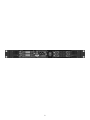
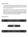
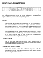
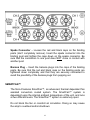
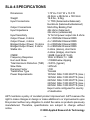
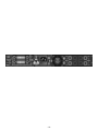
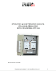
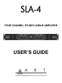
SLA-4
FOUR CHANNEL STUDIO LINEAR AMPLIFIER
USER’S GUIDE
2
The ART SLA-4
FOUR CHANNEL STUDIO LINEAR AMPLIFIER
IMPORTANT SAFETY INSTRUCTIONS - READ FIRST ....................... 4
INTRODUCTION ..................................................................................... 5
INSTALLATION ................................................................................... 6-7
AC Power Hookup ............................................................................... 6
Audio Input Connections ..................................................................... 6
Speaker Load Safety Precautions ....................................................... 6
Security Cover ...................................................................................... 7
CONTROLS AND INDICATORS – FRONT PANEL ............................ 8-9
Power Switch ....................................................................................... 8
Channel Level Controls ....................................................................... 8
Signal Indicator LED ........................................................................... 8
Clip Indicator LED ............................................................................... 8
Protect Indicator LED .......................................................................... 9
REAR PANEL CONNECTIONS ...................................................... 10-13
Inputs ................................................................................................. 10
¼” Input Jacks ................................................................................... 10
Euroblock Barrier Strips ..................................................................... 10
Stereo / Bridge Amp Mode Switches ................................................ 11
Output Binding Post ..................................................................... 11-12
SmartFan™ ....................................................................................... 12
Fuse .................................................................................................. 13
AC Power Input ................................................................................. 13
OPERATION .................................................................................... 14-15
WARRANTY INFORMATION ............................................................... 16
SERVICE ............................................................................................... 17
SLA-4 SPECIFICATIONS ..................................................................... 18
3
IMPORTANT SAFETY INSTRUCTIONS – READ FIRST
This symbol, whenever it appears,
alerts you to the presence of uninsulated
dangerous voltage inside the enclosure. Voltage
that may be sufficient to constitute a risk of shock.
This symbol, wherever it appears, alerts
you to important operating and maintenance
instructions in the accompanying literature.
Please read manual.
Read instructions: Retain these safety and operating instructions for future reference. Heed all
warnings printed here and on the equipment. Follow operating instructions printed in this user guide.
Do not open: There are no user serviceable parts inside. Refer any service work to qualified
technical personnel only.
Power sources: Only connect unit to mains power of type marked on rear panel. Power source must
provide a good ground connection.
Power cord: Use the power cord with sealed mains plug appropriate for your local mains supply as
provided with the equipment. If the provided plug does not fit into your outlet consult your service
agent. Route the power cord so that it is not likely to be walked on, stretched or pinched by items
placed upon or against.
Grounding: Do not defeat the grounding and polarization means of the power cord plug. Do not
remove or tamper with the ground connection on the power cord.
Ventilation: Do not obstruct the ventilation slots or position the unit where the air required for
ventilation is impeded. If the unit is to be operated in a rack, case or other furniture ensure that it is
constructed to allow adequate ventilation.
Moisture: To reduce the risk of fire or electrical shock do not expose the unit to rain, moisture, or use
in damp or wet conditions. Do not place a container of liquid on it, which may spill into any openings.
Heat: Do not locate the unit in a place close to excessive heat or direct sunlight, as this could be a
fire hazard. Locate the unit away from any equipment, which produces heat such as: power supplies,
power amplifiers and heaters.
Environment: Protect from excessive dirt, dust, heat, and vibration when operating and storing.
Avoid tobacco ash, drink spillage and smoke, especially that associated with smoke machines.
Handling: To prevent damage to the controls and cosmetics avoid rough handling and excessive
vibration. Protect the controls from damage during transit. Use adequate padding if you need to ship
the unit. To avoid injury to yourself or damage to the equipment take care when lifting, moving or
carrying the unit.
Servicing: Switch off equipment and unplug the power cord immediately if it is exposed to moisture,
spilled liquid, objects fallen into opening, the power cord or plug becomes damaged during a lightning
storm, or if smoke odor or noise is noted. Refer servicing to qualified technical personnel only.
Installation: Install the unit in accordance with the instruction printed in the user guide.
4
INTRODUCTION
Thank you for purchasing the ART SLA-4 Four Channel Studio Linear
Amplifier and congratulations, you now own one of the most versatile linear
audio amplifiers available. Offering a superb level of sound quality, the SLA4’s clean and powerful linear circuitry combined with a straightforward user
interface quickly and easily delivers the power you need for professional
audio applications.
Features:
• Extremely Low Noise, Discrete Linear Design
• 4 x 100 Watts/Ch @ 8 Ohms, 140 Watts/Ch @ 4 Ohms
• 2 x 200 Watts/Ch @ 16 Ohms, 280 Watts/Ch @ 8 Ohms (bridged)
• 2 x 100 Watts/Ch @ 8 Ohms & 1 x 280 Watts @ 16 Ohms (bridged)
• Toroidal Transformer
• 10 Hz to 40 kHz Frequency Response
• ¼” TRS, and Euroblock Balanced Inputs
• Recessed “Pop Out” Detented Gain Knobs
• Tamper-Proof Faceplate Included
• Multi-way Binding Post Outputs
• Low Profile 1U Rack-Mountable Design
• SmartFan Silent Cooling System
5
INSTALLATION
The SLA-4 may be used in a wide variety of applications from project
or professional studio environments to commercial sound installations.
Self-contained in a steel and aluminum enclosure, the unit is designed
for many years of use. For greater reliability, we recommend that you
not place the unit directly under or on top of other sources of heat. It is
important that any rack-mountable unit is properly ventilated, and the
SLA-4 is no exception.
AC POWER HOOKUP
The SLA-4 has an internal power supply designed to operate at 120
VAC @ 50 to 60 Hz. Units manufactured for use outside of North
America have been modified to comply with the required electrical
specifications.
AUDIO INPUT CONNECTIONS
Audio connections to the SLA-4 are balanced or unbalanced ¼” [Tip =
Hot (+), Ring = Cold (-), Sleeve = (Ground)].
Euroblock connections: can be wired balance or unbalanced.
See diagram on page 11
SPEAKER LOAD SAFETY PRECAUTIONS
Warning:
For optimum performance and reliability, do not operate the amplifier
with a speaker load of less than 4 Ohms per channel, or any
combination of speakers that together are less than 4 Ohms.
Using one speaker per channel, it must be rated at 4 Ohms or greater.
When using two speakers per channel, in parallel, they must each be
rated at 8 Ohms, or greater.
When in bridge mode, the speaker load should be 8 Ohms, or greater.
6
SECURITY COVER
For commercial installations it may be desirable to set the gain controls
on the power amp, and then make them inaccessible to non-qualified
operators. This can be accomplished by using the Security Cover Plate
that is included with the SLA-4.
Simply set the channel level controls to the desired gain settings and
press the knobs into the chassis until they lock into their recessed
position. Then remove the two small phillips head screws, one on each
side of the four channel level controls. Use these same screws to
attach the security cover plate to the front panel, thereby covering the
four channel level controls, making them tamperproof.
See diagram below
7
CONTROLS & INDICATORS – FRONT PANEL
POWER SWITCH
The Power Switch is located on the front of the unit, directly in the
center. During initial installation, make sure the level controls for each
channel are set to a low volume level before applying power.
CHANNEL LEVEL CONTROLS
The dials for the four channel level controls are located to the left and
right of the Power Switch. When set to zero (fully clockwise), the level
is at maximum. The level is reduced as you turn the control
counterclockwise. Full attenuation is at – infinity. The level controls are
detented and calibrated in dB.
SIGNAL INDICATOR LED
This LED indicates that a signal is present. The LED will glow when the
amplifiers output signal is within approximately 30dB of full scale.
CLIP INDICATOR LED
This LED indicates that the power amp is near clipping. This LED
comes on when the output signal from the amplifier begins to distort. If
there is significant clipping, lower the input levels to reduce clipping, as
well as the risk of damage to the speakers/monitors.
8
PROTECT INDICATOR LED
The LED will glow when the channels associated with it go into protect
mode. In protect mode, the output signal to the speakers will be muted
(channel specific). If there is a fault condition at the speaker outputs
(due to a severe load or short) the LED will light until the fault is
removed.
Channels One and Two share a Protect LED, as do channels Three
and Four on the SLA-4.
The protect lights will also light during power up and down, to indicate
that the signal is muted.
9
REAR PANEL CONNECTIONS
It is easy to interface the SLA-4 with a wide variety of equipment. All inputs
and outputs are located on the rear panel. Standard ¼” and Euroblock
inputs and binding post outputs make patching simple.
INPUTS
The SLA-4 has two styles of input connections: ¼” TRS and Euroblock.
Use these connections to connect the output signal from a mixer,
preamplifier, crossover, or EQ to the amplifier. Balanced connections
are recommended for cable runs longer than 20 feet. For cable runs
under 20 feet, the unbalanced connections can be used.
You may also use the two different types of input connections to jump
a parallel connection to another amp. For example: connect a ¼” cable
to the input of channel one, and then connect from the Euroblock
connections to another amplifier channel input.
¼” INPUT JACKS
The ¼” Input jacks are wired as follows: Tip is positive, Ring is
negative, and Sleeve is ground. This connection can be used for both
balanced and unbalanced connections.
EUROBLOCK BARRIER STRIPS
Insert wires into the barrier strip, and then snug down with the
setscrew. Each barrier strip can be removed for quick service without
disconnecting the individual wires.
10
STEREO / BRIDGE AMP MODE SWITCHES
The SLA-4 Amp Mode Switches allow you to choose between Stereo
and Bridged Mono Modes. Two separate switches allow you to bridge
channels 1 and 2, or channels 3 and 4, or both channel pairs. This
maximizes flexibility by allowing the amp to be configured for best
utilization in 2, 3, or 4 channel applications. Make sure that power is off
and that your speakers are wired appropriately when changing the
mode switches.
OUTPUT BINDING POST
The SLA-4 Outputs are multi-connection jacks. You can use banana
jacks, spade connectors or bare wire.
Bare Wire Connections – loosen the red and black caps on the
binding posts (don’t completely remove). Strip back the wire insulation
½”, then insert the bare wire into the hole on the side of the plastic
assembly. Once it is in, screw the binding post cap down on the wire.
Be sure that the wire connected to one post does NOT come in contact
with that of another post.
11
Spade Connector – Loosen the red and black caps on the binding
posts (don’t completely remove). Insert the spade connector into the
binding post and tighten the caps down on the spade connector. Be
sure that the connection to one post does NOT come in contact with
another post.
Banana Plug – Insert the banana plugs into the caps of the binding
posts. Be sure that the red and black caps on the binding posts are
tightened down completely and that they are securely connected to
avoid the possibility of the banana plugs from popping out.
SMARTFAN™
The SLA-4 features SmartFan™, an advanced, thermal dependent fan
assisted convection cooled system. The SmartFan™ system is
dependent upon the internal ambient temperature of the unit, and runs
at two different levels. The SmartFan™ system is extremely quiet.
Do not block the fan or constrict air circulation. Doing so may cause
the amp to overheat and/or shutdown.
12
FUSE
The SLA-4 utilizes a (T10A 250v 20mm) 10 Amp fuse. Be sure to
replace blown fuses with a fuse of equal rating only.
AC POWER INPUT
The SLA-4 features an internal power supply. Plug the detachable
cable into a standard wall outlet. Be sure that the supplied voltage
matches that of the required voltage labeled on your amplifier. Never
plug the amp into an outlet that does not match the required voltage of
your amplifier. Serious damage could result.
13
OPERATION
Connect source audio material directly into each input channel and set
the channel level controls to provide an appropriate level into each
channels speakers.
NORMAL OPERATION
For a typical four-channel setup, connect the source (mixer, eq, etc.)
outputs into channels one thru four of the amplifier. Connect your
speakers to the outputs on the rear of the amplifier. Be sure that your
front level controls are turned down to their lowest level (full counterclockwise). Turn the amp on, and then slowly turn the input level up.
Use the front level controls to regulate the output volume. Be sure not
to raise the volume past the clip level; however, an intermittent clip
signal is acceptable.
BRIDGE OPERATION
Be sure the amp is shut off. Press the appropriate Stereo/Bridge switch
(on the back) to the “in” position. Connect an input signal to channel 1
(when bridging channels 1 and 2) or channel 3 (when bridging
channels 3 and 4). Connect your speaker across the two appropriate
red output-binding posts on the rear of the amplifier. Turn your
equipment on – the amplifier should be the last piece you turn on (be
sure its volume is turned down). Apply an input signal to your amplifier.
Use channel 1 or channel 3 level controls to adjust your amplifier
output level.
14
PROTECTION
The SLA-4’s output circuitry is fully protected from short circuits. An
ultrasonic network decouples RF from the output and helps keep the
amplifier stable with reactive loads.
The SLA-4’s external heatsinks do most of the work in getting heat
away from the amplifier, in normal operation. A quiet, rear mounted
variable-speed fan provides extra cooling of the amplifiers internal
circuitry as needed. Normally, at low to moderate signal levels, the fan
runs at a low speed idle. If the internal temperature rises above a set
level then the fan switches to a higher speed to remove more heat
from the inside. If, in the unlikely event the heatsinks should reach 194
degrees Fahrenheit, the amplifier will mute, until it cools down enough
for safe operation. Make sure there is adequate ventilation around the
heatsinks if you plan on rack mounting the SLA-4 in an enclosed
space.
The SLA-4 is fully protected from shorts, opens, over-current, and
over-voltage. A relay disconnects the outputs under any of these fault
conditions and automatically returns to normal operation once the fault
is removed.
The amplifier is stable into loads as low as 2 ohms (stereo mode), and
4 ohms (bridged mode) when used in a fixed or permanent installation.
However, for continuous operation of all channels at mid to high signal
levels, the amplifier should be operated with a minimum load of 4 ohms
per channel in stereo mode and 8 ohms per channel in bridged mode,
otherwise the overload and thermal protection circuitry may cycle the
amplifier on and off as it protects itself.
15
WARRANTY INFORMATION
Limited Warranty
Applied Research and Technology will provide warranty and service for this
unit in accordance with the following warrants:
Applied Research and Technology, (A R T) warrants to the original
purchaser that this product and the components thereof will be free from
defects in workmanship and materials for a period of three years from the
date of purchase. Applied Research and Technology will, without charge,
repair or replace, at its option, defective product or component parts upon
prepaid delivery to the factory service department or authorized service
center, accompanied by proof of purchase date in the form of a valid sales
receipt.
Exclusions:
This warranty does not apply in the event of misuse or abuse of the product
or as a result of unauthorized alterations or repairs. This warranty is void if
the serial number is altered, defaced, or removed.
A R T reserves the right to make changes in design or make additions to or
improvements upon this product without any obligation to install the same
on products previously manufactured.
A R T shall not be liable for any consequential damages, including without
limitation damages resulting from loss of use. Some states do not allow
limitations of incidental or consequential damages, so the above limitation or
exclusion may not apply to you. This warranty gives you specific rights and
you may have other rights, which vary, from state to state.
For units purchased outside the United States, an authorized distributor of
Applied Research and Technology will provide service.
- 16 -
SERVICE
The following information is provided in the unlikely event that your unit
requires service.
1) Be sure that the unit is the cause of the problem. Check to make sure the
unit has the proper power supplied, all cables are connected correctly, and
the cables themselves are in working condition. You may want to consult
with your dealer for assistance in troubleshooting or testing your particular
configuration.
2) If you believe the ART unit is at fault, go to www.artproaudio.com. You
may contact Customer Service for more assistance, or directly request a
Return Authorization for service in the “resources” area of the website.
3) If you are returning the unit for service, pack the unit in its original carton
or a reasonable substitute. The original packaging may not be suitable as a
shipping carton, so consider putting the packaged unit in another box for
shipping. Print the RA number clearly on the outside of the shipping box.
4) Include, with your unit, a note with the RA number and your contact
information including a daytime phone number, preferably attached to the
top of the unit.
Fill in the following information for your reference:
Date of purchase: _________________________
Purchased from: __________________________
Serial Number: ___________________________
- 17 -
SLA-4 SPECIFICATIONS
Dimensions
Weight
Input Connections
Output Connections
Input Impedance
Input Sensitivity
Output Power, 8 ohms
Output Power, 4 ohms
Bridged Output Power, 16 ohms
Bridged Output Power, 8 ohms
Stable into
CMRR
Frequency Response
Hum and Noise
Total Harmonic Distortion (THD)
Slew Rate
Damping Factor
Transformer Type
Power Requirements
1.75”H x 19.0” W x 13.5”D
44.5mm x 482.6mm x 190.5mm
19.8 lbs., 9.0kg.
¼” TRS (balanced/unbalanced)
Euroblock (balanced/unbalanced)
Multi-Way Binding Post
44k ohms (balanced)
22k ohms (unbalanced)
1V for full power output into 8 ohms
4 x 100Watts/Channel RMS
4 x 140Watts/Channel RMS
2 x 200Watts/Channel RMS
2 x 280Watts/Channel RMS
2 ohms (stereo), short term
4 ohms (bridge), short term
>60dB (typical @ 1kHz)
10Hz to 40kHz, +/- .5dB
>100dB below clipping
<0.05% (typical)
>20V/uS
>100
Toroidal
100VAC 50Hz 1000 WATTS (max.)
120VAC 60Hz 1000 WATTS (max.)
220VAC 50Hz 1000 WATTS (max.)
230VAC 50Hz 1000 WATTS (max.)
240VAC 50Hz 1000 WATTS (max.)
Export units configured for country
of destination.
ART maintains a policy of constant product improvement. ART reserves the
right to make changes in design or make additions to or improvements upon
this product without any obligation to install the same on products previously
manufactured. Therefore, specifications are subject to change without
notice.
© 2008 Applied Research & Technology
- 18 -
- 19 -
www.artproaudio.com
E-mail: [email protected]
© 2008 Applied Research & Technology
Four Channel Studio Linear Amplifier
- 20 -
SLA4-5004-101