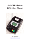
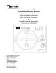
1
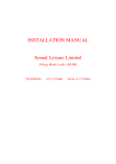
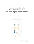
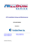
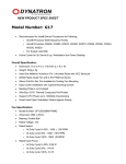
OPERATION & MAINTENANCE MANUAL
CELLULAR CDMA/GSM
REPEATER MODEL RPT 9000
Document Release Date: April 20th 2007
Document use is restricted to that described on the cover
1
Any modifications to this device will void FCC and IC approvals.
Document use is restricted to that described on the cover
2
Manual Number: RPT 9000
OPERATIONS & MAINTENANCE MANUAL
CELLULAR REPEATER MODEL RPT 9000
TELCOSAT RPT 9000
Model RPT 9000U UPLINK
Model RPT 9000D DOWNLINK
The information set forth in this document and all rights in and to inventions disclosed
herein, and patents which might be granted thereon disclosing, employing or covering the
materials, methods, techniques or apparatus described herein are the exclusive property
of Telcosat Inc.
This document is an operation and maintenance manual. No disclosure or reproduction of
the information or drawings shall be made of any other purpose without the prior written
consent of Telcosat Inc. Use of the information contained herein to fabricate or assemble
any item in whole or in part is expressly prohibited.
Any modifications to this device will void FCC and IC approvals.
Document use is restricted to that described on cover
TELCOSAT RPT 9000
SAFETY SUMMARY
High voltage is used in the operation of
this equipment. Death on contact may
result if personnel fail to observe the
following safety precautions:
•
Only qualified trained personnel can install this equipment. Electrical connection and installation
must meet your local Electrical Safety Installation codes.
•
Prior to any maintenance or inspection of this device disconnect the power supply.
•
Do not remove covers or access plates on the equipment unless you are a trained technician and
authorized to carry adjustment and maintenance for this apparatus.
•
When installing antennas always be aware of high voltage overhead power lines. Contact with
power lines will result in severe injury and or death.
•
To prevent electrical shock or damage to the equipment, do not operate the repeater until you
thoroughly understand the operation and function of all controls, indicators, and connectors.
•
The RPT9000 Repeater weighs approximately 45 lbs/ 22kilograms. The repeater must be attached
to the appropriate supporting device using the welded supporting lugs on the enclosure. The nuts
and bolts must be a minimum Grade 5, ¼” (6mm) diameter and corrosion resistant.
FIRST AID
In case of electrical shock:
THIS PERSON COULD STILL BE IN CONTACT WITH ELECTRICAL POWER. DO NOT
TOUCH THIS PERSON BEFORE YOU INSULATE YOUR SELF FROM THE ELECTRICAL
SOURCE.
•
Turn off the electrical power.
•
If you cannot turn off the electrical power, pull, push, or lift the person to safety using a dry
wooden pole, a dry rope, or some other insulating material. Do not use any metallic objects to
move this person.
•
After the injured person is no longer in contact with the electrical source, obtain/perform
immediate medical attention.
Document use is restricted to that described on cover
4
TELCOSAT RPT 9000
TABLE OF CONTENTS
TABLE OF CONTENTS
SAFETY SUMMARY-----------------------------------------------------------------------------------------------------------Page 4
FIRST AID------------------------------------------------------------------------------------------------------------------------Page 4
TABLE OF CONTENTS--------------------------------------------------------------------------------------------------------Page 5
CHAPTER 1
1.1 GENERAL
1.2 INTRODUCTION
1.2.1. MATERIALS
1.2.2 RPT 9000 APPLICATIONS
1.3 RPT 9000 SPECIFICATIONS
Page 6
Page 6
Page 6
Page 6
Page 7
1.4 TECHNICAL ASSISTANCE
Page 7
OPERATIONAL OVERVIEW
CHAPTER 2
2.1 GENERAL
2.2 REPEATER MODULE RF PATHS
2.3 DETAILED TECHNICAL RF SIGNAL PROCESSES
2.4 AC POWER DISTRIBUTION
Page 8
Page 8
Page 8
Page 9
Page 10
INSTALLATION
CHAPTER 3
3.1 WARNING
3.2 TOOLS REQUIRED
3.3 ANTENNA REQUIREMENTS
3.4 ANTENNA ISOLATION & COAX CABLES
3.5. INSTALLING YOUR REPEATER
3.6 POWER AND ATTENUATOR SWITCH SETTINGS
3.7 RSSI INDICATOR AND SIGNAL LEVELS
3.8 ALIGNING YOUR ANTENNA
3.9 ADJUSTING UPLINK POWER
Page 10
Page 10
Page 11
Page 12
Page 13
Page 14
Page 14
Page 14
Page 15
WARRANTY REPAIR
4.1 WARRANTY
4.2 LIMITED WARRANTY
CHAPTER 4
Page 16
Page 16
Page 16
EQUIPMENT STORAGE
CHAPTER 5
Page 17
APPENDIX A TECHNICAL SPECIFICATIONS TABLE ONE
APPENDIX A RF EXPOSURE LEVELS
APPENDIX B RETURN GOODS PROCEDURE
B2. Returned Goods Procedure
B3. Shipping Procedure
B4. Returned Shipments
B5. Repair / Return Status
Page 18
Page 19
Page 20
Page 20
Page 20
Page 20
Page 20
LIST OF FIGURES
Figure 1-1 RPT 9000 in a typical repeater remote site set up configuration
Figure 2-1 RPT 9000 UP and DOWNCONVERTER Blocks
LIST OF TABLES
Table 1- Technical Specifications
Document use is restricted to that described on cover
Page 7
Page 9
Page 19
5
TELCOSAT RPT 9000
CHAPTER 1
SCOPE
1.1 GENERAL
The TELCOSAT RPT 9000 Cellular Repeater (consisting of UPLINK and DOWNLINK
bidirectional system) contains operational and maintenance information. This manual consists of
four chapters and two appendices as follows:
•
Chapter 1 outlines the manual contents, with description and general application notes
•
Chapter 2 contains an operational overview and tune-up procedures (single and multi
carrier).
•
Chapter 3 contains installation procedures, packing and shipping instructions.
•
Chapter 4 contains the repeater warranty information
•
Appendix A contains unit specifications and environmental data.
•
Appendix B contains the return goods procedure.
1.2 INTRODUCTION
The TELCOSAT RPT 9000 is a bidirectional system consisting of UPLINK and a DOWNLINK
modules used in locations requiring coverage, where conventional communication systems
cannot reach, such as buildings, parking structures, tunnels and remote areas. The TELCOSAT
RPT 900 is designed to provide coverage by using reliable, high intercept components.
Adjustable RF Gain is provided in each direction of communication (donor to portable and
portable to donor) to compensate for attenuation losses of over air links. Throughout this manual,
the terms DOWNLINK and UPLINK are used. Downlink is the direction of RF energy from the
Base Station Donor to the Mobile or Portable Subscriber. Uplink is the path direction from the
Mobile or Portable Subscriber to the Base Station Donor.
1.2.1
Materials
The materials supplied with the Repeater are the Up and Downlink modules, amplifiers, power
supplies user manual.
1.2.2
Applications
The RPT 9000 cellular repeater can be used as part of a complete in building package or as a
stand-alone Cell extender in remote areas.
Planning details for a complete in-building system are not included in this document.
Document use is restricted to that described on cover
6
TELCOSAT RPT 9000
Fig. 1-1
Typical TELCOSAT INC remote location Site System
Fig. 1-1
1.3 RPT 9000 SPECIFICATIONS
Appendix A contains the TELCOSAT RPT 9000 Repeater Specifications.
1.4 TECHNICAL ASSISTANCE
Technical assistance on the TELCOSAT RPT 9000 Repeater is available through:
TELCOSAT Customer Service Center
Phone: 1-403-291-4031
Fax: 1-403-291-3059
Document use is restricted to that described on cover
7
TELCOSAT RPT 9000
CHAPTER 2
OPERATIONAL OVERVIEW
2.1 GENERAL
The TELCOSAT RPT 9000 provides service at cellular radio frequencies.
The operational overview is presented in Fig 1-1
Downlink RF signals from a donor cell site are routed through a pick-up antenna, through a
Diplexer then continues to be process by the amplifier chain. The RF is amplified for path and
cable losses and filtered to reject out-of-band IM products and unwanted radio signals. The
downlink RF is injected into a fill-in antenna (coverage antenna) for null-area coverage.
The Up-link signals from mobile units are received into the coverage antenna of the repeater. The
incoming signal then passes through a Diplexer, then amplified in the Up-link modules and
finally the power amplifier. The Up-link process is the same as the Down-Link process.
2.2 REPEATER MODULES
The Up-link RF path are isolated from the Down-link RF path by utilizing Cavity Band Pass
Diplexers and Saw Band-pass filters (BPF) that provide out-of-band rejection.
Figure 2-1 illustrated a simplified block diagram of the RPT 9000 Cellular Repeater.
Document use is restricted to that described on cover
8
TELCOSAT RPT 9000
Figure 2
2.3 Detailed Technical RF Signal Processes
A YAGI antenna with a certain directional gain provides the donor signal from the cell site, feeds
the band pass diplexer, and the downlink pre-amplifier which has low noise and a high intercept
point with a Gain of 20 dB. The Rx signal then passes through a UHF SAW filter and is then
down converted to a 70 MHz IF frequency filtered by a 25 MHz wide SAW filter. The 18 dB of
attenuation introduced by the SAW filter is compensated for, by a 40 dB gain (linear in dB) VGA
with AGC detector, chip amplifier.
The IF signal gain is controlled further more by digitally controlled attenuators for a total of 50
dB in 2 dB steps (See Figure 1-1).
The following converter section converts the IF signal frequency-true back up to the original Rx
frequency and adds additional 50 dB of gain with an IP3 of + 26 dBm. This section will provide a
+ 2 dBm maximum average output power (with CDMA modulation).
A +30 dBm Power Amplifier (PA) module follows to attain the targeted output power. The
module is using LDMOS RF amplifier mmic developed for ultra linear CDMA Multi-Carrier
applications. The third order intercept of this module is +50dBm typical.
Two modules, one for the uplink and one for the downlink paths of the repeater are employed.
They are electronically identical and their gain can be adjusted individually.
Document use is restricted to that described on cover
9
TELCOSAT RPT 9000
The repeater is set internally to a fixed 45dB of gain, plus another 50dB of adjustable gain is
available via the manual attenuator switches to make a combined total of 95dB overall gain. The
Up-Link and the Down-Link each have 95dB of gain.
Bar-graph Led’s in the up and down Link Modules are available for RSSI measurements for easy
set up of repeater sites.
2.4 AC POWER DISTRIBUTION
AC input power is through a power cord then a 2-pole on/off circuit breaker switch which feeds
two DIN rail mounted fuse holders with cartridge fuses rated at 1 AMP and 2 AMPS. The fuses
are replaceable and each DIN rail fuse holder holds a spare fuse. AC power from the DIN rail
fuse holders feed two DIN rail switching power supply units. The power supply units are
adjustable to operate on either 120 VAC or 230VAC. (Customer to notify Telcosat Inc with AC
power requirement prior to shipping)
The internal power supply units convert AC line voltage to DC power, one power supply unit
supplies 10volts DC and the other power supply unit provides 28volts DC. The DC power
provides all the necessary requirements for the active components.
CHAPTER 3
INSTALLATION
Any modifications to this device will void FCC and IC approvals.
READ THESE INSTRUCTIONS PRIOR TO INSTALLATION
DETAILED SET UP INSTRUCTIONS FOR YOUR RPT9000
CELLULAR REPEATER.
WARNING
DO NOT POWER UP THE REPEATER WITH OUT THE
ANTENNAS CONNECTED
3.1 WARNING
Cellular Repeaters should be installed by fully trained technicians. Improper
installation and excessive RF power levels can cause interference with the operation
of cellular towers.
Antennas must be mounted in a secure safe manner and according to safe working
practices. Lightning protection should be installed on every cellular repeater unit.
Document use is restricted to that described on cover
10
TELCOSAT RPT 9000
Antennas must not be installed near overhead electrical power lines as this can
cause serious injury and or death.
If you require any additional installation guidelines then please consult your
supplier or consult with an RF Systems Engineer.
3.2 TOOLS REQUIRED
Spectrum analyzer with a tracking generator, frequency ranges 1 Gigahertz.
Optional Signal Generator for onsite testing of the repeater, frequency range of 4 Gigahertz.
Hand held cable fault locator (TDR)
Multi-meter
Hand tools.
Water proofing tape.
Coax cable straps for support.
Cellular Phone.
3.3 ANTENNA REQUIREMENTS
ANTENNAS: please read your manufacturers antenna specifications before
installation. Your antenna will require a type “N” connection. The antenna, coax,
and fittings must be 50 ohms impedance.
The cellular repeater requires antennas that operate in the desired frequency range of the cellular
repeater. The RPT9000 Repeater has a frequency operating range of 824 to 849 Megahertz for the
up link, and 869 to 894 Megahertz for the downlink. Your antennas must operate within these
frequencies.
Failure to select the proper antennas will greatly degrade the performance of your repeater.
NOTE:
“UP-LINK” is the radio link from your hand held cellular phone to the cellular tower in the
frequency range of 824 to 849 Megahertz
“DOWN-LINK” is the radio link from the cellular tower to your cellular phone in the frequency
range of 869 to 894 Megahertz.
The repeater requires two antennas to be connected to the system. See image showing coax
connectors on the bottom of the repeater enclosure.
The Donor antenna is the antenna pointing to the Cellular Tower and the Area Fill antenna is the
antenna that provides the fill signal to your desired area.
Document use is restricted to that described on cover
11
TELCOSAT RPT 9000
3.4 ANTENNA ISOLATION & COAX CABLES
All repeaters require antenna isolation to prevent oscillation. The usable gain level of your
repeater is directly linked to the antenna isolation values. The maximum gain of your repeater
must be adjusted to 10 to15dBm lower than your antenna isolation values. For example, if your
antenna isolation value is 75dBm then your maximum usable repeater gain is 60dBm.
Due to the variations of system layouts and requirements it is not possible to have one procedure
that will suffice every installation. You are strongly advised to acquire the services of an RF
system designer to calculate your antenna isolation requirements.
Ensure that your antennas are at the maximum possible distance apart. Do not place antennas in
close proximity to each other.
Coax cables should be low loss 50 ohm, and suitable for 800 megahertz band frequency.
Antenna connections should be clean and moisture free. Do not spray lubricant into the
connectors as this prevents the signal traveling through the coax. Use a cleaning solvent that has
no oil and does not leave any residue. High quality oil-less contact cleaner is suitable.
All coax connectors must be water tight and wrapped with water proof tape. Any moisture in the
connectors will degrade or eliminate the signals.
PREPARING YOUR CELLULAR REPEATER
Figure 3
Document use is restricted to that described on cover
12
TELCOSAT RPT 9000
3.5 Installing your Repeater
The Telcosat Repeater weighs in excess of 40 pounds (20 Kilograms)
Make sure that your repeater is securely bolted to a suitable support. There are four welded steel
tabs on each corner that must be used to bolt your unit onto a suitable support system. You must
use ¼” diameter grade five steel corrosion resistant bolts with lock washers and securing nuts, a
total of 4 bolts and nuts/lock washers are required.
Bottom of enclosure showing antenna connections
Figure 4
Only when you have safely connected and installed your antennas and coax then proceed to the
next step. DO NOT CONNECT TO THE POWER SUPPLY.
Document use is restricted to that described on cover
13
TELCOSAT RPT 9000
3.6 POWER AND ANTTENUATION SWITCH SETTINGS
Open the door on the Repeater and you will see two modules with a row of switches on each
Module
The left side Module marked Donor, controls the power level that transmit back to the cellular
tower. The right side box marked Area Fill controls the power levels to your area fill.
The rows of switches have numbers engraved below each switch and above the switches the word
Attenuate are also engraved into the box.
When the switches are in the up position towards the word Attenuate this means the signal levels
are reduced. (Attenuate means to reduce the signal level). When you want to increase power you
toggle the switch down, to decrease power you toggle the switch up.
The numbers below the switches are calibrated in dBm. For instance, the switch numbered 20
means that if the switch is towards the attenuate side (toggled up) then the signal is reduced by 20
dBm. If the same switch is toggled down then the transmit power is increased by 20dBm.
3.7 RSSI METER AND SIGNAL LEVELS
Your Repeater is fitted with a RSSI (Receive Signal Strength Indicator) Your RSSI indicator is
located just above your row of attenuator switches and is displayed as green Led’s.
The right hand side RSSI window is your receive signal from the cellular tower. (Area Fill)
The left hand side RSSI window is your receive signal from mobile cellular phones.
(NOTE: THE RSSI INDICATOR DISPLAYS RECEIVE SIGNAL STRENGTH ONLY. THEY
DO NOT DISPLAY TRANSMIT POWER.)
The RSSI indicator has a dynamic range of -80 dBm to – 65dBm.
The green Led’s display will start to illuminate when a signal strength of -80dBm or greater is
received. When aligning your antenna to the cellular tower the RSSI meter must be monitored
during setup. When you rotate your antenna you will see the RSSI indicator increase and decrease
as you pass the signal with your antenna.
This RSSI window on the Area Fill side (Right Side Module) should not have all the green Led’s
displayed. If the Led’s are 100% green then this indicates that you have too much receive signal
from the cellular tower. The maximum required RSSI level is approximately 80% of the green
illuminated Led display bars.
3.8 ALIGNING YOUR DONOR ANTENNA TO A CELLULAR TOWER
It is very important not to have too much signal from the cellular tower on the
“Area Fill” input signal. Full bars on the right hand side green LED RSSI display
indicate possible signal excess.
Document use is restricted to that described on cover
14
TELCOSAT RPT 9000
Rotate your antenna until you pick up a cellular signal from a Cell tower. If the signal strength is
greater than -80dBm then the LED window on the Donor side will start to illuminate. Adjust the
antenna until the received signal is peaked. Check to see that the green Led display is not more
than about 80% illuminated. If you have 100% solid green lights on the right side display window
then you must reduce the receive signal level.
You can reduce the received signal level two ways.
1) Replace your Donor antenna with a lesser gain antenna.
2) If your system design will permit, slightly rotate the antenna away from the maximum signal
until the RSSI window reads about 80% of maximum display level.
After adjusting the receive signal levels from the Cellular Tower we now adjust the power levels
for the area fill. (Down-Link Signal)
For the next step you can use your cellular phone signal level indicator or preferably a spectrum
analyzer.
Toggle down the area fill switches in 2dBm steps until the desired power levels have been
obtained.
3.9 ADJUSTING UP-LINK TRANSMIT POWER TO CELLULAR TOWER
It is important to only use the minimum required power level for the Up-Link
transmit power. The required power level can be provided from a RF Systems
Engineer or appropriate RF Path Loss computer software.
CONNECT A SPECTRUM ANALYZER OR AN RF POWER METER TO MEASURE
MAXIMUM TRANSMIT POWER FOR THE UPLINK AND DOWN LINK CARRIER.
Maximum permissible RF transmit power is 3OdBm for a single carrier and 26.5 dBm for two
carriers.
Make a test call while the repeater is adjusted to the minimum gain on the Uplink Frequency
(824/849 MHz)
When making the test call on your cellular phone you must be a minimum of 30 metres (100ft)
from the area fill antenna.
If you cannot complete the call increase power in 2 dBm increments. Make a test call after every
adjustment.
NOTE: YOUR REPEATER HAS THE CAPABILITY TO BOOST SIGNALS
FROM AS LOW AS -104dBm. THIS IS BELOW THE RANGE OF YOUR RSSI
INDICATOR. USE A SPECTRUM ANALYZER TO LOCATE YOUR SIGNAL
Document use is restricted to that described on cover
15
TELCOSAT RPT 9000
If you find that you cannot detect any cellular signals using the RSSI indicator then
you must use an alternative method to locate the signal.
If you fail to locate a signal then you have the following possibilities.
1) There is no cellular service.
2) Faulty coax, connectors or antenna.
3) Insufficient antenna separation, (vertical separation/ horizontal separation)
4) Aimed to a competitor’s cell tower which does not service your cellular phone. This may show
full power on your cellular phone but will not connect to the service.
FOR TECHNICAL ASSISTANCE INSTALLING YOUR REPEATER PLEASE
CONTACT:
Telcosat Inc,
Calgary, Alberta,
Canada.
T2E 7E4
403 291 4031
Fax 403 291 3059
Email: [email protected]
NOTE: Local time, Central Mountain Time. (-7 GMT)
CHAPTER 4
WARRANTY AND REPAIR
4.1 WARRANTY
Your Telcosat Repeater is guaranteed against manufacturers defects for 120 days.
Telcosat Inc retains the right to decide if the fault/defect is a manufacturers defect.
Telcosat Inc will not accept liability for any damage caused through improper use or poor
installation practices.
4.2 Limited Warranty
Hardware. Telcosat Inc, or any subsidiary selling the Product (RPT9000 Cellular Repeater)
warrants that commencing from the date of shipment to Customer (and in case of resale by a
Telcosat Inc reseller, commencing not more than ninety (120) days after original shipment by
Telcosat Inc), and continuing for a period of the longer of (a) ninety (120) days or (b) the period
set forth in the Warranty Card accompanying the Product (if any), the Hardware will be free from
defects in material and workmanship under normal use. The date of shipment of a Product by
Telcosat Inc is set forth on the packaging material in which the Product is shipped. This limited
warranty extends only to the original user of the Product. Customer's sole and exclusive remedy
and the entire liability of Telcosat Inc and its suppliers under this limited warranty will be, at
Telcosat Inc or its service center's option, shipment of a replacement within the warranty period
Document use is restricted to that described on cover
16
TELCOSAT RPT 9000
and according to the replacement process described in the Warranty Card (if any), or if no
Warranty Card, as described, or a refund of the purchase price if the Hardware is returned to the
party supplying it to Customer, freight and insurance prepaid. Telcosat Inc replacement parts used
in Hardware replacement may be new or equivalent to new. Telcosat Inc obligations hereunder
are conditioned upon the return of affected Hardware in accordance with Telcosat Inc or its
service center's then-current Return Material Authorization (RMA) procedures.
EXCEPT AS SPECIFIED IN THIS WARRANTY, ALL EXPRESS OR IMPLIED CONDITIONS,
REPRESENTATIONS, AND WARRANTIES INCLUDING, WITHOUT LIMITATION, ANY
IMPLIED WARRANTY OR CONDITION OF MERCHANTABILITY, FITNESS FOR A
PARTICULAR PURPOSE, NON-INFRINGEMENT, SATISFACTORY QUALITY, NONINTERFERENCE, ACCURACY OF INFORMATIONAL CONTENT, OR ARISING FROM A
COURSE OF DEALING, LAW, USAGE, OR TRADE PRACTICE, ARE HEREBY EXCLUDED
TO THE EXTENT ALLOWED BY APPLICABLE LAW AND ARE EXPRESSLY DISCLAIMED
BY TELCOSAT INC, ITS SUPPLIERS AND LICENSORS. TO THE EXTENT AN IMPLIED
WARRANTY CANNOT BE EXCLUDED, SUCH WARRANTY IS LIMITED IN DURATION TO
THE EXPRESS WARRANTY PERIOD. SOME STATES OR JURISDICTIONS DO NOT ALLOW
LIMITATIONS ON HOW LONG AN IMPLIED WARRANTY LASTS, THE ABOVE
LIMITATION MAY NOT APPLY. THIS WARRANTY GIVES CUSTOMER SPECIFIC LEGAL
RIGHTS, AND CUSTOMER MAY ALSO HAVE OTHER RIGHTS WHICH VARY FROM
JURISDICTION TO JURISDICTION. This disclaimer and exclusion shall apply even if the
express warranty set forth above fails of its essential purpose.
Restrictions. This warranty does not apply if the Product or any other equipment upon which the
Product is authorized to be used (a) has been altered, except by Telcosat Inc, (b) has not been
installed, operated, repaired, or maintained in accordance with instructions supplied by Telcosat
Inc, (c) has been subjected to abnormal physical or electrical stress, misuse, negligence, accidents
forces of nature, earthquakes, lightning strikes, vandalism, and civil unrest.
CHAPTER 5.
Storage of Equipment
When storing your equipment you must place the unit in a dry location, away from direct
sun exposure and take measures to prevent moisture/condensation build up in your
repeater enclosure.
Silica Gel bags should be placed inside the enclosure to absorb moisture. The door on
the enclosure should be closed and sealed with weather proof tape to ensure an air tight
enclosure.
The silica gel bags should be changed /inspected at regular intervals to ensure proper
functionality of the material.
You are strongly advised to seek the advice of a professional company that has expertise
in long term preservation techniques of electronic equipment.
Maximum storage temperatures of your Telcosat Repeater is +50c (122F)
Minimum storage temperature of your Telcosat Repeater is -40c (-40F)
Document use is restricted to that described on cover
17
TELCOSAT RPT 9000
APPENDIX A
TECHNICAL SPECIFICATIONS
Specifications for the Telcosat Repeater system CDMA/GSM Model RPT9000
Frequency Range:
Overall systems Gain
Pass band ripple:
Channel ripple:
Group Delay Variation
Absolute Delay:
Phase linearity
Rx Noise figure @ maximum
Gain:
IMD 2 tone :
IMD 4 tone:
Power output @ 1dB gain
compression:
Antenna Impedance Rx and
TX :
Max SWR in/out:
Manual Gain Control user
enable:
Spurious outputs:
Power Supply:
Operating Temperature
RF Connectors:
Mechanical Specifications:
Weight:
Enclosure type:
Down link 824-849MHz / Up-link 869-894MHz
(3dB Pass Band):110dB min. for 15db S/N
+/- 2.5dB max. within 3dB Pass Band
.2dB max.
90% of 3db Bandwidth typical: 65 nsec
Less then 2. Micro sec.
90% of 3 dB Bandwidth: typical 9.2 deg
3.7dB typical
51 dBc typical
48 dBc typical
+ 30dBm RMS ( up and down link)
Z= 50 ohms
1.5 to 1 max
50dB total in 2db steps
55dBc max
28VDC/140Watts or 90 to 260 AC / 150 Watts
consumption
-20 to+60 C
N- Type Female
Size: 14.5" x 16.5" x 11.5" 36 x 41 x 29 cm
40 pounds/ 20Kg typical
NEMA 4A, 12
Table 1
Nominal Pass-band Gain dB= 95dB
Nominal band width Uplink 824/849 MHz = 25MHz
Nominal band width Down-Link 869/894MHz = 25MHz
Input and Output Antenna Impedance = 50 ohms
Rated mean out-put power = +30dBm
Document use is restricted to that described on cover
18
TELCOSAT RPT 9000
NOTE RULE: RSS-133 section 5.3
The manufacturers rated output power of this equipment is for single carrier operation. For situations when
multiple carrier signals are present, the rating would have to be reduced by 3.5dB, especially where the output signal is re-radiated and can cause interference to adjacent band users. This power reduction is to be by
means of input power or gain reduction and not by an attenuator at the out-put device
FCC/IC RF Exposure Requirements
The antenna(s) used for this transmitter must be installed to provide a
separation distance of at least 65.9 cm (25.94 inches) from all persons, and
must not be co-located or operating in conjunction with any other antenna
or transmitter.
Any modifications to this device will void FCC and IC approvals
Document use is restricted to that described on cover
19
TELCOSAT RPT 9000
APPENDIX B
RETURNED GOODS PROCEDURE
B1. Technical Information
Contact Telcosat Inc or your supplier to determine whether or not an item should be returned for
repair.
Contact Telcosat Inc 403 291 4031 or email, [email protected]
B2. Return Identification
Please provide the following information with each repair.
1.
2.
3.
4.
5.
6.
7.
Date of requested repairs.
Customer name with full address for returning goods
Contact person responsible for returning the product for repairs
Client telephone number
Serial number (serial number is located on the exterior heat sink)
Original purchase date
Reason for return.
B3. Shipping Procedure
Ship all returned goods PREPAID to the following address:
Product Repairs,
Telcosat Inc,
Bay 116 1919 – 27th Avenue NE,
Calgary, Alberta,
Canada. T2E 7E4
Telephone 403 291 4031
Fax 403 291 3059
Email: [email protected]
Your commercial invoice must state REPAIR/RETURN. Failure to provide proper Commercial
Invoices may result in taxes and duties which will be charged back to the client.
B4. Return Shipments
All returned shipments will be sent PREPAID, to the customer’s indicated address.
Any extra packaging material will be charged back to the client.
B5. Repair / Return Status
Under normal circumstances defective items will be replaced repaired with in 5 working business
days of receipt.
Telcosat Inc will inspect and test your repeater in a lab environment. Upon completion of the
inspection a written estimate will be provided to the client. A minimum charge of $500.00 will be
charged to the client to cover the cost of inspection and testing plus minor repairs.
Document use is restricted to that described on cover
20
TELCOSAT RPT 9000
XPANDAcell - www.xpandacell.com Toll Free: 1-888-785-7393 - Int'l: 1-951-694-1173 [email protected]
Document use is restricted to that described on cover
21