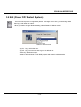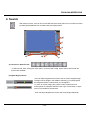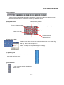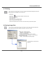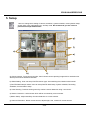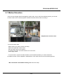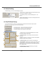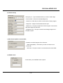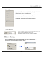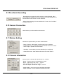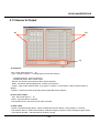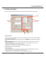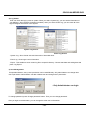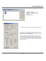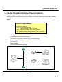
1
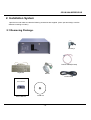
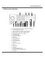
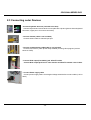
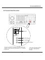
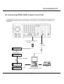
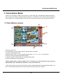
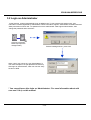
CDVS-5400 SERIES DVR
1. Precautions
Cautions & Warnings
- Be sure to turn off the power before installation.
- Avoid rough handling or mechanical shock.
- Keep off 20 cm distance with other machines or electronic products.
- Keep away from direct rays of the sun or heater or similar devices.(it causes fire)
- Don’t put things such as vase, cup, cosmetics, bottle etc. on this product. (it causes fire, an electronic shock
hazard or an injury by falling)
- Don’t block the ventilating holes of this product with a kind of metal(ex : coins, hairpin, metal plate etc.) or
inflammable stuff(ex : match, paper etc.).(It causes malfunction of the product, fire and electronic shock hazard.)
- Don’t put a heavy-weight things on this product.(It causes an injury by falling)
- Fully insert power plug at outlet. (Uncertain connection causes fire.)
- Wipe smoothly with using dried cloth to clean the product. Don’t use any chemical products or detergent. This
may change the color of the product and spoil its surface .
- Stop using and turn off the power when odd smells or smokes comes out from the product. Then call your
nearest customer service. (continuous using may causes fire, an electronic shock hazard.)
- Don’t touch the power plug & cable with wet hand. (It causes electronic shock hazard.)
- Don’t pull power plug out by force. (Damaged power plug causes electronic shock hazard.)
- Keep away from the place of dust, humidity, soot when you install. These may cause malfunction of the product.
Be place dehumidifier near the product, remove dust from the fan of ventilate holes with compressed air every 3
months.(Dust & others may cause fire and electronic shock hazard.)
- Replace or clean front filter once of 3 months.
- Don’t drop or impact to the product.
- Keep this product away from strong magnetic fields or mechanical vibration.(It causes malfunction)
- Don’t install the product to extremely cold place.
- Install the product well-ventilated place.
- Don’t open the cover of product at your disposal. (It causes fire, an electronic shock hazard.)
- Don’t change the power supply switch at your disposal. (It causes malfunction and damage)
- Don’t press the product when front door open. (It causes transformation or damage of Front Door.)
- Put another supportable stuff not to damage BNC board. BNC board could be broken or damaged by the weight
of BNC cable.
- It causes danger of explosion if battery is incorrectly replaced.
- Replace only with the same or equivalent type recommended by the manufacturer.
- Dispose of used batteries according to the manufacturer’s instructions.
- Adjust power input switch correctly.(110V or 220V)
- Use stable transformer where expected unstable power supply.
- Ask your customer service when you add more devices on this product(ex: HDD, Back-up device)
-2-
CDVS-5400 SERIES DVR
2. Installation System
Open the box and make sure that the following accessories are supplied. (Some part and design could be
different according to model.)
2.1 Removing Package.
Doorkeys
NetSafe DVR
Pan/Tilt Cable(RS-485)
Keyboard
Mouse
Power Cable
User’s Manual
User’s Manual
Install CD
-3-
CDVS-5400 SERIES DVR
2.2 Rear panel of System
a
e
f
g h
i
b
j k
lm n o p
c
d
q
r
a. Camera Input (CH1~CH16) / Output (CH1~CH16)
b. Camera 75Ohm Terminator
c. Control Output (Com:4port, Control:16port)
d. Sensor Input (Com:4port, Sensor:16port)
e. AC Power Input (AC 110 ~ 220V)
f. PS/2 Mouse Port
g. PS/2 Keyboard Port
h. USB Port
i. Com A Serial Port
j. LPT(Printer) Port
k. Com B Serial Port
l. Line Out 1
m. Line In / Line Out2
n. MIC In
o. Game Port
p. VGA Out
q. TV Out (Composite Out)
r. RS422/485 (RX Connection Port)
s. LAN Port
-4-
s
CDVS-5400 SERIES DVR
2.3 Connecting outer Devices
- Connect keyboard & mouse (included in the box)
Connect keyboard and mouse at the correct place like a picture.(picture shows keyboard
connection, upper port is for mouse connection)
- Connect Camera (cable is not included)
Connect camera cable to channel input port.
- Connect communication cable(cable is not included)
Connect LAN cable or public phone line(if installed) for using client program (such as
center & i-DVR).
- Connect RCA output(if available) jack & Pan/Tilt cable.
Connect RCA output jack line for outer monitor and Pan/Tilt camera control cable.
- Connect Power supply cable
Connect power supply cable. Check again Voltage switch before connect cable.(110V or
220V)
-5-
CDVS-5400 SERIES DVR
2.4 Connect Pan/Tilt control
485
Signal Line (+)
a ground
Signal Line (-)
RX LED (Green)
TX LED (Red)
Operation LED (Green)
- Connect to PAN/TILT Receiver (RS-485 Signal line)
- Caution : When connect, pay attention (+), (-) polarity
of signal line
-6-
- Only when Operation LED is
‘On’ state, image appears
normally.
CDVS-5400 SERIES DVR
2.5 Connecting PSTN, ISDN, Leased Line & LAN
Following picture shows how you connect to a communication line. It shows about LAN connection and
PSTN (external modem). When you have modem in your system, you don’t need to use COM2 port for
connection.
Connecting to COM 2 port
( 9 PIN )
LAN port
Ethernet
A/C ADAPTER
RS-232(25Pin)
D.S.U(Modem)
Leased Line (ISDN)
D.S.U(Modem)
A/C ADAPTER
COM2
Printer
Client pc for Remote control
-7-
CDVS-5400 SERIES DVR
2.6 Connecting Loopback output (Camera 75 Ohm Terminator)
Each channel’s current input image can directly out to monitor by ‘Ch out’ port. 16 ch outputs are available.
To use this function, connect cable then adjust dip switch.
ON
ON
- ‘On’ : not connected outer monitor.
- ‘Off’ : connected with outer monitor
1 ----------------------------------------------------16
- For a normal image output of each channel, adjust dip switch as ‘On’ status when there are no connection
with monitor.
2.7 Connecting Control Output
COM
Control Out ( 1 ~ 16)
Con.
Siren, Alarm, Outside Relays
(-)
(+)
External Power Supply ( DC 12V)
When a sensor triggered or motion detected, warning or alarm signal is output through the each port of control
out.(need to setup before using. See P35). If devices connected correctly, it works by the output signal from control
out port. (See the picture for connection)
- Use 12V, below 300mA. For controlling lights or other devices, use another external relay.
2.8 Connecting External Sensor
COM
Sensor Input ( 1 ~ 16)
Sen.
16 sensor connections are available. Usually sensor’s one of signal lines connect to com port and connect the
other signal line to a desired sensor input port(1-16).
- Set “NC”, “NO” Type at setup menu.(see p35)
- No power supply from the product. Use individual or provided power for each sensor.
-8-
CDVS-5400 SERIES DVR
3. Surveillance Mode
When every connection is made, turn the power on. After loading OS, it automatically starts DVR program.
Initial screen is surveillance mode(see the picture below). In surveillance mode, it shows real time images of
each channel from a connected camera. Also user can control other functions with using function buttons.
3.1 Surveillance screen.
b)
c)
a)
d)
e)
g)
f)
a) Shows current user.
b) Function Button : search, setup, backup, Pan/Tilt control, exit button.
c) Shows Current date and time.
d) Select Screen division : icons for selecting whole screen, 4, 6, 7, 8, 9, 10, 13, 16 ch division.
e) Shows currently recording HDD partition status.
f) Shows connected control & sensor ‘s working status.(on/off)
g) Shows IP address of connected user’s.
* When program starts, it login as ‘default’ user. To add users or to use all function, must re-login as
‘Administrator’ (ID : Administrator, Password : none). See detail at 3.2.
- Initial screen division is set as 4 screen division. When system restarted by unexpected power failure or by
force, it remembers last information of screen division then shows last screen division.
-9-
CDVS-5400 SERIES DVR
3.2 Login as Administrator
At the first time, program automatically login as default user. To use program with another user, user
information must be registered by Administrator. When DVR starts, login as ‘Administrator’ and add users and
allow permissions of each user. No password is set to Administrator. After login as Administrator, then
change the password and memorize it.
Click one of function
buttons.(except Auto
change button)
If above message shows , press ‘Yes’
When ‘User Login’ shows up, type ‘Administrator’ in
user name and press ‘Ok’.(No password at first time)
After login as ‘Administrator’, Now user can use every
function of DVR.
* You can add user after login as ‘Administrator’. For more information about add
user see 5.14 e) on this manual.
-10-
CDVS-5400 SERIES DVR
3.3 Controlling Screen Division
When user clicks one of following buttons, screen display will change as selected division.
• 4A : Display the screen 1ch ~ 4ch
• 4B : Display the screen 5ch ~ 8ch.
• 4C : Display the screen 9ch ~ 12ch.
• 4D : Display the screen 13ch ~ 16ch.
• 9 : Display the screen 1ch ~ 9ch.
• 13 : Display the screen 1ch ~ 13ch.
• 16 : Display the screen 1ch ~ 16ch.
• 6 : Display the screen 1ch ~ 6ch.
• 7 : Display the screen 1ch ~ 7ch.
• 8 : Display the screen 1ch ~ 8ch.
• 10 : Display the screen 1ch ~ 10ch.
• If you press this button, all button disappears and entire screen displays. To return to
a previous mode, click right mouse button again.
3.4 Instant Recording in Surveillance mode
If system schedule set as ‘No recording’ or ‘Motion mode’, no images are recorded without motion. Use this
function when user need to record a image regardless of system schedule.
Although in continuous recording mode, user can use this function to mark suspicious part.
- How to use
- Move mouse and click right mouse button.
- Then ‘Instant’ caption shows up on top of right screen.
- To release, double click right mouse button.
* You can’t use this function without setting the frame on ‘Recording Schedule’ at Setup.
-11-
CDVS-5400 SERIES DVR
3.5 Screen Auto Switching
To use Auto Switching, click the button(left picture) in a surveillance mode. When you click
this button, the divided screen switches automatically. You can set switching time at the
setup.(Auto switching is available on 1, 4, 9 division)
- How to use Auto Switching
1. Choose screen.(1, 4(a,b,c), 9 division)
2. Click auto switching button
3. To stop, click auto switching button again.
* For entire screen mode, click entire screen icon after clicking auto switching button
- 1ch
1
Double click left mouse button
16
Click
- 4ch
1
3
2
4
Choose Mode
13 14
15 16
Click
- 9ch
1 2 3
4 5 6
7 8 9
Click
Choose Mode
-12-
10 11 12
13 14 15
16 8 9
CDVS-5400 SERIES DVR
3.6. Backup
The icon left is backup button. If this button is pressed, following picture shows up. This function
uses for moving a stored image data from local HDD to other backup media. User can backup
image data to other portable media or other HDD. Available backup devices are DVD-RAM, CDRW and IEEE1394 devices.
- How to backup
- Press backup button, following dialog shows up.
- Select date and 10 minute data block.(if selected it turns red)
- Select backup media. (Backup medial should be installed)
- Press ‘Start Backup’ button.
a)
b)
c)
Format IEEE1394 connected external HDD.
d)
a) Error Msg : Show error messages. If selected data is more than available space it shows error message.
b) Calendar : Red for current date, reversed for data stored date.
c) Select Backup Media : Shows available backup devices(when check ‘Fixed disk’, it shows installed local
HDD list.)
d) Time table for selected data. Each block contains 10 minutes’ data.
-13-
CDVS-5400 SERIES DVR
3.7 Controlling PAN/TILT Camera
If the PAN/TILT camera installed, you can control camera with following remote control. To do
this press the PAN/TILT remote control button(picture in left) then you can control camera.
Available function may be varied according to camera.
- Direction Control
To control camera direction, use arrow buttons. The number in the
middle of circle shows currently selected camera number. To change
this, click camera image from surveillance screen. If no PAN/TIL
camera installed this will not available.
- Zoom & Focus Control
Using arrows, user can Zoom in/out and adjust focus manually. If your
camera doesn’t support these, you can’t use these function.
- Control additional devices
User can turn on/off the power of WIPER, LIGHT with click button.
When you press ‘TOUR’ button, the camera moves to the preset
location(Location and other control should be set before use this
function), These function subject to the function of camera.
- Preset Control
To use preset control, user should preset the position in “Pan/Tilt Detail settings’. This function enables
your camera automatically moves to the position where you set before. User can use this function when he
needs to watch more than one area with one camera.
-14-
CDVS-5400 SERIES DVR
3.8 Exit (Power Off/ Restart System)
The button like a picture is a logout(exit) button. To change current user, you should log off and
then log on with other user name.
When you need to change Windows setting, select ‘Restart in Window mode’.
Restart in Windows Mode
- Log On : Log on with other user.
- Log Off : Log off current user and Log on with default user.
- Power Off : Shut down system.
- Restart System : Restart System.
- Restart in Window Mode : Finish DVR program and restart in windows mode.
-15-
CDVS-5400 SERIES DVR
4. Search
With search function, user can find a recorded data more easily than VCR. Our search function
provides special features such as Index search & Object search.
g)
f)
e)
d)
a)
b)
c)
a) Functions in Search mode
In search mode. Print, Saving file, Index search, removing after image, object search and Thumb nail
preview are available.
b) Adjust Bright & Zoom
User can adjust brightness and screen size of current stopped image.
To adjust current image in the middle of searching, you should pause
the image and select a camera then you can adjust it.
To zoom in current image’ part, pause current screen and move
mouse pointer to a desired area then click ‘right’ mouse button, 5 steps
zoom in is possible for pointed area.
- User can adjust brightness of screen with using ‘Bright’ adjust bar.
-16-
CDVS-5400 SERIES DVR
c) Select Camera
Select camera number, date & time before start search. To select more than one camera, you can
use screen division button or choose each cameras you desired to watch.
d) Playback buttons
Frame by frame playback
button(Clockwise)
Frame by frame playback
button (counterclockwise)
Playback button(clockwise)
Stop button
Move to the start
of frame
Move to the end of frame
Counterclockwise
playback button
e) Date, skip & delay
Select a button like a picture then a calendar shows up on your screen. Red
color is current date and reversed date means that there are recorded images of
that day. Select a date and press ‘Ok’.
-Delay : set delay time for playback(higher value(50)).
-Skip : Set the number of frame to skip
f) Adjusting Time
User can adjust Time and minute of stored data with
using scroll bar like a picture.
g) Select Screen
1, 4, 9, 16 screen selection is available in
search mode.
-17-
CDVS-5400 SERIES DVR
4.1 Printing
User can print out current image. To print out a image, stop the desired image then press print
button.(If printer is not installed, you can’t print out.)
- Install printer
- Press ‘Exit’
button and select ‘Restart in Window mode’
- Press ‘Start’ then ‘setting’.
- Press ‘Add Printer’
- Press ‘Next’ in print installation Wizard
- Select ‘Local Printer’ then press ‘Next’.
- Choose correct printer driver in the list or use a driver when you purchase a printer.
4.2 Saving Image files
User can save current image as Jpeg or AVI format. To save image, press save button and
check export type and choose a director to save files. Press ‘Ok’ to save.
- Export Type : Choose file format.
- JPEG File : current stopped frame
- AVI File : moving pictures.
- AVI detail setup(available when ‘AVI file’ checked)
- AVI duration from current frame(sec) : choose a time to
export from current image.
- Quality : choose Quality of exporting images.
Choose directory to save files and
press ‘Ok’.
-18-
CDVS-5400 SERIES DVR
4.3 Index Search
User can search a recorded image by Index search. User can search a recorded image by
sensor, motion, instant recording with this function.
- Select Camera : Select camera number.
- Select sort option
- Sensor : shows image list recorded by sensor
- Motion detection : shows image list recorded by motion
- Instant Record : shows image list by Instant recording
- All event : Shows all list of index recording.
Select option above picture then, following picture shows up. Select a recorded image
in list then you can play it.
-19-
CDVS-5400 SERIES DVR
4.4 Search Backup data
User can search a recorded image from a backup media. When user select a backup device, it
shows contained data list like a following picture.Choose one of them to playback.
- Backup Media : Shows available backup media.
-Fixed HDD : Shows installed HDD list in the system. If not selected it
shows installed external backup devices.
- Choose Start hour : Show the recorded data list from selected device.
Press ‘Ok’ button to playback selected image.
4.5 Filtering Afterimage
This product records 3 kind of resolution. In 720x480 resolution, because of its high speed
recording occurs afterimages when there is a high speed movement. This function filters this
phenomenon and shows clear image.
Afterimage
After filtering
-20-
CDVS-5400 SERIES DVR
4.6 Thumbnail Preview
User can easily find out changed image by this function. This function shows recorded image
data by break down in time, 10 minute, every minute.
- How to use
- Select date from a calendar and select camera.
- Press ‘Thumbnail preview’ button.(If camera is not selected, camera 1 is default.)
0 1 2 3 4
5 6 7 8 9
10 11 12 13 14
1
2
3
1
2
3
4
4
5
6
5
6
7
8
9
10
15 16 17 18 19
20 21 22 23
By Time
By 10 min.
By 1 min.
- User can playback, after choose 1 min. data.
- To move previous screen, click right mouse button.
4.7 Object Search
This function allows you to find a changed image in a specific area.
- How to use
- Choose key frame image : At search mode, you may stop at certain image. The object search
function use this image as key frame.
- Press ‘Object search’ button, after get key frame.
Object Search button
-21-
CDVS-5400 SERIES DVR
- Object Search Dialog
-Dialog box shows up like a following picture.
-Checked Frames : number of compared frames
in total.
-Time : Time value of the checked frame.
-Found : Number of detected frames from key
frame.
-[Start Search] : It will show you filter dialog and
start to find.
-[Clear Selection]: clear rectangle selection of
object
-[Stop] : it will stop searching operation.
-[Apply to main search] : load current information
to main search mode to do other operation such
as zoom.
-[Cancel] : stop and close the dialog box.
-List Box : It will display detected image
information, clicking will display the image as full
screen.
-Select to object to detect
Simply press down the left mouse button and drag until you reach the area you want to select. It will shows
you striped rectangle as follows.
You can move an resize the rectangle.
-22-
CDVS-5400 SERIES DVR
-Search Filter
User can add some search filters to make it easier.
-Start Time : It will be automatically loaded from the key
frame information.
-End Time : End time(10 min. default) it could be the
future and the past.
-Sensitivity : 1-20 sensitivity option, higher number is
more insensitive (default : 3)
-Show detected image : It will show all image of the
selected region, it make slower to reach.
-Found Image
If there are any detected image, those will be displayed at the list box as follow. Clicking or moving with arrow
key will display the image as full screen mode.
Press [Apply to Main Search] button to load this image to main Search mode.
-23-
CDVS-5400 SERIES DVR
5. Setup
User can change each setting of camera, resolution, system schedule, communication setup,
sensor setup, user management etc. at setup mode. We recommend you don’t allow a
permission except Administrator.
g)
f)
a)
e)
d)
b)
c)
a) Choose camera : Press camera number, then it shows current capturing image with its resolution size.
Above picture shows 360x240 resolution.
b) Global Setting : User can setup Pan/Tilt receiver type, Auto switching time, Motion Index Interval.
c) Pan/Tilt Detail setup & others: User can setup Pan/Tilt detail setup, System schedule, Recording
Schedule, Communication setup.
d) Voice Warning : Produce warning sound by motion & sensor detection using *.wav sound..
e) Sensor Connection : select sensor which will be connected by current camera.
f) Motion Setup : Adjust sensitivity of motion detection on current camera.
g) Camera Information : Name current camera, adjust bright, Hue, contrast of current camera.
-24-
CDVS-5400 SERIES DVR
5.1 Motion Detection
User can record image when there happens motion event. As you see in the following picture, you can set
5 motion areas in each camera.(System schedule should be set as motion recording.)
Striped areas are motion area
- How to set motion area.
- Select camera you want to motion recording.
- Select area expected motion events
- Can set motion area up to 5 regions.
- To erase motion area, move the motion box out of screen.
- Press ‘Apply’ button.
- To record motion, system schedule should be set as ‘Motion Recording’. If motion detected in
surveillance screen, red box appears in detected area. Then OSD color turns red as following picture.
- More information about Motion Setting, see 5.11. & 5. 14 a).
-25-
CDVS-5400 SERIES DVR
5.2 Global Setting
In Global setting, you can set overall settings of camera.
- Receiver Type : Set type of protocol of Pan/Tilt Camera. Only
one protocol is available in a system.
- Auto Switching Time(s) : Set auto switching time 1- 100
second.
- Motion Index Interval(s) : Set motion recording index interval
when you do index search.
5.3 Pan/Tilt Detail Setup
To use Pan/Tilt function in camera, you should select connected camera and then check ‘Pan/Tilt
Connection’. For more setup, press ‘Pan/Tilt Detail Setup’.
- Pan/Tilt Connection : Check Pan/Tilt Camera Connection
- Pan/Tilt Detail Setup : Button for Pan/Tilt Detail Setup.
- All Camera Setting : Set all camera as current setup.
a)
- Available function in Pan/Tilt Detail Setup may be varied
according to Pan/Tilt camera type.
e)
b) Speed : Depends on camera type. Set the moving speed
of Pan/Tilt, Zoom & focus of camera.
b)
d)
c)
a) Camera Control : Test currently connected camera’s
movement.
c) Address Setting : Set the camera’s connecting port.
d) Preset State : Set the area you want to see. User can set
10 preset areas. To set the area, choose number in ‘Preset
status’ and move your camera with using control button, then
press ‘Setting’ button.
e) Preset & Tour : Set the speed & timing of Preset &
Tour.(Only available camera)
-26-
CDVS-5400 SERIES DVR
5.4 Recording Schedule
User can set the resolution and numbers of recording frame. Following picture shows ‘Recording
schedule’ dialog.
a)
g)
b)
c)
d)
e)
f)
a) Frame Status : Show recording frame status per second. If the box is full, you can’t add more frame in
camera. (This is not a display of HDD capacity)
b) Camera # Frame : Shows camera number and currently set the number of recorded frame.
c) Set Default : Set all the camera’s value as default.
d) Resolution : Set resolution.(720x480, 720x240, 360x240 : NTSC, 720x576, 720x288, 360x288 : PAL)
e) Quality : choose the quality of recording image(Superfine, Fine, Normal, Low are available) Superfine :
High quality image but low compress rate. Low : Low quality image but high compress rate. .
f) Sensitivity : Our image compressing program minimize by getting only changed area from currently input
images. If sensitivity value is high it works more sensible on image changes and shows very clear image
when you playback.
-27-
CDVS-5400 SERIES DVR
5.5 System Schedule
a)
d)
b)
c)
a) Days of Week : Set each day’s schedule of system
-Single Selection Mode : Set different schedule
everyday.
To adjust same schedule in everyday,click
‘Single Selection mode’ then it asks you ‘All
day’s information of schedule will change as
current state, will you change this?’ . Then
press ‘Yes’ button
Then everyday checked and button changes to
‘Multi selection Mode’. Now you can see every
day's system schedule changes to current
state.
b) Recording Status : Shows time table of current recording schedule.
- To change current system recording schedule, select time you want to recording and click one of
recording modes. (No recording, Continuous mode, Motion mode)
- No Recording : Nothing is recorded, only surveillance.
- Continuous Mode : Records image continuously.
- Motion Mode : Records image when there is a detected motion.
-28-
CDVS-5400 SERIES DVR
c) Special Day Mode
This mode enables you set a special day setting(ex : holiday) in a week. User can adjust a different system
schedule on a specific date. To change to a special day mode, press ‘Normal day mode’ button. Choose
date and set time schedule and then press ‘save special day’ button. Saved day shows in a list box, this
schedule will be used on a saved day.
-Delete Special Day : Delete saved special
day.
- Save Special Day : Add special day to a list.
If setting is over, press ‘Ok’ button.
d) System Restart Time
User can set reboot or off time of system everyday.
- Enable : Check when you need to enable rebooting
- Time : Set reboot time of system.(by 10 min.)
- Restart : Restart system on a designated time.
- Off : Off system on a designated time.
-29-
CDVS-5400 SERIES DVR
5.6 Intensive Recording
The function Intensive recording uses a different setup for a specific time(for motion,sensor event) of
recording. For example, camera ch 1 is set as 10 frame & 360x240 in usual time and intensive
recording setup is 720x480, 20 fps. When a sensor & motion is detected, it records as you set in
intensive recording.
-Holding Duration : Set the recording time for intensive recording.
-Intensive On Sensor : Check this option when you need to use sensor detect recording.
5.7 Communication Setup
To use remote client program(Center program, I-DVR), you need to set this.
f)
a)
e)
b)
c)
d)
a) Disable Remote Control : If this checked, connection is not available.
-30-
CDVS-5400 SERIES DVR
b) Network Setup
-Emergency IP : Type IP address where you want to send image.
-Timeout Value : Set timeout value(waiting time)
- Center Port : With this port, DVR communicate to Center program.
- Image Port : Images are transmitted with this port.
- Search Port : This port is used when Center Program communicate
searched images with site DVR.
- Emergency Port : This port is used for transmitting images to the
emergency agent.
c) Web Function(iDVR : Internet DVR)
Enables to use iDVR program from client site.
- Web Viewer(iDVR) : check when you allow connection from
remote site.
- iDVR Port : This port is used to communicate with remote iDVR.
d) NDMS Control
Check when you use NDMS control system.
-31-
CDVS-5400 SERIES DVR
e) PPP Setup
This is used when you need to send emergency image through public phone
line.(Very low speed, we recommend you to use leased line.)
- Use PPP : Check whether you use PPP or not.
- Password & Confirm : Input password for connecting to PPP network.
- Phone Number : Telephone number you will use to connect.
- Modem Select : Select modem.(If none installed, it show ‘N/A’)
f) Quality & Resolution
Choose quality and resolution of image you will send to remote client.
- Quality : 3 steps available (Fine, Normal, Low)
- Resolution : Resolution 180x120 , 360x240 are available.
5.8 Voice Warning
When you need to warn using recorded wave file, you can use this function. If you set a wave file as
warning sound, designate sound comes out through speaker when motion or sensor detected.
To use this, you need to install sound card and select *.wav file.
- Select wave file
Click ‘Folder’ icon
Select *.wav file where it exists.
-32-
CDVS-5400 SERIES DVR
5.9 Pre-Alarm Recording
Records previous image from when sensor & motion detected. Max 1
minute setting is available. If you set 5 seconds, it records images from 5
seconds before when sensor & motion detected.
- When index searching, this data marked with ‘P’ letter. And ‘Pre-Alarm’
message shows up.
5.10 Sensor Connection
Check sensor you will use with current camera.
5.11 Motion Setting
Choose how system warns you when motion detects.
- Beep on Detect : Make ‘Beep’ sound through inner pc speaker.
- Full Screen Pop up : Shows full screen of detected camera for a while.
- Alarm Output : Operate connected alarm.
- Sensitivity : Set sensitivity of motion detection.(Low 5-High 50)
- Clear Motion Area : Clear all the motion area of current camera.
5.12 Camera Information
Set the name of camera and adjust bright, hue, contrast.
- Name : Type the name to be displayed on screen.
- Bright : Adjust bright with using +, - buttons.
- Hue : Adjust Hue with using +, - buttons.
- Contrast : Adjust contrast with using +, - buttons.
- Adjust Default : set current camera as default information.
- Adjust All Default : set all cameras as default information.
-33-
CDVS-5400 SERIES DVR
5.13 Sensor & Output
a)
b)
c)
a) Set Sensor
-Use : check external sensor 1 ~ 16.
- Type : Set type of sensor. To change type just click each buttons.
- ‘NO(Normal Open)’ type on usual time.
- 'NC(Normal Close)’ when control output.
- Record : set number of record frame when sensor detected.
- Delay : Set sensor detecting delay time. It works by the second.
- Output : Type control output number. If you type 4 on sensor 3, control button 4 will work when sensor 3
detects.
- Duration : Set the time value of ignoring sensor signal after sensor detects.
b) Set Control output
- Use : Set control output 1 ~ 16.
- Name : Type the name of controller .
- Auto ON/OFF Time : Set on/off time for each controller.
c) Other setup
- Sensor # for Alarm Output (Siren) : When external alarm sensor detects, control output no. 16 works.
- Transmission Sensor : When sensor detects, it delivers images to client PC where emergency agent works.
- Transmission Duration : Set transmission duration of image.
-34-
CDVS-5400 SERIES DVR
5.14 Site Information
User can find information of current system, site information, drive information etc. at this dialog.
b)
c)
a)
d)
e)
a) Site Information
- Site Code : Put site code at here. If this code is not matched with remote client program(center program),
you can’t logon from remote site.
- Display Sensor Status BAR : Check whether system shows ‘SENSOR’ when sensor detects in display
mode.
- Display Motion Detection Area Box : Check whether system shows red motion area box when motion
detected in display mode.
- Display Control Status BAR : Check whether system shows control status bar in display mode.
- Dual Monitor Mode : Check when you use Dual monitor.
- OSD Font Size, OSD Bold : Set font size and type of OSD in display mode.
b) Site Version : shows current S/W version.
c) Drive Information
- Drive & System Information : Shows currently used HDD’s size and available storage. Also shows
system information (CPU, Operating System, Certificate number.)
- Telephone Number : Type the phone number of your nearest customer service.
-35-
CDVS-5400 SERIES DVR
d) Log Viewer
User can check the log by event or system. When you select ‘System log’, you can set the information of
your HDD(ex : when the drive changed, formatted..) and if you select ‘Event Log’ you can check all of the
login and logout information of this system.
System Log Screen
Event Log Screen
- System Log : Show format & check information of Hard disk drive.
- Event Log : Show logon user’s information.
- Export : This enables to save current log file to a specific directory. Choose start date and ending date and
press ‘Log Export’.
e) User Management
Except administrator, every users’ permission can be set differently. Only administrator can change other
user’s permission. Administrator can add or delete user and change user’s permission.
- Only Administrator can login
To change password, press ‘Change password’ button. Then you can change password.
After you login as Administrator, you can change the other user’s information.
-36-
CDVS-5400 SERIES DVR
- Add User : Add users.
- Update user : Change users setup.
- Delete User : Delete current user’s
information
- Exit : Close dialog
- User Information : shows currently selected user’s information
-Permission : Only administrator can give a permission to other
users. Administrator can give permissions differently to each user.
User can use only checked permission.
- Hidden Camera : Administrator can hide some camera to the
user. If administrator don’t want to show place ‘8’ (camera 8) to
users A, check ‘Cam 8’ when you set user A. User A can’t see
image of Cam8. If a camera set as ‘hidden’, ‘Forbidden’ message
shows up on screen.
-37-
CDVS-5400 SERIES DVR
6. Center Program(Remote Client program)
Center Program is remote client program which enables to control site DVR where communication available.
Fixed IP of site DVR is required. Without allowing connection at site DVR, no center user connection
available.
Client
ClientPC
PCrequirements
requirements
- Resolution : 1024x768
- Resolution : 1024x768
- Color : 32 bit (recommended)
- Color : 32 bit (recommended)
24 bit (available) : lows image quality
24 bit (available) : lows image quality
- CPU : Recommends higher than Celeron 500MHz
- CPU : Recommends higher than Celeron 500MHz
- Memory : 128 Mb(recommended)
- Memory : 128 Mb(recommended)
- OS : Windows 98/Windows 2000/Windows NT/ Windows XP
- OS : Windows 98/Windows 2000/Windows NT/ Windows XP
- Available function with using center Program
- Up to 5 users can connect to one site DVR. (only allowed users)
- Almost same GUI as site DVR’s display screen.
- Pan/Tilt control.
- Can change site DVR’s setup.
- Motion Detection.
- Search recorded data from site DVR.
PSTN
Client (PSTN)
Internet
DVR
Client(TCP/IP)
-38-
CDVS-5400 SERIES DVR
6.1 Installation Center Program
1. Insert enclosed CD title in your PC.(CD-ROM drive must be installed)
2. When program starts, select ‘Software’ and then press ‘Center Software’.
3. Center program will be installed automatically.
Click!
Install Center program
6.2 Running Center Program
1. Press ‘Start’ button in Window.
2. Select ‘Program’->’DVR’->’Center’->’DVR-Center’.
3. Following picture is initial screen of center program.
4. To connect to a site, you need to add site information.(If you already have, you don’t need to do this)
- New : Add new site information..
- Delete : Delete selected site information.
- Delete All : Delete all site’s information.
- Edit : Modify exist site information.
- User Information : Input available User ID & password.(Usually use Administrator’s ID & password)
-39-
CDVS-5400 SERIES DVR
6.3 Add site Information
To add new site’s information, press ‘New’ button.
-Site Code : Input site DVR code.(must be same with site DVR’s code)
-Site Name : Input name of site.
- IP Address : Input IP address of site DVR you want to connect.
- Center Port : Port number for center communication.
- Time out(sec) : Select waiting time for connecting.
- Link Type : Set connection type.(TCP/IP, Modem, ISDN)
6. If setup is over, select site you will connect and input ID and password then press ‘Connect’ button. When
connected, following picture displays. Initial screen show camera 1’s image. User can do setup, search,
pan/tilt control as you do in site DVR’s.
(- Search, setup, pan/tile functions are same as site DVR’s)
Colors change after
connects.
Shows data receiving status.
-40-
CDVS-5400 SERIES DVR
6.4 Search in Center program
Following screen shows search screen in center program. In center program, you can use functions such as
print, file save, afterimage removing, thumbnail preview. Index search, object search is not available in
center program.(Except unavailable functions, the usage of other function is same as site DVR’s)
6.5 Setup in Center program
Basically, user can change settings of site
DVR from a remote place.
Dialog layout is a little different with site
DVR, but functions are same as site DVR’s.
-41-
CDVS-5400 SERIES DVR
6.6 Sensor & Control setup
Configuration of sensor is same as site DVR’s. When you connect sensor, make sure your sensor type.
6.7 Site information
In site information, you can add & modify user’s
information. Other functions are same as site
DVR.
-42-
CDVS-5400 SERIES DVR
7. i-DVR program
I-DVR is only for surveillance from remote place. Not like center program, you can’t change or do setup,
search, pan/tilt control. This program is good for general user who is enrolled at site DVR.
Client
ClientPC
PCrequirements
requirements
- Resolution : 1024x768
- Resolution : 1024x768
- Color : 32 bit (recommended)
- Color : 32 bit (recommended)
24 bit (available) : lows image quality
24 bit (available) : lows image quality
- CPU : Recommends higher than Celeron 500MHz
- CPU : Recommends higher than Celeron 500MHz
- Memory ; 128 Mb(recommended)
- Memory ; 128 Mb(recommended)
- OS : Windows 98. Explorer 5.5 installed PC.
- OS : Windows 98. Explorer 5.5 installed PC.
7.1 Install i-DVR program
- Run internet explorer, type IP address of site DVR.
- Download program on your Hard disk drive.
Click
-43-
CDVS-5400 SERIES DVR
7.2 Running I-DVR
To run I-DVR, press ‘I-DVR Client’ icon on the desktop screen. Following is initial screen of I-DVR. Select
cameras you want to see then input user name and password. If everything is ok, press ‘Ok’ and press ‘Go’
button.
- Caution : Administrator can’t use I-DVR.. When login system tries to compare user name and password
with site DVR’s information. To prevent exposure of Administrator information, this information stored different
area. Administrator can use center program in place of this.
When you finish, press ‘close’ button..
Connected(shows available screen.)
-44-
CDVS-5400 SERIES DVR
8. Emergency Agent
- Background
Emergency agent is born with a cutting-edge technology to observe many DVRs. This system enables to
keep watching many DVRs remotely without wasting local system(Center or PC) resource. 1:1(Center and
DVR) connection requires full screen display and higher system resource, but emergency agent only uses
minimized resource(less than 3 MB of memory usage) and notify to user with pop-up mechanism when a
sensor event occurs from DVRs.
Emergency agent is designed with a simple management like a instant messenger to get the live picture from
the registered DVRs when a sensor event occurs from those.
- Configuration
NDMS
DVR1
Emergency Agent
Center
DVR2
PSTN,ISDN
Ethernet
When Emergency agent activates at
Center, tray icon appears on the task bar.
Internet DVR
DVR n
8.1 Installing Emergency Agent Program
Insert enclosed CD and select ‘Software’. Click ‘Emergency Agent Program’ on menu. It start installing
software.
When installation is over, start emergency agent program.
Click!
-45-
CDVS-5400 SERIES DVR
8.2 How to use
1. Setup
a. Run the emergency agent program.
b. Click right mouse button on the tray icon ‘ ‘, then press ‘setup’.
c. Setup Screen appears like following picture. Choose the messenger option.
• Run agent at windows start : Start emergency agent program whenever
windows starts
• Always on top of the desktop : Emergency agent screen always displays
on top of the desktop.
• Beep on alarm : ‘Beep’ sound comes out when event occurs.
• Show messenger : Shows messenger windows when program starts.
* Network : Check the network line status periodically by the interval
setting and displays the status on emergency agent window with three
kind of pictures as follows.
2. Add DVR’s remote site information
a. Double click the tray icon on the task bar.
b. Click ‘Add’ button then input the information (site code, name, IP address, emergency port) then click
‘Save’ button.
Normal network Link
Physically Disconnected
Sensor event occurred
3. Edit DVR’s remote site information
a. Click right mouse button on the site code you want to edit.
b. When you finish edit, press ‘Save’ button.
The information(site code, site name, IP address is shared with the center DVR’s information. This means that
Center & DVR’s remote site references same information. If one’s data changed, the other one’s data will be
updated automatically.
-46-
CDVS-5400 SERIES DVR
8.3 Emergency Agent configuration at site
Choose sensor (s) that related to current
selected camera. Whenever the selected sensor
(s) event happens, the camera start doing predefined actions (recording including intensive
recording, pre-alarm, siren, and emergency
transmit)
It supports multiple connection from sensors to
cameras. For example, No. 1 camera can be
cooperated with sensor No. 1,2 ,3, and 16, or
Sensor No. 1 can be related with camera No.
1,4,5,6, 16.
Enable sensor (check Use), sensor Type (NC: Normal Close / NO: Normal Open).
NC type will occur evens continuously, you can test with this setting.
Enter camera number(s) to Transmission Sensor( 1 or 1,2,3,4 multiple) which will transmit image on
related sensor event.
Select duration which how long (sec.) the DVR transmit live image to remote system (Emergency
Agent).
-47-
CDVS-5400 SERIES DVR
8.4 Configuration at remote system (Emergency Agent)
Set correct IP address and site code of DVR system. IP address should be crossed between DVR
(Site) and Emergency Agent.
Set Emergency port with same as site DVR communication configuration.
8.5 Sample screen shot of the Emergency Agent running.
-48-
CDVS-5400 SERIES DVR
9. Using Backup Devices.
To keep current data for a long time, backup is necessary. User can backup recorded image in Installed
hard disk site DVR with using CD-RW, DVD-RAM and IEEE1394 devices. (DAT is not available on
Windows2000)
- Using CD-RW as backup device.
- Check whether CD-RW application program enclosed when you purchase. (ex : direct CD or In-CD)
- Press ‘Exit’ button then, select ‘Restart in Windows Mode’.
- Install In-CD or Direct CD.
- Format CD-RW media. You can use it after format.
Ex ) ‘In-CD’ program
Choose ‘Next’
Choose
Target Drive
Select format type
Proceed format
- To use HDD as format device, you should rename volume label as ‘Backup’. If not, system will use
it as usual hard disk for recording image.
-49-
CDVS-5400 SERIES DVR
10. Make a dial up connection
1. Choose a ‘Network and Dial-up Connections’ at Control Panel
2. Choose ‘Make a New Connection’
-50-
CDVS-5400 SERIES DVR
3. Choose ‘Accept Incoming Connections’
4. Choose the device you could
use in your computer. If devices
installed correctly, All list are
shows on the box
-51-
CDVS-5400 SERIES DVR
5. Choose ‘Do not allow virtual private connections
6. Add allowed users using
‘Add’ Button. User name
must be “dvrsite”
- User name must be ‘dvrsite’.
-52-
CDVS-5400 SERIES DVR
7. After choose Network component, set the property correctly.
8. Connection Wizard finished. Name
the connection you made.
-53-
CDVS-5400 SERIES DVR
11. Troubleshooting
If you run into any problem using this system, use the following table to troubleshoot the problem. If the
problem persists, disconnect the power source and contact nearest service facility.
Symptom
Cause and/or Corrective Actions
System is not work.
• Check voltage switch(100V/ 220V)
• Check the power is not connected to a outlet
No image displays
• Check camera cable at BNC panel.
• Check whether camera’s power is on.
• Check video format (PAL/NTSC)
Displayed Screen is to dark
• Adjust brightness at camera(if possible)
• Check the state of distributor
• Check power supply of camera.
• Check 75 Ohm dip switch.(No loop back : ‘On’ state)
No images recorded
• Check the system schedule. (if it was set as ‘no
recording’, no images will be recorded)
• In motion recording, nothings will be recorded if there
is no movement.
Can’t use printer
• ‘Restart in Windows mode’ from DVR and check if
printer setup is correct.
• If DVR is a member of a domain, you should login as
a member of domain.
• Check the print cable if connected correctly.
Pan/Tilt camera is not working
• Check if camera is connected to a system.
• Check the power supply of pan/tilt converter.
• Check the address at pan/tilt setup.
• For more information, see the manual of the camera.
Can’t connect from a remote place
• Check if communication cable is connected.
• Check ‘communication setup’ if remote control is
disabled.
• Check your windows system if you ran ‘internet
connection wizard’.
-54-
CDVS-5400 SERIES DVR
Symptom
Cause and/or Corrective Actions
Can’t Backup recorded image
• Check if you installed proper application program.
• Check backup media.(CD-RW should be formatted
before record data.)
‘Permission Denied’ message comes out
• Check if you have permission.
• Ask your administrator to add more permission.
Black screen displays after running S/W
• Restart your system
• Change video format with using ‘Vformat.exe’
(NTSC/PAL)
‘Beep’ sound comes out, but there is no image
• Check monitor cable is fully inserted at monitor &
VGA card.
Part of edge image cut when connect RCA output
• Check current monitor if it is for CCTV or common
TV monitor. To see all the pictures, user should use
CCTV monitor. This product let out CCTV images
through RCA output port. Because of that, when you
use TV monitor, part of edge image will be cut.
-55-