1
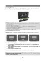
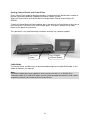
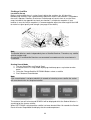
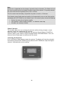
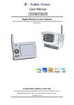
abc
MXL003
Seeker
Wireless
Installation & Operation
Instruction Manual
9111403 Iss 1
Useful Information
Date of Purchase
Retailer
Installer
Serial Number
2
Contents
Warranty ................................................................................................................................................................................ 4
Safety Precautions................................................................................................................................................................. 5
Introduction ............................................................................................................................................................................ 6
Proper Use & Operation .................................................................................................................................................... 6
Connections & Features ........................................................................................................................................................ 8
Control Panel .................................................................................................................................................................... 8
Control Box ....................................................................................................................................................................... 9
Antenna Unit ..................................................................................................................................................................... 9
Installation ........................................................................................................................................................................... 10
Required Tools & Equipment (not supplied) .................................................................................................................... 10
Product Contents ............................................................................................................................................................ 10
Selecting an Installation Location .................................................................................................................................... 11
Attaching Antenna Mount Plate & LNB Park Plate........................................................................................................... 12
Electrical Connections..................................................................................................................................................... 13
Attach Antenna Unit to Mounting Plate ............................................................................................................................ 15
Installing cables .............................................................................................................................................................. 15
Installing Control Box ...................................................................................................................................................... 16
Installing Control Panel ................................................................................................................................................... 18
Attach Satellite Dish to Antenna Unit ............................................................................................................................... 19
Testing Antenna Unit....................................................................................................................................................... 19
Operation Guide .................................................................................................................................................................. 20
Installing Batteries........................................................................................................................................................... 20
Time and Temperature Display ....................................................................................................................................... 20
Pairing Control Panel and Control Box ............................................................................................................................ 21
Cable Mode .................................................................................................................................................................... 21
Finding a Satellite ........................................................................................................................................................... 22
Pause Function ............................................................................................................................................................... 23
Lowering the Antenna ..................................................................................................................................................... 23
Ignition Mode .................................................................................................................................................................. 24
Connecting to a Satellite Receiver ....................................................................................................................................... 24
Power Consumption............................................................................................................................................................. 24
Skew Adjustment ................................................................................................................................................................. 25
Software Update .................................................................................................................................................................. 27
Preparing a USB Flash Memory Stick ............................................................................................................................. 27
Update Control Box Software .......................................................................................................................................... 27
Fault Finding ........................................................................................................................................................................ 28
Specification ........................................................................................................................................................................ 29
CE Declaration of Conformity............................................................................................................................................... 30
Information for Users on Collection and Disposal of Old Equipment and Used Batteries ...................................................... 30
Reception Maps ................................................................................................................................................................... 31
ASTRA 28.2E ................................................................................................................................................................. 31
ASTRA 19.2E ................................................................................................................................................................. 32
HOTBIRD 13.0E ............................................................................................................................................................. 32
ASTRA 23.5E ................................................................................................................................................................. 33
3
Warranty
Every new Ominsat Seeker Satellite System is thoroughly inspected and tested before
leaving the factory, and is covered by the following two years parts and workmanship
warranty from the date of original purchase.
Two years parts warranty. The customer is not responsible for the cost of replacement parts
if the original part is determined to be defective under the terms of warranty. The customer
is responsible for the cost of replacement parts after two years. This warranty does not cover
installation or external wiring.
Should any trouble develop during the warranty period please contact Maxview before the
warranty period expires. If you do experience a problem with the product contact Maxview
Customer Services on (01553) 811000 or email [email protected].
Please make sure you have the following ready when you call:
• Your name
• Address
• Telephone number
• Model number
• Serial Number
• Date of purchase
• Clear and concise details of the fault
• Details of who installed the product
The warranty does not apply where:
• The product has been abused, misused, improperly installed or improperly
maintained.
• The product has been installed without the use of Maxview mounting brackets
• Repairs have been made or attempted by a third party other then Maxview
• Repairs are required due to normal wear and tear
• Modifications have been made to the product
• The antenna unit, control box or control panel has been opened
• Damaged caused by abrasive cleaning or power washing
• Circumstances beyond the control of Maxview that have caused the product to no
longer operate correctly
• Customer is not the original owner or cannot provide proof of purchase
In no event shall Maxview be liable for any indirect, incidental, or consequential damages
from the sale or use of the product. This disclaimer applies both during and after the term of
the warranty.
This does not affect your statutory rights
4
Safety Precautions
Read this manual carefully and become familiar with your satellite antenna. Understand its
applications, its limitations and any hazards involved. Failure to follow all instructions listed
below may result in electric shock, fire and/or serious injury. Maxview declines all
responsibility in the event of incident or accident if they are due to a non observation of the
installation instructions or the way the product is used.
No modifications are permissible to the Antenna Unit, Control Box or Control Panel.
Installation
•
•
•
•
•
•
•
•
Installation should be carried out by a competent person.
Take care when working at heights keeping work area clean and tidy to avoid trip
hazards.
Use creeper boards where necessary to ensure roof construction can support your
weight.
Use a recommended adhesive from page 10 to bond the antenna unit to vehicle roof
and follow the manufacturer’s instructions during application.
Do not travel until adhesive has cured noting that curing times vary with weather
conditions
Power tools should be used in accordance with manufacturer’s instructions
All electrical work should be carried out by a competent person. If in doubt seek
advice from a qualified electrician.
The Control Box and Control Panel are for internal use only and are not waterproof.
Operation
•
•
•
•
•
•
•
•
•
•
Before starting your journey check that antenna is in the park position.
The maximum speed of vehicle with antenna mounted on roof is 81mph (130km/h).
Never operate the antenna if someone is in close proximity of the antenna.
Disconnect power to the antenna before installation or adjusting LNB skew angle.
If high winds or electrical storms are anticipated lower antenna to park position.
Maintain adequate ventilation around the Control Box to avoid overheating.
Do not allow children to operate the antenna unit.
Dispose batteries responsibly.
Remove Control Box fuse before accessing the roof space around the antenna unit.
Do not operate the Seeker Wireless with snow or ice on the antenna.
Servicing
•
•
•
•
•
•
•
•
•
If in the event that you do experience a problem with the system call Maxview
Customer Service +44 (0)1553 811000.
Any inspection or repair must be carried out by Maxview or an appointed
representative of the manufacturer.
No regular maintenance required on the system.
Do not remove cover on Antenna, Control Box or Control Panel.
Do not use solvent or abrasive cleaning agents on the system.
Use a soft damp cloth to clean the Control Box and Control Panel
Use a suitable mild detergent to clean the Antenna Unit.
Do not pressure wash the Antenna Unit.
Check the Antenna Unit fixings for mechanical integrity at least once a year
5
Introduction
Please read these instructions fully before using the antenna for the first time. The operation
of the antenna has been designed to be as simple as possible however should you require
any technical assistance please contact Maxview customer service on +44 (0)1553 811000
or visit www.maxview.co.uk.
Proper Use & Operation
The Seeker Wireless is designed to be installed in a motorhome, caravan or horsebox to
automatically locate a television broadcast satellite when the vehicle is stationary. The
system comprises of 3 main components.
1. The Antenna which is to be permanently mounted externally to the roof structure of a
motorhome/caravan/horsebox. The construction of the roof structure should be
suitably robust and have no protruding obstacles
2. The Control Box is designed to be mounted internally in a cupboard it controls the
antenna unit through a cable connection and is powered by 12v DC only.
3. The Control Panel is the user interface allowing commands to be sent to the Control
Box and the feedback to be displayed on an integral screen. It is designed for internal
use only. It communicates with the Control Box either by radio or cable connection.
Use of the equipment for any other purpose than the one specified is not permitted and will
invalidate the warranty.
All instructions and models are subject to change. In accordance with policy of progressive
product, the company reserve the right to alter specifications.
Copyright© these instructions are the sole property of Maxview Ltd and may not be
reproduced.
Please keep these instructions safe for future reference.
Recycle packaging where facilities exist.
6
Antenna
The Antenna is mounted to the
roof. It uses electric motors to
scan for satellite signals. It has 3
cable connections; 1 for
controlling the motors and 2
satellites signal cables from the
Twin LNB.
Control Box
The Control Box requires wired
connections for power, antenna
control and satellite signal. It can
be mounted discretely in a
cupboard and can be fixed
vertically and horizontally.
Control Panel
Wireless technology allows the
Seeker Control Panel to be
mounted in a convenient position
without unsightly wires. When not
in use the panel displays a 24
hour clock and internal ambient
temperature.
7
Connections & Features
Control Panel
4
1
5
2
6
3
7
8
10
11
9
1. Antenna Search button
2. Antenna Park button
3. Antenna position icon
4. Battery status icon
5. Change Satellite Up/Down buttons
6. Wireless mode icon
7. Cable mode icon
8. ON/OFF switch
9. Battery door
10. RJ25 Socket
11. Magnets
8
Control Box
4
1
5
2
6
3
7
10
8
11
12
9
1.
2.
3.
4.
5.
6.
Fuse
Power Switch
Power LED
Sync Button
Status LED
USB update port
7. LNB IN
8. LNB OUT
9. Antenna Connectors
10. RJ25 Panel Connector
11. Installation Button
12. Power input
Antenna Unit
1.
2.
3.
4.
1
Offset Antenna
Roof Mounting Plate
Twin LNB
LNB Park Plate
3
2
4
9
Installation
Required Tools & Equipment (not supplied)
•
•
•
•
•
•
•
•
•
•
•
•
•
25mm-38mm hole saw
2.5mm twist drill
Power Drill
No.2 Phillips screwdriver
Weather Resistant Elastic Adhesive* and Applicator gun
Surface Cleaner
10mm spanner
Hexagonal socket key 4mm
Deburrer/Round File/Emery paper
Conduit (recommend method for securing cables)
Automotive 2.5mm2 cable
Electrical connector block
F-F Fly lead ( for connection to satellite receiver)
*Maxview recommends the following adhesives:
• Sikaflex®-512 Caravan
• Geocel® Geobond HM
• Sikaflex®-252
Product Contents
•
•
•
•
•
Antenna Unit
Control Box
Control Panel
65/85cm Antenna (separate carton)
Accessory Pack
LNB Park Plate
Control Box bracket
Control Panel mount
RJ25 3m Cable
Battery 1.5v AA
Power Cable
No.10 Screws
No.6 Screws
Cable Clips
M6 Button Head Screw
M6 Locking Nut
6mm Plastic Washer
x1
x2
x1
x1
x2
x1
x6
x6
x 12
x4
x4
x4
10
Selecting an Installation Location
Positioning the Antenna Unit
• Check for obstructions such as roof lights and vents.
• Check for electrical cables beneath screw fixing points.
• Check Antenna Unit cables will reach Control Box (Maxview can supply extended
cables).
• Do not allow the dish to overhang the edge of the vehicle
• Clearance around antenna system when in use is shown with reference E
Direction of travel
A
B
C
D
E
E
65cm
100
17
49
67
110
85cm
117
17
49
85
125
A
D
B
C
Positioning Control Box
Site the Control Box in a convenient location where:
• Front and rear connections are accessible.
• Cables can be routed and concealed neatly.
• There is an electrical supply of 12v dc permanent and ignition.
• There is adequate ventilation.
• The Control Box is not encased with metal (if using wireless mode).
• Material construction and thickness is suitable for fixings.
Positioning Control Panel
The Control Panel is designed to be easily visible in the living area as it displays a clock and
thermometer when in sleep mode.
• Do not place near wet hazard areas such as near sinks or bathroom.
• Do not place near heat sources or in direct sunlight.
• Avoid placing Control Panel next to walk ways where it could easily be knocked.
11
Attaching Antenna Mount Plate & LNB Park Plate
1. Remove antenna unit from wooden transit packaging.
2. Remove mounting plate from Antenna Unit by removing 6 x M6 nuts using 10mm
spanner.
3. Clean roof, Mounting Plate and LNB Park Plate in accordance with adhesive
manufacturer’s guidelines.
4. Mark a centre line for the antenna making sure dish will not overhang vehicle.
5. Align notches on plate with centre line.
6. Mark the position of 6 screw fixing holes and centre hole.
7. Mark position of LNB Park Plate.
8. Drill 6 x 2.5mm pilot holes into the roof
9. Apply adhesive to entire surface of Antenna Mounting Plate and LNB Park Plate and
firmly place them into position.
10. Place a small amount of adhesive into each hole before screwing plate to roof.
11. Wipe off excess adhesive with a cloth.
Direction of travel
Centre Line
Antenna Mount Plate
LNB Park Plate
Note
•
•
•
•
Follow manufacturer’s instructions when applying adhesive. Do not travel until
adhesive has cured noting that curing times vary with weather conditions.
Take care when working at heights. Always follow ladder manufacturer’s safety
advice.
Use creeper boards where necessary to ensure roof construction can support your
weight.
Power tools should be used in accordance with manufacturer’s instructions.
12
Electrical Connections
Whilst the adhesive is curing prepare the electrical connections for the Control Box.
B
The
Control Box requires a permanent 12v supply and a secondary 12v supply that provides
power when the engine of the vehicle is running. Note: the brake
rake light circuit is not suitable.
It is recommended to create a new circuit direct to the battery using a minimum cable cross
sectional area of 2.5mm2 and an inline fuse of 5A.. Do not connect to existing circuits that
supply high power devices such as water pumps, air conditioning units or sources of
interference such
ch as electric igniters for gas stoves. Route cables carefully avoiding areas of
excessive heat such exhaust systems and any moving parts in the engine compartment or
drive shafts.
Power Cable Colours
Red
+12v
Green
Ignition (+12v)
Black
Negative Earth
arth
RED
GREEN
BLACK
Join Power Cable to new circuit using a robust connection method such as
• Crimp connectors
• Screw terminal connector block
• Snap fit automotive tap connectors
13
Caravans
Power can be taken directly from the leisure battery on the caravan. The ignition cable
should be connected to the ignition key circuit which can be traced using the charts below.
The caravan will either be fitted with the 13 Pin Euro Connector or have two 7/8 Pin
connectors.
13 Pin Euro Connector
Terminal
Number
1
2
3
4
5
6
7
8
9
10
11
12
13
Function
Left Hand Indicator
Rear fog light(s)
Earth for contacts 1 to 8
Right Hand Indicator
Right Hand Side lights, marker lights & number plate light.
Brake lights
Left Hand Side lights, marker lights & number plate light.
Reversing light(s)
Positive direct from battery (Power)
Positive ignition key on (Fridge)
Earth return for contact 10
Signalling connection to trailer
Earth return for contact 9
13 Core Wire
Colour
Yellow
Blue
White
Green
Brown
Red
Black
Pink
Orange
Grey
White/Black
White/Blue
White/Red
12S 7 Pin Connector
Terminal
Number
1
2
3
4
5
6
7
Function
Reversing light(s)
Positive ignition key on (Battery Charging)
Earth
Positive direct from battery (Power)
Reverse Sensor (Optional)
Positive ignition key on (Fridge)
Earth return for contact 6
13 Core Wire
Colour
Yellow
Blue
White
Green
Brown
Red
Black
Caution
All electrical work should be carried out by a competent person. If in doubt seek advice from
a qualified electrician.
14
Attach Antenna Unit to Mounting Plate
Carefully lower the antenna unit onto the Mounting Plate and re-attach the M6 Nuts and
Washers that were previously removed.
Caution
Replace Nylon locking nuts if they have been removed more than twice. The locking action
of the Nylon becomes less effective if repeatedly assembled and disassembled.
Installing cables
1. Check there are no hidden cables in the roof structure and that the hole location is
clear of obstructions both internally and externally.
2. Using a holesaw drill a 25mm – 38mm hole to pass the antenna cable and satellite
cables.
3. Clean off any burrs from the hole and clean surface.
4. Pass cables through the hole.
5. Using adhesive bond cable entry plate to the roof – note the 3 cable glands should
face the rear of the vehicle.
6. Secure cable to roof using the cable clips (supplied).
Note
To prevent trip hazards it is recommended that cables are concealed in PVCu conduit (not
supplied) where access is required to the roof of the vehicle.
15
Installing Control Box
Having previously chosen a suitable location
1. Clip the mounting brackets onto the Control Box.
2. Place Control Box on the horizontal or vertical surface and mark the 4 holes.
3. Depending on material drill a pilot hole or use a bradawl.
4. Attach cables to Control Box refer to page 9 for details.
5. Screw control box into position using 4 x No. 6 Screws.
Mounting Positions
Position the Control Box in one of the 4 ways shown below. Make sure that the front is easily
accessible.
Fitting the Control Box Brackets
The brackets snap fit to the Control Box casing
16
Connection Diagram
Antenna Cable
Satellite Cable
TV
&
Satellite
Receiver
Satellite Cable for PVR or
additional Satellite Receiver
Satellite Cable
Optional Cable
for Control
Panel
IGNITION
5A FUSE
17
Installing Control Panel
Choose most suitable method of communication between Control Panel and Control Box.
Wireless Mode
1. Install batteries into Control Panel in accordance with instructions on page 20.
2. Turn Control Box and Control Panel on.
3. Pair Control Box and Panel together see page 21.
4. Choose suitable location for Control Panel – press change sat button
periodically to check wireless reception.
5. When satisfied with the location of the Control Panel mark the position of the
fixing holes on the magnetic mount then attach to wall with 2 No.6 screws.
Knock-outs
for vertical
cable routing
Cable Mode
1. Choose a location to mount the Control Panel.
2. Mark the fixing holes then make a pilot hole with a drill or bradawl.
3. If required remove one of the knock outs with a pair of pliers
4. Pass cable through hole in Magnetic Mount.
5. Screw the Magnetic mount to the wall with the RJ25 cable laying flat and un-twisted
in the channel.
6. Connect the Control Panel to the RJ25 cable and place onto Magnetic Mount whilst
pulling through the cable.
18
Attach Satellite Dish to Antenna Unit
1. Ensure Antenna Unit is free from obstacles.
2. Press installation button on reverse of Control Box to elevate antenna. Once elevated
turn off power to Control Box and remove fuse.
3. Fix satellite dish to Antenna Arm using M6 Button Head Screws, M6 Nuts and 6mm
Plastic Washers. The 65cm and 85cm satellite dishes have different fixing hole
positions. Therefore 4 of the holes will be unused.
4. Remove all tools, packaging and obstructions from roof.
5. Replace fuse and turn power switch on. Antenna will automatically retract into the
park position.
Caution
Replace Nylon locking nuts if they have been removed more than twice. The locking action
of the Nylon becomes less effective if repeatedly assembled and disassembled.
Testing Antenna Unit
Position the vehicle so that there is an unobstructed view of the southern sky. Connect a TV
and Satellite Receiver and follow instructions on page 22 to search for a satellite.
Caution
Before driving vehicle on a highway ensure adhesive has cured.
Check all fasteners are secure.
19
Operation Guide
Installing Batteries
Remove the battery door and insert 2 AA (LR6) batteries as shown. Take care to observe
the correct polarity and to use good quality sealed alkaline batteries.
Caution
• Incorrect installation may cause battery leakage and corrosion, resulting in damage to
the Control Panel.
• Do not mix old and new batteries.
• Do not mix different battery types (such as alkaline and manganese batteries).
• Do not use rechargeable (Ni-Cd) batteries.
• Do not burn or breakup batteries.
• Batteries must not be exposed to excessive heat such as direct sunlight or fire.
Time and Temperature Display
The Control Panel will automatically display the ambient temperature when the antenna is
not in use.
To enable the clock function:
1. Press and hold Satellite UP and Down buttons for 3 seconds
2. The clock will be shown with the Hour digits flashing. Press Up or Down buttons to
adjust the hours.
3. Press the Satellite Search button to select the minutes. Press Up or Down buttons to
adjust minutes.
4. Press Antenna Park button to Exit.
The clock will be displayed when the panel has been inactive for 10 seconds.
Note
The clock requires power from the batteries. Turning the panel off via the switch or changing
the batteries will disable the clock function.
The clock is 24 hour display only.
20
Pairing Control Panel and Control Box
Every Control Panel made by Maxview contains a unique electronic identification number to
prevent interference between neighbouring Seeker satellite systems.
When the Control Panel and Control Box are not paired the Control Panel displays RF
ERROR.
To pair the Control Box and Panel together press and release the Sync Button on the front of
the Control Box. The Status LED will illuminate green. Then press Satellite UP or Down
button on the panel to synchronise.
This operation is only required during installation and after any software updates.
Press Sync
Button
Press Satellite
UP/Down Button
Cable Mode
The Control Panel and Box can also be connected through the included RJ25 cable. In this
mode no batteries are required.
Note
If a different cable to the one supplied is to be used ensure that it is an RJ25 6 Pin 6
Connector cable. RJ11 and RJ14 cables use the same connector but contain 2 and 4 wires
respectively and will not function with the Control Panel.
21
Finding a Satellite
Location & Set-up
Before starting check there is a clear line of sight to the southern sky. All television
broadcasting satellites have a geostationary orbit which means their location is fixed above
the earth’s equator. Satellites also have a limited range of transmission so use the Zone
maps included in the appendix to check your location is suitable for reception. If your
location is near the limit of reception it is recommended to adjust the skew angle of the LNB
to maximise signal quality and strength (see page 25 for details)
Note
The Seeker Wireless works independently from a Satellite Receiver. Therefore, any satellite
receiver can be used.
Ensure the TV and Satellite Receiver are connected in accordance to the manufacturer’s
instructions.
Starting Search Mode
1. Turn on Control Box and Control Panel
2. If Control Panel is in sleep mode displaying clock/temp press any button to wake
panel
3. Using the Change Satellite UP/DOWN Buttons select a satellite
4. Press Antenna Search button
Note
If the search button is not pressed within 3 seconds of selecting a new satellite the seeker
will revert back to the last acquired satellite.
The antenna icon will animate and SEARCH will be displayed whilst the Seeker Wireless is
searching for the chosen satellite.
When SAT FOUND is displayed the satellite has been located. After 10 seconds the Control
Panel will enter Sleep Mode and display the time and temperature.
22
Note:
Search time is dependent on the change in elevation from last location. The Seeker will start
the search routine from the last known elevation angle of the antenna. This greatly reduces
the search time which will typically be less than 1 minute.
The first search from the factory set position may take as much as 15 minutes.
If the Seeker cannot find the desired satellite it will automatically return to the Park position
and display NO SAT FOUND on the Control Panel. If this occurs please check the following:
•
•
•
Antenna has clear line of sight to satellite
Your location is within range of satellite – as shown on zone map
All cables are correctly installed
Pause Function
This function allows the user to change the desired satellite mid-way through a search
operation without the need to lower the antenna.
Whilst the seeker is in SEARCH mode press the Antenna Search Button to PAUSE the
antenna. Select a new satellite using the Change Satellite UP/DOWN Buttons. Press the
Antenna Search Button again to continue with the search.
Lowering the Antenna
Press the Antenna Down button to lower the antenna. The display will show the animated
icon lowering and text ANT DOWN flashing. When the ANT DOWN text stops flashing the
antenna is lowered and safe for travelling.
23
Ignition Mode
The ignition mode is a safety feature that automatically lowers the antenna and prevents
accidental operation whilst travelling.
When the Seeker has detected an active ignition circuit in the vehicle the Control Panel will
display ‘IGNITION’. In this mode the antenna is automatically lowered and the Control Panel
function is disabled.
Note
The Control Box must be wired to a 12v DC electrical circuit that is live when the vehicle’s
ignition is on. This not only provides a safety benefit but also refreshes the Control Box
memory which allows the Seeker Wireless to perform correctly.
Connecting to a Satellite Receiver
The Seeker Wireless satellite system features a twin LNB for connection to a PVR or 2
separate receivers. One of the satellite cables must connect to the Control Box. The Control
Box will then output this signal through the F connector marked ‘RECEIVER’.
In order for the satellite signal to pass through the Control Box the power must be on.
Power Consumption
The Seeker Wireless has been designed to minimise power consumption.
When not in use the system enters a sleep mode where wireless communication between
the Control Panel and Box is suspended. This is where time and temperature are displayed
on the Control Panel.
When the Seeker is not used for long periods of time it is recommended to switch off the
Control Panel and Box. The Ignition Mode will still activate even with the Control Box power
switch in the off position.
When power is restored to the system the antenna will automatically lower into the park
position.
24
Skew Adjustment
Skew adjustment is required when signal strength is weak at the limit of a given satellites’
reception area. It involves adjusting the angle of the LNB on the roof mounted antenna unit.
-
+
ASTRA 28.2
25
ASTRA 19.2
Caution
Follow general safety advice on page 5 when adjusting Antenna Unit.
26
Software Update
To keep your Seeker up to date with the latest satellites Maxview has incorporated a USB
port on the front of the Control Box. The Seeker has the ability to update its satellite data and
its operational software from a simple USB flash memory stick.
Please visit www.maxview.co.uk for latest software and a guide to installation.
Preparing a USB Flash Memory Stick
Use a blank USB flash memory stick formatted to FAT or FAT32
Format USB stick:
In Windows XP, Vista or Windows 7
Insert USB key in PC, find device in ‘My Computer’, right click and select ‘Format...’
Select options as shown below press start.
Update Control Box Software
1. Obtain a update-xxxx.hex file from Maxview and copy onto a formatted USB flash
memory stick.
2. Turn on Control Box.
3. Press and hold the SYNC button on the front of the Control Box for 7 seconds until
SYNC LED illuminates RED.
4. Insert the USB flash memory stick. The SYNC LED will flash GREEN whilst data is
been transferred.
5. When the SYNC LED goes out turn off the Control Box power and remove the USB
flash memory stick.
6. Turn power on, SYNC LED will flash RED and GREEN whilst data is written to
Control Box memory.
7. When SYNC LED goes out update is complete.
8. Pair Control Panel to Control Box (see page 21)
Note
If Status LED does not flash RED and GREEN when power is restored after update then the
software has not been loaded successfully. Check the readme file created by the Control
Box on the USB flash memory stick for details. An update will not be successful if the file to
be loaded is the same as the one already stored in the Control Box.
If you experience difficulties please contact Maxview customer service.
27
Fault Finding
Problem
RF ERROR
Control Panel
AZ ERROR
EL ERROR
NO SAT FOUND
IGNITION
No clock displayed
Control Panel screen
blank
Antenna
Control Box
Lost Control Panel
Pressing buttons gives
no response
No power
Fuse blows repeatedly
USB update failed
Antenna stuck in
elevated position
Actions
Move Control Panel closer to Control Box.
Check Control Box power is on.
Panel and box are not paired (see page 21).
Movement of motor not detected therefore check cable
connections and reset power.
If problem is not resolved contact Maxview customer
service.
Check antenna has no obstructions to the southern sky
Check LNB cable connection
Weak signal area – adjust skew angle (see page 25)
Software update required (see page 27)
Safety feature to prevent antenna operating whilst engine is
running. Turn off vehicle ignition before operating antenna.
Battery power has been interrupted. Reset clock (see page
20)
Batteries exhausted. Replace batteries (see page 20) or
use cable connection
Check Control Panel power switch is on
Contact your local dealer or Maxview customer service
Reset power to Control Panel and Control Box
Check Fuse
Check Power cable connection
Leisure battery voltage is low
Check Fuse rating is 3A
Check antenna unit is not obstructed
Contact Maxview Customer Service
Check file was added to a blank FAT formatted USB
memory stick
After update check text file added to USB memory stick
Contact Maxview Customer Service
DO NOT TRAVEL UNITIL ANTENNA UNIT IS REMOVED
Remove antenna unit from roof by releasing 6 x M6 Nuts.
Carefully lift and place antenna unit on its side so that the
underneath is accessible. Remove plastic connector covers
with a pozi no2 screwdriver. Disconnect cables so that
antenna unit can be removed from roof. Make sure cables
are secured to roof before travelling.
28
Specification
Antenna Gain
LNB Outputs
Wireless Frequency
Wireless range
Battery type
Fuse
Dimensions
Antenna Height (min)
Antenna Height (max)
Control Panel (H x W D)
Control Box (H x W D)
Mass
Antenna
Control Panel
Control Box
Power Consumption
Searching
Standby
Supply Voltage
Elevation Angle Range
Azimuth Rotation Angle
Search time
Skew Angle
Note
•
•
MXL003/65
36.0dB
MXL003/85
38.1dB
2
868.3 MHz
10 m
2 x AA LR6 Alkaline Sealed
3A Mini Blade Automotive
167mm
167mm
960mm
1130mm
80mm x 120mm x 25mm
40mm x 200mm x 140mm
10kg
11kg
140g
400g
2W
24W
0.5W
9.5v – 14.5v
10°-70°
380°
30s - 15min
±45°
Design and Specifications are subject to change without notice.
Mass and Dimensions shown are approximate.
29
CE Declaration of Conformity
The Seeker Wireless Satellite Antenna has been designed, constructed and marketed in
compliance with safety requirements of EEC Directive 2006/95/EEC (Low voltage) and
requirements of EMC Directive 2004/108/EEC.
The wireless operation has been designed in accordance with CEPT-70.03.
Company Address:
Maxview Ltd
Common Lane
Setchey
Kings Lynn
Norfolk
PE33 0AT
England
Information for Users on Collection and Disposal of Old Equipment and
Used Batteries
These symbols on the products, packaging, and/or accompanying
documents mean that used electrical and electronic products and
batteries should not be mixed with general household waste. For
proper treatment, recovery and recycling of old products and used
batteries, please take them to applicable collection points, in
accordance with your national legislation and the Directives
2002/96/EC and 2006/66/EC.
By disposing of these products and batteries correctly, you will help
to save valuable resources and prevent any potential negative effects
on human health and the environment which could otherwise arise
from inappropriate waste handling.
For more information about collection and recycling of old products
and batteries, please contact your local authority, your waste disposal
service or the point of sale where you purchased the items.
Penalties may be applicable for incorrect disposal of this waste, in
accordance with national legislation.
For business users in the European Union
If you wish to discard electrical and electronic equipment, please
contact your dealer or supplier for further information.
[Information on Disposal in other Countries outside the
European Union]
These symbols are only valid in the European Union. If you wish to
discard these items, please contact your local authority or dealer and
ask for the correct method of disposal.
Note for the battery symbol (bottom two symbol examples):
This symbol might be used in combination with a chemical symbol. In
this case it complies with the requirement set by the Directive for the
chemical involved.
30
Reception Maps
ASTRA 28.2E
2A/B North Beam
2A/B South Beam
ASTRA 2D
31
ASTRA 19.2E
1KR 1L & 1M
1H
HOTBIRD 13.0E
32
ASTRA 23.5E
3A
3B
33
34