1
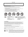
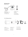
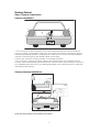
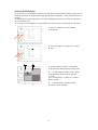
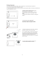
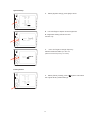
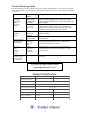
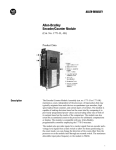
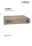
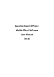
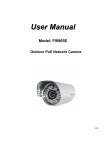
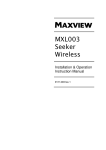
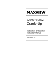
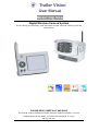
User Manual
Model: Digi-View
Digital Wireless Camera System
This is a driving aid, safe driving, good observation and use of the rear-view/wing mirror are
still necessary.
PLEASE READ CAREFULLY AND SAVE
This manual contains important information about this product's operation. If you are
installing this product for others, you must leave this manual, or a copy,
with the end user.
1
Digi-View
Index
System Components
Safety Precaution and Hazard Notice / FCC Warning / Disposal
System Parts
Getting Started
Step1: System Connection
Step2: Basic Operation
Monitor Function Buttons and Display Indications
View Mode
Step3: Advanced Operation
The Menu
Setting Auto / Manual Scan Sequence
Setting QUAD Display
Pairing a Camera
System Setup and Reset
Trouble Shooting
Trouble Shooting Table
Product Specification
System Components
(1) Digital Wireless IP65 Colour Camera
(1) Digital Wireless 3.5" LCD Monitor
(1) Antenna for the camera
(1) 5V Cigarette-Lighter Power Adapter for the Monitor
(1) Windscreen mount for the Monitor
(1) Dash-board mount for the Monitor
(1) Screw/fixings bag
(1) User Manual
2
WELCOME
Dear Customer,
Thank you for purchasing this unique product, which utilises the latest digital wireless technology ensuring ZERO interference.
Please read the following information carefully before installing and using this product.
Important Safety Precautions
Damage caused by non-compliance with this operating manual will void the warranty! We will not assume any liability
for damages to items or persons caused by improper handing or
non-compliance with the safety notices! Any warranty claim will be null and void in such cases.
1.
2.
3.
4.
5.
6.
7.
8.
9.
Do not drop, puncture or disassemble the camera or monitor; otherwise the warranty will be void.
Never tug on the power cords.
Do not expose the monitor to high temperature or leave it positioned in direct sunlight (e.g. permanently fixed to
the windscreen). Doing so may cause damage or temporary malfunction.
Use the system with care, only gentle pressure is required to operate the monitor buttons.
For your own safety, avoid using the camera or power off, when there is a storm or lightning.
Remove the monitor power adapter during long periods between use.
Use only the accessories and power adapters supplied by the manufacturer.
To meet the regulations pertaining to parental responsibility, keep the devices out of the reach of infants.
Ensure that power cables, do not get crushed or damaged by sharp edges.
FCC Compliance Statement:
This device complies with Part 15 of the FCC
Rules. Operation is subjected to the following
two conditions:
(1) this device may not cause harmful
interference, and
(2) this device must accept any interference
received, including interference that may
cause undesired operation.
Products with CE Marking comply with EMC
Directive (2004/108/EC); Low Voltage Directive
(73/23/EEC); R&TTE(1999/5/EC) issued by the
Commission of the European Community.
Compliance with these directives implies conformity
to the following European Norms:
EMC: EN 301 489
LVD: EN 60950
Radio: EN 300 328
FCC/CE WARNING
This equipment has been tested and found to comply with limits for a Class B digital device, pursuant to Part 15 of the
FCC rules and ETSI(EN) 300328 .These limits are designed to provide reasonable protection against harmful
interference in residential installation. This equipment generates, uses, and can radiate radio frequency energy, and if
not installed and used in accordance with the instructions, may cause harmful interference to radio communications.
However, there is no guarantee that interference will not occur in a particular installation. If this equipment does cause
interference to radio or television equipment reception, which can be determined by turning the equipment off and on,
the user is encouraged to try to correct the interference by one or more of the following measures:
- Reorient or relocate the receiving antenna.
- Move the equipment away from the receiver.
- Plug the equipment into an outlet on a circuit different from that to which the receiver is connected.
- Consult the dealer or an experienced radio/television technician for additional suggestions.
You are cautioned that any change or modifications to the equipment not expressly approved by the party responsible
for compliance could void your authority to operate such equipment.
Disposal
If the camera system no longer functions or can no longer be repaired, it must be disposed of according to the valid statutory
regulation for disposal of spent batteries / such equipment.
You are required by law (Battery Ordinance) to return all spent batteries and accumulators. Disposing
of spent batteries/accumulators with common household waste is prohibited! Batteries/accumulators
that contain hazardous substances are marked with the symbols on the side. These symbols indicate
that it is prohibited to dispose of these batteries/accumulators in household waste. The abbreviations
for the respective heavy metals are: Cd = cadmium, Hg = mercury, Pb = lead. You can return spent
batteries and accumulators that can no longer be charged to the designated collection points in your
community, outlets or wherever batteries or accumulators are sold. Following these instructions will
allow you to fulfill the legal requirements and contribute to the protection of our environment!
3
The System Parts
Wireless Camera
6
1. Camera Lens
5. EDS (light sensor)
2. Pairing key (under cover)
6. Antenna
3. Mounting Bracket
7. Power Cable
4. IR LED (Night Vision)
8. Pair LED Indicator
9. Power LED Indicator
3.5" LCD Wireless Receiver
9
12
13
1. Antenna
6. Resolution Switch
11. DC Input Socket
2. Pair LED Indicator
7. LCD Screen
12. Cigarette Adaptor
3. Power LED Indicator
8. Monitor Stand
13. Windscreen Mount
4. Control Panel
9. Reset Button
14. Dash-board Mount
5. Camera Select / Pair
10. Power Button
4
14
Getting Started
Step1: System Connections
Camera Installation:
1. For reversing, choose a location on the rear bumper etc that you wish to install t h e
c a m e r a (usually in the middle of bumper), for a HGV, motor-home, caravan etc high up
and looking down/backwards, usually gives the best view. For inside a horsebox/trailer,
mount the camera high up and ideally behind the horse(s).
2. Screw the camera's mounting bracket to the desired location.
3. For reversing, connect the power cable to the reversing light of the vehicle and the
camera will be automatically powered when the vehicle is in reverse; otherwise connect to
any available power source e.g. the side-lights (ideally use a switched source to prevent
inadvertent battery drain).
Camera Antenna Installation:
Screw the dipole antenna to the antenna connector.
5
LCD Monitor Installation:
1. Remove the protection film from the LCD monitor.
2. Secure the windscreen holder to the back of the monitor with the 4 screws provided.
3. Attach the rubber pad to the windshield. Make sure the glass is clean and dry to ensure that
the holder fixes securely.
4. Pull the lock knob down to fix the holder (this mount is not designed to be left permanently in
the windscreen – please use the dashboard mount for permanent fixture).
4. Connect the cigarette lighter power adaptor to the DC power jack of the LCD monitor.
ONLY use the provided power adaptor (a hard-wire power adapter is available separately).
5. Plug the cigarette lighter power adapter into the vehicles cigarette lighter socket (which may
operate via the ignition).
6. Position the monitor antenna (& camera antenna) vertically to achieve the best reception.
6
Step 2: Basic Operation
Monitor Function Buttons and Indicators
1. [Power Button]
Press button to power ON; hold it for 2 seconds to power OFF the monitor.
2. [Pair indicator]
Illuminated when the system is operating properly; blinking when the system is pairing with a
new camera.
3. [Power Indicator]
LED comes ON when the Monitor is powered ON.
▲ LED remains ON while monitor is OFF in [Power Save] Mode.
4. (Menu Mode) [Cursor UP] / (QUAD Mode) [Hot key CH1]
5. (Menu Mode) [Cursor DOWN] / (QUAD View Mode) [Hot key CH2]
6. (Menu Mode) [Cursor Right / Vol+] / (QUAD View Mode) [Hot key CH3]
7. (Menu Mode) [Cursor Right / Vol-] / (QUAD View Mode) [Hot key CH4]
8. (Menu Mode) [Menu / Enter Button]
9. (View Mode) [Scan Channels] / (Menu Mode) [Pair Camera]
In View mode, manually scan the available camera channels.
In Pair mode, assign and pair a camera to a specific channel.
10. (View Mode) [Resolution Switch]
Switch between VGA and QVGA resolution.
▲ It is recommended to set the resolution to QVGA. See [Basic Operation - In the View Mode]
section as a guide.
11. [Reset Switch]
Press with a pin/small object to reset and restore system hardware status.
Press the switch ONLY if the system has crashed and there is no response from any of the
buttons.
7
In View Mode
1.
Signal Indicator
2.
Channel Indicator
3.
Resolution Indicator
1.
Status Indicator
A. Signal Indicator shows signal strength, more bars indicate a stronger signal.
Signal Level
Indicator
VGA Frame Rate
QVGA Frame Rate
Perfect
5~10Fps
15~30Fps
Good
3~5Fps
12~20Fps
Fair
2~4Fps
8~15Fps
Low
0~1Fps
0~4Fps
Zero
0Fps
0Fps
It is recommended to set the resolution to QVGA. To do so, simply press the [Resolution]
button to switch to QVGA as shown on the [Resolution Indicator].
▲
B. Reversing Camera Operation Steps:
1. Press [Power] button to switch ON.
2. Switch to QVGA mode if necessary.
3. Select reverse gear (if the camera is powered by the reversing light).
4. Reverse image will be displayed.
5. If the/a camera is used to view the interior of a vehicle/horsebox/trailer, or behind a
caravan/motor-home, then it should be powered from an ignition controlled circuit, or a lighting
circuit could also be used.
▲ STOP REVERSING when [NO Signal] shows on the monitor.
▲ Press [Cam] button to locate the reversing camera channel if necessary.
▲ This is a driving aid; safe driving, good observation and use of the rearview/wing mirror
are still necessary.
8
Note: The Channel indicator shows the current camera viewed by the monitor, by pressing the
‘Cam’ button, you can manually switch between different cameras (see below).
9
Step3: Advanced Operation
Knowing the Menu:
By Pressing OK (Menu), you can enter / exit Menu Mode
You can Use Left / Right / Up / Down to select and change the settings.
Resolution
QUAD
CAM1
QVGA
OFF
ON
CAM2
OFF
CAM3
OFF
CAM4
OFF
Pair CAM
1234
System Setup
Factory Reset
Setting The Resolution:
You can use Left / Right to change Resolution between VGA and QVGA
Resolution
QUAD
LINK
QVGA
OFF
CAM1
OK
ON
CAM2
OFF
CAM3
OFF
CAM4
OFF
Pair CAM
1234
System Setup
Factory Reset
1
0
Setting Auto / Manual Scan Sequence:
This function is available for multi-camera use
▲
▲ QUAD will be turned off every time you press
Resolution
QUAD
CAM1
LIN K
OK
CAM3
CAM4
Pair CAM
QVGA
OFF
ON CAM2
OFF
OFF
OFF
1234
Systern Setup
Factory Reset
(Cam) for manual scan
A. Use Left / Right to change QUAD to OFF.
B. Press
10
to manual scan.
Setting QUAD Display
▲ This function is available for multi-camera use. Before setting QUAD display, make sure all
cameras are paired to assigned channels. See [Advance Operation – Pair Camera] section as
a guide.
▲ QUAD display will be restored to one camera display every time you press the directional
keys for manual scan.
▲ To ensure correct display, turn all available channels ON prior to selecting QUAD mode.
Resolution
LI N K
OK
QUAD
OFF
CAM 1
ON
CAM 2
CAM 3
OFF
OFF
CAM 4
Pair CAM
System
Factory
Resolution
QUAD
CAM 1
LI N K
CAM 2
CAM 3
CAM 4
Pair CAM
OK
Systern
Factory
CH1
QVG A
A. Use Left / Right to turn all available
channels ON.
OFF
1234
Setup
Res et
QVG A
ON
ON
B. Use Left / Right to change Scan Time to
QUAD.
ON
ON
ON
1234
Set up
Res et
CH2
C. QUAD display as shown. Unavailable
channel will be displayed as a blank screen.
To leave QUAD display, simply press
Left/ Right /Up / Down to go to specific
channel.
Left = CAM4; Right = CAM3; Up = CAM 1;
Down= CAM2.
LI N K
▲
OK
CH3
CH4
▲ In QUAD display [ZOOM] / [Pair]
functions are not available.
11
Pairing Camera(s)
▲ Proceed with this function ONLY when a camera can not be found by the system or
when you have additional/new camera(s) to pair.
▲ Before pairing the camera, make sure that the camera power cable is correctly connected to the
reversing light/power source.
A. Simply pair the camera by selecting the
desired channel in Menu Mode.
B. Only assign one camera to one channel.
Channel memory will be overwritten if used
again.
C. Pairing new camera to channel 3, settings as
shown:
D. Press (Pair) button (NOT ‘OK’).
E. System will begin count down, within
60 seconds, system message as shown:
F. Within the 60-second count down, press the
Pair Key, located on the camera cable.
▲ To compete Pairing, select reverse gear (if
the camera is powered by the reversing light,
otherwise ensure that the camera is powered),
have the hand brake ON then press the
camera Pair button (with ignition on, but engine
NOT running).
G. Once pairing completed, camera and
receiver status indicators as shown.
12
System Setup
A.
L IN K
OK
Select [System Setup], press [OK] to enter.
Resolution VGA
QUAD OFF
CAM1
ON
CAM2
OFF
CAM3
OFF
CAM4
OFF
Pair CAM
1234
System Setup
Factory Reset
B. Use Left /Right to adjust monitor brightness.
L IN K
OK
0
Brightness
8
Frequency 50Hz
15
▲ Brightness setting effects the LCD
monitor only.
C. Use Left / Right to change frequency
between 50Hz and 60Hz (for the UK,
please set the frequency to 50Hz).
L IN K
OK
Brightness
50
Frequency Hz
Factory Reset
Resolution
QUAD
CAM1
CAM2
L IN K
OK
VGA
OFF
ON
OFF
A. Select [Factory Reset], press [
the original factory default settings.
CAM3
OFF
CAM4
OFF
Pair CAM
1234
System Setup
Factory Reset
13
] ,System will restore
Trouble Shooting
This section offers some helpful information to overcome most of the problems that you may
encounter. We also hope that this section assists you to achieve a quick and easy
installation/setup.
Problem Diagnosis
This innovative digital wireless solution integrates advance Frequency Hopping Spread
Spectrum (FHSS) technology. This technology greatly reduces the interference that comes
from other devices using the same radio frequency (2.4GHz), e.g. WIFI, Bluetooth, cordless
phones etc. You can now enjoy superior wireless picture quality without a flickering or noisy
image. However, weaker signal (lag or still image) may be observed from time to time,
depending on the environment where the system is installed.
The system complies with FCC part 15.247, ETSI (EN) 300 328, audio/video signals transmitted
about, or over 500 feet / 150 metre in the ‘line of sight’. However, ‘line of sight’ installation is
difficult to achieve due to obstacles etc. Factors affecting transmission include microwave ovens
and/or other high frequency electromagnetic waves. Reinforced concrete walls, large-scale metal
products and objects should not be located near to the camera, or the monitor. Water also
creates an obstacle to signal transmission, as it absorbs the signal and should be avoided.
People etc passing through the transmission area may also cause unstable signal quality.
However, in ‘normal use’ as a rear-view or interior (vehicle) camera, the system should offer
excellent performance and provide a clear and interference-free image/view.
How to improve the wireless signal quality?
If possible, remove any obstacles from between the camera and monitor that might reflect/absorb
the signal. Obstacles could include furniture, cabinets or walls. If the wireless signal strength is
low, position the monitor/antenna at a new angle (ideally vertically), or readjust camera/monitor
position until an improvement is achieved. Or, if possible, relocate the camera closer to the
monitor.
Why Image Compression?
In order to achieve a secure and interference free signal, this digital wireless system utilises a
narrow 2Mb frequency-hopping bandwidth. Different from traditional 2.4GHz analogue wireless
systems, the digital wireless signal is compressed and then transmitted in Motion JPEG (MJPEG)
format. By digitising and compressing the raw analogue data the available bandwidth is used
more efficiently/securely. Consequentially, you might observe an indent image line if you are
using a larger display monitor, or a plasma TV.
How to improve the image quality when using large display screens?
When QVGA is selected, ‘pixel scattering’ is unavoidable. However, you can change the image
to VGA and by doing so, more pixels are ‘scattered’ on the screen. Therefore to achieve the best
display performance, when outputting the video/signal, a 32" or smaller monitor / TV is
recommended.
14
Trouble Shooting Table
Before requesting service, please refer to the checks detailed below. If you are in any doubt
about the following, or if the solutions described in the table do not solve the problem, please
contact us.
Problem
System
Message
shows “NO
Signal ”
on monitor
screen
Low signal or
unstable
signal
Camera image is
missing during
manual scan
Dim / over
bright
image on
monitor
screen
Image frozen
and the monitor
function buttons
don’t respond
Possible
Cause
No power
supply to the
corresponding
camera(s)
Remedy
Channel is not
paired with
the camera
To complete Pairing, ensure that the camera is
powered, select camera to ‘Pair’ via the monitor menu
then press the camera pairing button. See [Advanced
Operation - Pairing Camera] section as a guide.
Antenna
directional
limitation
Strong radio
signal nearby
Scan
channel(s)
been set
OFF
Adjust & secure camera antenna, position camera & monitor
antenna vertically.
Monitor
brightness
adjusted
incorrectly.
Press [OK] button, go to menu, enter [System Setup];
adjust [Brightness]. See [Advance Operation – System
Setup] for detail.
System crash
Use a pin/small object to press [Reset Switch] to restore
the system.
Check that the reversing light (if the camera is powered
from the reversing light) is working. Check the camera
wiring, ensure the polarities are correctly connected and 1224V is available.
Relocate source of the radio signal, or reposition the
camera/monitor.
Press [OK] button, go to the menu and enable the
channel(s). See [Advance Operation – Setting Auto /
Manual Scan Sequence] for detail.
For technical support please email:
[email protected]
PRODUCT SPECIFICATION
Maximum Channels
Camera
Monitor
1
4
Communication Range
200 metres in open space
Resolution
640 × 480 (VGA)
Operating Temperature
-10˚C + 50˚C
C
DC 5V
Operating Voltage
DC 12V~24V
Current Consumption
160mA (max)
Night View Range
3~5M
Dimension
95 × 92 × 80mm
850mA (max)
15
233 × 145 × 36mm