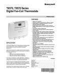
1
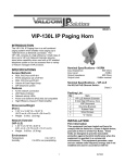
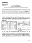
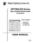
Bose® FreeSpace® 4400 System User Interfaces
Operating Guide
®
FreeSpace 4400 System AVM 1-Zone User Interface
FreeSpace® 4400 System AVM 2-Zone User Interface
FreeSpace® 4400 System Page User Interface
Important Safety Instructions
For the intended audience
This guide has been written for professional installers of sound systems.
1.
2.
3.
4.
5.
6.
7.
8.
9.
10.
11.
Read these instructions – for all components before using this product.
Keep these instructions – for future reference.
Heed all warnings – on the product and in the installer’s guide.
Follow all instructions.
Do not use this apparatus near water or moisture.
Clean only with a dry cloth – and as directed by Bose.
Do not block any ventilation openings. Install in accordance with the manufacturer’s
instructions.
Do not install near any heat sources, such as radiators, heat registers, stoves, or other
apparatus (including amplifiers) that produce heat.
Refer all servicing to qualified service personnel. Servicing is required when the apparatus
has been damaged in any way such as: liquid has been spilled or objects have fallen into the
apparatus; the apparatus has been exposed to rain or moisture, does not operate normally, or
has been dropped. Do not attempt to service this product yourself. Opening or removing covers
may expose you to hazards. Please call Bose to be referred to an authorized service center near
you.
See product enclosure for safety-related markings.
Only use attachments/accessories specified by the manufacturer.
CAUTION: Check local regulations before installing the Bose® FreeSpace® 4400 System AVM 1-Zone User
Interface, FreeSpace® 4400 System AVM 2-Zone User Interface, and/or FreeSpace® 4400 System Page User
Interface. The building code may require professional installation by a skilled technician or licensed contractor.
Regional electrical codes may require similar qualifications for wiring the system.
Please read this install guide
The Bose FreeSpace® 4400 System AVM 1-Zone User Interface, FreeSpace® 4400 System AVM 2-Zone
User Interface, and FreeSpace® 4400 System Page User Interface are engineered to provide custom on-site
controls for the FreeSpace® 4400 business music system. Please read this guide to help you install and use
the interfaces correctly.
©2007 Bose Corporation. No part of this work may be reproduced, modified, distributed, or otherwise used
without prior written permission.
2
Provided in carton
FreeSpace® 4400 System AVM 1-Zone User Interface
E/ L
MUT VO
TO
AU
OR
FreeSpace® 4400 System AVM 2-Zone User Interface
ME
LU
VO
CE
UR
SO
ME
LU
VO
CE
UR
SO
/
L
TE
MUTO VO
AU
E/ L
VO
MUT
TO
AU
OR
FreeSpace® 4400 System Page User Interface
3
Also needed (not provided)
Double-gang junction box
RJ45
connector*
Cat 5 cable
(with 4 twisted pairs)*
*FreeSpace® 4400 System AVM 2-Zone User Interface requires the use of two (2) RJ45
connectors and two (2) Cat 5 cables.
Note: Cable for use in-wall must be CL or CM rated for the application (plenum use, riser
use, general use etc.) per the National Electrical Code (NEC).
Recommended cable lengths
2000 ft (610 m) max.
One wall plate using CAT 5
4400
1300 ft (396 m) max.
Two wall plates using CAT 5
4400
Note: Only two (2) user interfaces can be connected in series.
4
Assembly
MU
AU TE /
TO
VO
L
5
Assembly*
ME
LU
SO
SO
UR
CE
UR
CE
VO
ME
LU
VO
/
TE
MU VOL
TO
AU
E/
MUTVOL
TO
AU
*For AVM 2-Zone user interface only.
6
Wiring
User interface schematic - AVM 1-Zone (Auto Volume/Mute)
12345678
+5VD
+5VD
.33µF
C7
D6
LED
D1
LED
R6
562
+5VD
R1
562
S6
S1
Volume Up
Source 1
+5VD
+5VD
D5
LED
D2
LED
R5
562
R2
562
S5
S2
+5VD
+5VD
LED
D3
LED
R3
562
S3
Volume Down
Source 2
D4
R4
562
S4
Source 3
7
Mute
or
Auto Volume
On/off
Wiring
User interface schematic - AVM 2-Zone (Auto Volume/Mute)
12345678
12345678
+5VD
+5VD
+5VD
+5VD
.33µF
C7
.33µF
D6
LED
D1
LED
R6
562
+5VD
S6
S1
+5VD
S5
S2
S3
S5
+5VD
D3
LED
D4
LED
S4
+5VD
D3
LED
R3
562
Mute
or
Auto Volume
On/off
S3
Zone A
connections
D4
R4
562
S4
Source 3
Zone B
connections
8
Volume Down
Source 2
+5VD
R4
562
Source 3
R5
562
Volume Down
S2
R3
562
D5
LED
R2
562
Source 2
+5VD
+5VD
D2
LED
R5
562
Volume Up
Source 1
+5VD
D5
LED
R2
562
LED
S6
Volume Up
S1
D2
LED
R6
562
+5VD
R1
562
Source 1
+5VD
D6
LED
D1
LED
R1
562
C7
Mute
or
Auto Volume
On/off
Wiring
User interface schematic - Page user interface:
12345678
+5VD
+5VD
.33µF
C7
D6
LED
D1
LED
R6
562
+5VD
R1
562
S6
S1
Zone 2
Zone 1
+5VD
+5VD
D5
LED
D2
LED
R5
562
R2
562
S5
S2
+5VD
+5VD
LED
D3
LED
R3
562
S3
Zone 4
Zone 3
D4
R4
562
S4
All Zones
9
Page
Wiring
Installer’s Note: Use only standard ethernet (Cat 5) cable which is acceptable by the
local or national code to connect the user interface to the FreeSpace® 4400 system.
DO NOT use crossover (XOV) cables.
WALL PLATE
CONNECTOR BLOCK
4400 RJ45
PIN 1-8
POS 1
PIN 1
POS 2
PIN 2
POS 3
PIN 3
POS 4
PIN 4
POS 5
PIN 5
POS 6
PIN 6
POS 7
PIN 7
POS 8
PIN 8
PIN 8
PIN 1
Connect the user interface from each zone to the appropriate WALL PLATE CONNECTION
jack.
10
Using a junction box
Install a double-gang electrical box for each user interface.
The Bose® FreeSpace® 4400 System AVM 1-Zone User Interface, FreeSpace® 4400
System AVM 2-Zone User Interface, and FreeSpace® 4400 System Page User Interface
are designed to fit a North American, Japanese, Australian, and some European doublegang junction boxes.
• Mount a North American or Japanese box vertically, as shown.
• Mount a European or Australian box horizontally, as shown.
• Choose a location for each box that is convenient for the person using the controls.
• Install the junction box recessed slightly or flush to the surface of the finished wall.
CAUTION: Do not install a FreeSpace® 4400 System AVM 1-Zone User Interface,
FreeSpace® 4400 System AVM 2-Zone User Interface, or FreeSpace® 4400 System Page
User Interface in a junction box that houses an AC power (mains) cord.
CAUTION: Do not place the power cable in the same conduit with the mains wire. Install only
in accordance with the national or local codes that are in effect. Consult your local AHJ
(Authority Having Jurisdiction) for further information.
11
Mounting
After connecting the wires, mount the user interface in the junction box.
Two sets of screws are provided. Use the screws that are appropriate for your junction
box: Use #6 for North American boxes, or M4 for Japanese, European, and Australian
boxes.
CAUTION: Do not overtighten the screws. Overtightening may cause the frame to break.
User interface
frame
Cover
MU
AU TE /
TO
VO
L
After securing the user interface frame to the junction box, snap the cover onto the frame.
To remove the cover, insert the flat head of a screwdriver into the slot on either side of the
cover.
12
AVM (Auto Volume/Mute) User Interface Operation
The FreeSpace® 4400 System AVM 1-Zone User Interface and FreeSpace® 4400 System
AVM 2-Zone User Interface provide source selection, volume up/down, and Mute or Auto
Volume on/off controls.
FreeSpace® 4400 System AVM 1-Zone User Interface
Select LINE 1
input source
Volume up
(2 dB steps)
Select LINE 2
input source
Volume down
(2 dB steps)
Select MIC/LINE 3
input source
Mute
or
Auto volume on/off
MUTE /
AUTO VOL
13
AVM (Auto Volume/Mute) User Interface Operation
The FreeSpace® 4400 System AVM 2-Zone User Interface provides two sets of source
selection, volume up/down, and Mute or Auto Volume on/off controls for use with two
zones.
FreeSpace® 4400 System AVM 2-Zone User Interface
Slots for zone
name tags (tag
sheet included)
Select LINE 1
input source
SOURCE VOLUME
SOURCE VOLUME
Volume up
(2 dB steps)
Select LINE 2
input source
Volume down
(2 dB steps)
Select MIC/LINE 3
input source
MUTE /
AUTO VOL
Zone A
controls
MUTE /
AUTO VOL
Zone B
controls
14
Mute
or
Auto volume on/off
AVM (Auto Volume/Mute) User Interface Operation
• Press 1, 2, or 3 to select the audio source connected to the LINE 1, LINE 2, or LINE 3
input, respectively. A green LED indicates the active source.
• Press
(Volume up) or
(Volume down) to increase or decrease the volume in 2 dB
steps. Press and hold for continuous increase/decrease. The red LED lights when either
button is pressed.
• The maximum/minimum volume setting is determined by the min./max. level stop settings in the Output Gain control pane.
When configured for AVM (Mute) operation:
• Press
(MUTE/AUTO VOL) to silence the listening area. When muted, a yellow LED
flashes. Press again to restore the volume.
When configured for AVM (Auto Volume) operation:
• Press
(MUTE/AUTO VOL) to turn the Auto Volume function on or off. The yellow
LED lights when Auto Volume is on.
• When the Auto Volume function is on, pressing
turns Auto Volume off.
Press
(Volume up) or
(Volume down)
to turn Auto Volume on again.
Note: When Auto Volume is turned on again using the user interface, the system resets
the volume to the Min. Gain level set using the FreeSpace® 4400 Installer® software .
15
Page User Interface Operation
The page user interface provides keys to select single paging zones, all paging zones and
initiate a page.
When mapped, the paging zone 1 button will select the lowest numbered output ZONE to
which the PAGE source is assigned. The paging zone 2 button will select the next lowest
numbered output ZONE to which the PAGE source is assigned, and so forth.
Page User Interface
Select paging
zone #2
Select paging
zone #1
Select paging
zone #3
Select paging
zone #4
Select all
paging zones
Initiate a page
• Press 1, 2, 3 or 4 to select a paging zone. A green LED flashes to indicate that the zone
is selected for paging. After ending a page the LED turns off.
• Press ALL to select all paging zones.
• Press PAGE to initiate a page in systems that do not use a PTT (push to talk)
microphone.
16
Dimensions
MUTE /
AUTO VOL
Note: The Bose® FreeSpace® 4400 System AVM 2-Zone User Interface, and
FreeSpace® 4400 System Page User Interface are the same dimensions as the
FreeSpace® 4400 System AVM 1-Zone User Interface shown above.
17
Limited Warranty
Bose® Product Sales Conditions
Limited Warranty Policy and Conditions of Sale
Bose Corporation
The Mountain, Framingham, MA 01701
What is covered:
All parts defective in material and workmanship. The Limited Warranty for the Bose® FreeSpace® 4400 System AVM
1-Zone User Interface, FreeSpace® 4400 System AVM 2-Zone User Interface, and FreeSpace® 4400 System Page
User Interface covers the functionality of the product for its normal, intended use as specified in the Owner’s Guide
and does not cover any malfunction resulting from improper or unreasonable use or maintenance, accident, excess
moisture, vermin or other animal damage, improper repacking, lightning, power surges or unauthorized tampering,
alteration or modification not authorized by Bose or products purchased for an unauthorized dealer. Bose® systems
are not designed to be used in every environment, so please review your Owner’s Guide for specific limitations.
WHERE PERMITTED, THE PROVISIONS OF THIS LIMITED WARRANTY ARE IN LIEU OF ANY OTHER WRITTEN
WARRANTY, WHETHER EXPRESS OR IMPLIED, WRITTEN OR ORAL, INCLUDING ANY WARRANTY OF
MERCHANTABILITY OR FITNESS FOR A PARTICULAR PURPOSE.
For how long:
In countries where the duration of a warranty is not determined by statute, the Bose Limited Warranty lasts one year
from the purchase date. For countries where minimum Warranty terms are determined by statute, the Limited
Warranty term is the longer of the statutory period or one year. In the United States, if you qualify as a “consumer”
under the Magnuson-Moss Warranty Act, then you may be entitled to any implied warranties allowed by law for the
period of the express Limited Warranty set forth herein. Some places do not allow time limitations on an implied
Limited Warranty, so the limitation may not apply to you.
What we will do:
We will repair or replace in our sole discretion defective parts within a reasonable period of time and free of charge
(excludes shipping, costs, duties and taxes).
18
How you can obtain Limited Warranty service:
You can ship the system to either a Bose Service Agency or to Bose directly with a proof of purchase from an
authorized dealer.
Please:
A. Properly and carefully pack the product for shipping. If you need a carton for shipping, contact Bose for a
new carton.
B. Label and ship the product to the appropriate Bose location.
C. Contact Bose to get a return reference number. Place this number prominently on the outside of the carton.
Proof of purchase is not required where it is excluded by statute.
THIS LIMITED WARRANTY IS FULLY TRANSFERABLE PROVIDED THAT THE CURRENT OWNER FURNISHES
THE ORIGINAL PROOF OF PURCHASE FROM AN AUTHORIZED BOSE DEALER. WHERE PERMITTED, THE
MAXIMUM LIABILITY OF BOSE SHALL NOT EXCEED THE ACTUAL PURCHASE PRICE PAID BY YOU FOR THE
PRODUCT.
FOR YOUR BENEFIT, WE RECOMMEND THAT YOU RECORD YOUR SERIAL NUMBERS(S), FOUND ON THE
PRODUCT(S), AND OTHER PURCHASE INFORMATION, AND KEEP IT WITH YOUR PERSONAL RECORDS ALONG
WITH PROOF OF PURCHASE. THIS INFORMATION WILL ALLOW US TO BETTER SERVE YOUR NEEDS.
THIS LIMITED WARANTY GIVES YOU SPECIFIC RIGHTS SUBJECT TO SPECIFIC CONDITIONS. YOU MAY ALSO
HAVE OTHER LEGAL RIGHTS WHICH VARY FROM PLACE TO PLACE. THIS LIMITED WARRANTY ONLY APPLIES
TO THE EXTENT THAT THE APPLICABLE LAW ALLOWS.
The laws of your state or country may provide you with additional legal claims against the seller or manufacturer of
this product. The Limited Warranty does not affect those rights.
Remedies:
The provisions of this Limited Warranty are in lieu of any other warranties or conditions, except those provided
by law.
This Limited Warranty does not affect any legal rights provided to you by law and does not preclude any legal
remedy you may have under law.
This Limited Warranty is void if the label bearing the serial number has been removed or defaced.
19
©2007 Bose Corporation, The Mountain
Framingham, MA 01701-9168 USA
AM306641 Rev.00