1
®
Cisco Catalyst 5000/5500 Hub
Management Module Guide
Notice
Cabletron Systems reserves the right to make changes in speciÞcations and other information
contained in this document without prior notice. The reader should in all cases consult Cabletron
Systems to determine whether any such changes have been made.
The hardware, Þrmware, or software described in this manual is subject to change without notice.
IN NO EVENT SHALL CABLETRON SYSTEMS BE LIABLE FOR ANY INCIDENTAL,
INDIRECT, SPECIAL, OR CONSEQUENTIAL DAMAGES WHATSOEVER (INCLUDING BUT
NOT LIMITED TO LOST PROFITS) ARISING OUT OF OR RELATED TO THIS MANUAL OR
THE INFORMATION CONTAINED IN IT, EVEN IF CABLETRON SYSTEMS HAS BEEN
ADVISED OF, KNOWN, OR SHOULD HAVE KNOWN, THE POSSIBILITY OF SUCH
DAMAGES.
Virus Disclaimer
Cabletron has tested its software with current virus checking technologies. However, because no
anti-virus system is 100% reliable, we strongly caution you to write protect and then verify that
the Licensed Software, prior to installing it, is virus-free with an anti-virus system in which you
have conÞdence.
Cabletron Systems makes no representations or warranties to the effect that the Licensed
Software is virus-free.
Copyright © April 1998, by Cabletron Systems, Inc. All rights reserved.
Printed in the United States of America.
Order Number: 9032208 E4
Cabletron Systems, Inc.
P.O. Box 5005
Rochester, NH 03866-5005
SPECTRUM, the SPECTRUM IMT/VNM logo, DCM, IMT, and VNM are registered
trademarks, and SpectroGRAPH, SpectroSERVER, Inductive Modeling Technology,
Device Communications Manager, and Virtual Network Machine are trademarks of
Cabletron Systems, Inc.
C++ is a trademark of American Telephone and Telegraph, Inc.
UNIX is a trademark of UNIX System Laboratories, Inc.
OSF/Motif and Motif are trademarks of the Open Software Foundation, Inc.
X Window System is a trademark of X Consortium, Inc.
Ethernet is a trademark of Xerox Corporation.
9032208 E4
i
Restricted Rights Notice
(Applicable to licenses to the United States Government only.)
1. Use, duplication, or disclosure by the Government is subject to restrictions as set forth in
subparagraph (c) (1) (ii) of the Rights in Technical Data and Computer Software clause at
DFARS 252.227-7013.
Cabletron Systems, Inc., 35 Industrial Way, Rochester, New Hampshire 03866-5005.
2. (a) This computer software is submitted with restricted rights. It may not be used,
reproduced, or disclosed by the Government except as provided in paragraph (b) of this
Notice or as otherwise expressly stated in the contract.
(b) This computer software may be:
(c)
(1)
Used or copied for use in or with the computer or computers for which it was
acquired, including use at any Government installation to which such computer or
computers may be transferred;
(2)
Used or copied for use in a backup computer if any computer for which it was
acquired is inoperative;
(3)
Reproduced for safekeeping (archives) or backup purposes;
(4)
Modified, adapted, or combined with other computer software, provided that the
modified, combined, or adapted portions of the derivative software incorporating
restricted computer software are made subject to the same restricted rights;
(5)
Disclosed to and reproduced for use by support service contractors in accordance with
subparagraphs (b) (1) through (4) of this clause, provided the Government makes
such disclosure or reproduction subject to these restricted rights; and
(6)
Used or copied for use in or transferred to a replacement computer.
Notwithstanding the foregoing, if this computer software is published copyrighted
computer software, it is licensed to the Government, without disclosure prohibitions, with
the minimum rights set forth in paragraph (b) of this clause.
(d) Any other rights or limitations regarding the use, duplication, or disclosure of this
computer software are to be expressly stated in, or incorporated in, the contract.
(e) This Notice shall be marked on any reproduction of this computer software, in whole or in
part.
ii
Cisco Catalyst 5000/5500 Hub
Management Module Guide
Contents
Preface
What Is in This Guide .......................................................................................................... xi
Conventions ......................................................................................................................... xii
Related SPECTRUM Documentation................................................................................. xii
Other Related Documentation ........................................................................................... xiii
Chapter 1
Introduction
What Is in This Chapter..................................................................................................... 1-1
The Cisco Catalyst 5000/5500 Hubs .................................................................................. 1-1
SPECTRUM Model Type.................................................................................................... 1-2
Accessing SPECTRUM Views ..................................................................................... 1-3
SPECTRUM Views Roadmap ............................................................................................ 1-5
Chapter 2
Device Views
What Is in This Chapter..................................................................................................... 2-1
Interface Device View ......................................................................................................... 2-1
Interface Icons .............................................................................................................. 2-3
Interface Label....................................................................................................... 2-4
Administrative Status Label................................................................................. 2-4
Interface Type Label.............................................................................................. 2-4
MAC Address Label ............................................................................................... 2-4
Interface Address Translation Table .............................................................. 2-4
Network Information Label .................................................................................. 2-5
Gauge Label ........................................................................................................... 2-5
Interface Options Panel ............................................................................................... 2-6
Gauge Control Panel.............................................................................................. 2-6
Chassis Device View ......................................................................................................... 2-10
Module Icons............................................................................................................... 2-11
Module Number Label......................................................................................... 2-12
Module Status Label............................................................................................ 2-13
Module Table View............................................................................................... 2-13
Module ........................................................................................................... 2-13
Versions.......................................................................................................... 2-14
Port Icons .................................................................................................................... 2-15
Port Number Label .............................................................................................. 2-15
Port Status Label................................................................................................. 2-15
Port Table View.............................................................................................. 2-16
9032208 E4
iii
Chapter 3
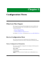
ConÞguration Views
What Is in This Chapter .....................................................................................................3-1
Device ConÞguration View .................................................................................................3-1
Device ConÞguration Information ...............................................................................3-1
Interface ConÞguration Table ......................................................................................3-2
Interface ConÞguration View .............................................................................................3-3
Catalyst Stack System ConÞguration View.......................................................................3-4
Catalyst Stack Chassis Information View...................................................................3-6
Chassis .............................................................................................................3-6
Power Supplies.................................................................................................3-8
Fan....................................................................................................................3-8
Alarms ..............................................................................................................3-9
Catalyst Stack Modules Table......................................................................................3-9
Catalyst Stack Ports Table .........................................................................................3-10
Chapter 4
Event and Alarm Messages
What Is in This Chapter .....................................................................................................4-1
Device Events and Alarms..................................................................................................4-1
Chapter 5
Application View
What Is in This Chapter .....................................................................................................5-1
Common Applications .........................................................................................................5-1
Device Application View .....................................................................................................5-2
Catalyst Stack Application...........................................................................................5-5
Community Strings ......................................................................................................5-8
FDDI Ring Table...........................................................................................................5-9
Catalyst Filter Tables .................................................................................................5-10
MAC Table ............................................................................................................5-10
Vendor Table .........................................................................................................5-11
Protocol Table .......................................................................................................5-11
Test Table..............................................................................................................5-12
Port Table..............................................................................................................5-12
Monitor Information View..........................................................................................5-13
Catalyst TFTP Information View ..............................................................................5-14
Catalyst Trap Receiver Table.....................................................................................5-15
Catalyst VLan Table ...................................................................................................5-15
VLan Ports Table ........................................................................................................5-16
Catalyst VLan Manager .............................................................................................5-16
Selecting a VLan ..................................................................................................5-17
Adding a VLAN ....................................................................................................5-17
Changing a PortÕs VLAN......................................................................................5-18
Removing a VLAN................................................................................................5-18
Discovery Application .................................................................................................5-18
Discovery Cache Table View.......................................................................................5-19
Interface Discovery Status Table ...............................................................................5-19
Ethernet Application ..................................................................................................5-20
iv
Cisco Catalyst 5000/5500 Hub
Management Module Guide
Index
9032208 E4
v
vi
Cisco Catalyst 5000/5500 Hub
Management Module Guide
Figures
Chapter 1
Figure 1-1.
Figure 1-2.
Figure 1-3.
Figure 1-4.
Chapter 2
Figure 2-1.
Figure 2-2.
Figure 2-3.
Figure 2-4.
Figure 2-5.
Figure 2-6.
Figure 2-7.
Chapter 5
Figure 5-1.
Figure 5-2.
Figure 5-3.
Figure 5-4.
Introduction
Using Double-Click Zones to Access SPECTRUM Views ................................... 1-3
Using the Icon Subviews Menu to Access SPECTRUM Views .......................... 1-4
Accessing Module-SpeciÞc Subviews ................................................................... 1-4
SPECTRUM Views Roadmap .............................................................................. 1-5
Device Views
Interface Device View ........................................................................................... 2-2
Interface Icon ........................................................................................................ 2-3
Gauge Control Panel ............................................................................................. 2-7
Cisco Catalyst 5000 Chassis Device View ......................................................... 2-11
Module Icon ......................................................................................................... 2-12
Module IdentiÞcation Labels and Click Zones ................................................. 2-12
Port Label ............................................................................................................ 2-15
Application View
Device Application View (Icon Mode) .................................................................. 5-3
Device Application View (List Mode) ................................................................... 5-4
VLAN Panel ........................................................................................................ 5-17
Add/Remove Buttons .......................................................................................... 5-18
9032208 E4
vii
viii
Cisco Catalyst 5000/5500 Hub
Management Module Guide
Tables
Chapter 2
Table 2-1.
Table 2-2.
Table 2-3.
Table 2-4.
Table 2-5.
Table 2-6.
Chapter 3
Table 3-1.
Table 3-2.
Table 3-3.
Table 3-4.
Table 3-5.
Chapter 4
Table 4-1.
Chapter 5
Table 5-1.
Table 5-2.
Table 5-3.
Table 5-4.
Table 5-5.
Device Views
Administrative Status Label Descriptions........................................................... 2-4
Totals Gauge Mode: Attributes and Corresponding Color .................................. 2-8
Rates Gauge Mode: Attributes and Corresponding Color ................................... 2-8
Module Status Descriptions ................................................................................ 2-13
Port Status Definitions........................................................................................ 2-16
Additional Status Definitions ............................................................................. 2-16
ConÞguration Views
Possible Attach Types............................................................................................ 3-5
Possible System Types for the Cisco Catalyst 5000/5500.................................... 3-6
Module Status Descriptions .................................................................................. 3-9
Possible Port Types.............................................................................................. 3-10
Additional Status Definitions ............................................................................. 3-11
Event and Alarm Messages
Catalyst Switch Events and Alarms..................................................................... 4-1
Application View
Catalyst Stack Application-Specific Icon Subviews Menu Selections ................ 5-5
BRouter Ports Table Field Definitions ................................................................. 5-8
Community Strings View Access Levels .............................................................. 5-9
TFTP Transfer Action Types............................................................................... 5-14
Catalyst Stack Application-Specific Icon Subviews Menu Selections .............. 5-18
9032208 E4
ix
x
Cisco Catalyst 5000/5500 Hub
Management Module Guide
Preface
Use this guide as a reference for the Cisco Catalyst 5000 Hub management
software. Before using this guide, you should be familiar with SPECTRUM
operation. For the purposes of this guide, the Cisco Catalyst 5000 Hubs are
referred to as Òdevices.Ó
What Is in This Guide
The following outlines the organization of the Cisco Catalyst 5000 Hub
Management Module Guide.
Chapter
Description
Chapter 1
Describes the device, the management module and
model types. This chapter also provides
information on accessing device-speciÞc views.
Introduction
Chapter 2
Device Views
Chapter 3
ConÞguration Views
Chapter 4
Event and Alarm Messages
Chapter 5
Application View
Describes the Device views representing the
device.
Describes the ConÞguration views for the device
and the network management information
provided by the views.
Lists and explains the event and alarm messages
generated in the Event Log or Alarm Manager for
the device.
Describes the Application view and applicationspeciÞc information for the device.
9032208 E4
xi
Conventions
Conventions
This guide uses the following conventions:
¥ Menu selections and buttons referenced in text appear in bold; for
example, ConÞguration or Detail.
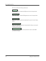
¥ Button names appear in shadowed boxes when introducing paragraphs
that describe their use; for example:
Help
¥ Menu navigation appears in order of selection; for example, Icon
Subviews -> Utilities -> Application.
¥ Referenced chapter titles and section headings appear in italics.
¥ Referenced documents appear in bold italics.
¥ References in blue are hypertext links for online documents.
¥ Cisco Catalyst 5000 Hubs are referred to as Òdevices.Ó
Related SPECTRUM Documentation
When using this guide, you should have a clear understanding of SPECTRUM
functionality and navigation techniques as described in the Administration,
Operation, and following documentation:
Report Generator UserÕs Guide
Getting Started with SPECTRUM 4.0 for Operators
Getting Started with SPECTRUM 4.0 for Administrators
How to Manage Your Network with SPECTRUM
Preface
xii
Cisco Catalyst 5000/5500 Hub
Management Module Guide
Other Related Documentation
Other Related Documentation
Refer to the following documentation for more information on managing TCP/
IP-based networks:
Martin, James, Kathleen Kavanagh Chapman, Joe Leben. Local Area
Networks: Architectures and Implementations, 2d ed. Englewood Cliffs,
NJ: Prentice Hall, 1994.
Rose, Marshall T. The Simple Book: An Introduction to Management of
TCP/IP-based Internets. Englewood Cliffs, NJ: Prentice Hall, 1991.
Stallings, William. Data and Computer Communications, 4th ed. New
York: Macmillan Publishing Company, 1994.
Tanenbaum, Andrew S. Computer Networks, 3d ed. Englewood Cliffs, NJ:
Prentice Hall, 1996.
9032208 E4
Preface
xiii
Other Related Documentation
Preface
xiv
Cisco Catalyst 5000/5500 Hub
Management Module Guide
Chapter 1
Introduction
What Is in This Chapter
This chapter introduces the SPECTRUM management module for the Cisco
Catalyst 5000/5500 Hubs. It describes the following:
¥ The Cisco Catalyst 5000/5500 Hubs
¥ SPECTRUM Model Type
- Accessing SPECTRUM Views
¥ SPECTRUM Views Roadmap
The Cisco Catalyst 5000/5500 Hubs
The Cisco Catalyst 5000 is a Þve slot chassis that provides Copper Distributed
Data Interface/multilevel transmission (CDDI/MLT-3) and single/multimode
Fiber Distributed Data Interface (FDDI) connectivity. The Cisco Catalyst
provides bridging and routing capabilities in a Virtual Local Area Networking
(VLAN) environment. Its architecture supports switched connections to the
following media:
¥
¥
¥
¥
10BaseT and 100BaseT (Fast Ethernet)
4/16 Mbps Token Ring
Copper Distributed Data Interface/Fiber Distributed Data Interface
Asynchronous Transfer Mode (ATM)
The architecture for the 5000 also supports backbone connections for
100BaseT, CDDI/FDDI, and ATM.
9032208 E4
1-1
SPECTRUM Model Type
The Catalyst 5500 is a 13 slot chassis that serves as a high-end switching
platform. Depending on the modules installed, the Catlayst 5500 can be used
in backbone applications as a scaleable Fast Ethernet or ATM switch. The
Catalyst 5500 also supports switched Ethernet, Token Ring and ATM modules
as well as existing Catalyst 5000 and LightStream 1010 modules.
NOTE
The Catalyst 5500 does not have management support for LightStream
boards. To manage these boards the Cisco Lightstream 1010 must be
installed in slot number 13 of the Catalyst 5500 chassis.
SPECTRUM Model Type
SPECTRUM allows you to monitor and manage network devices such as hubs,
routers, and switches through software models (see the AdministratorÕs
Reference for Modeling Instructions) of these devices and their associated
applications. The models you create reside in the SpectroSERVER database,
where they are updated continually with information gathered by polling the
actual devices.
Models are represented visually by icons that appear in various views in
SpectroGRAPH. Icons representing devices provide at-a-glance, color-coded
status information. Both device icons and application icons also provide
mouse-click access to other views that contain detailed conÞguration and
performance information.
SPECTRUM management modules are software packages that provide
templates for creating software models of particular devices or families of
devices. Management modules also include templates for modeling the
applications supported by these devices. Each template, called a model type,
speciÞes attributes that correspond to objects deÞned in the Management
Information Bases (MIBs) that govern the operation of the device or
application to be modeled.The model type names for the Cisco Catalyst 5000/
5500 Hubs are:
¥ HubCat5000
¥ HubCat5500
Refer to the How to Manage Your Network with SPECTRUM guide for
modeling instructions.
Introduction
1-2
Cisco Catalyst 5000/5500 Hub
Management Module Guide
SPECTRUM Model Type
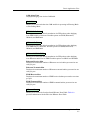
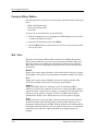
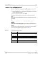
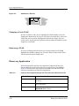
Accessing SPECTRUM Views
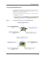
Accessing SPECTRUM Views
Icons and Labels that display information within and icon provide access to
SPECTRUM views. This is done through double-click zones (Figure 1-1), and
Icon Subviews menu selections (Figure 1-2).
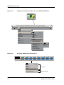
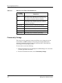
To access the Icon Subviews menu as shown in Figure 1-2, do the following:
1. Highlight the icon or label.
2. From the View menu, select Icon Subviews or click the applicable mouse
button (middle or right). Refer to the Getting Started with SPECTRUM
for OperatorÕs guide for information on conÞguring your mouse.
Figure 1-1.
Using Double-Click Zones to Access SPECTRUM Views
Accesses the ConÞguration view; see
Chapter 3, ConÞguration Views
Accesses the Device Topology view;
refer to the SPECTRUM Views
guide.
Model Name
Accesses the Device view; see
Chapter 2, Device Views.
HubCat5000
Accesses the Performance view;
refer to the SPECTRUM Views
guide.
Accesses the Application view; see
Chapter 5, Application View.
Accesses the ConÞguration view; see
Chapter 3, ConÞguration Views
Accesses the Device view; see
Chapter 2, Device Views.
Model Name
Accesses the Performance view;
refer to the SPECTRUM Views
guide.
HubCat5000
Accesses the Device Topology view;
refer to the SPECTRUM Views
guide.
9032208 E4
Accesses the Application view; see
Chapter 5, Application View.
Introduction
1-3
SPECTRUM Model Type
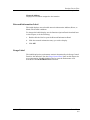
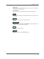
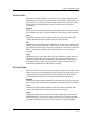
Figure 1-2.
Using the Icon Subviews Menu to Access SPECTRUM Views
Model Name
HubCat5000
Primary Landscape 0x00400000 - VNM Host - LAN of type Landscape
*
File
View
Help?
Go Back
Go Up
Icon Subviews
View Path
New View
Jump to View
View History...
Current View Information...
Notes
Jump by Name...
Zoom
Map Hierarchy
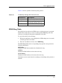
Figure 1-3.
Close
ctrl+c
Navigate
Alarms
Performance
Notes...
Utilities
Zoom
Application
Chassis Information
Device
DevTop
Acknowledge
Flash Green Enabled
Configuration
Model Information
Primary Application
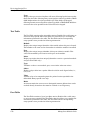
Accessing Module-SpeciÞc Subviews
1
On
wsx5010
1
OK
9 Other
2 Other
3 Other
4 Other
5 Other
6 Other
7 Other
8 Other
10 Other
11 Other
12 Other
13 Other
14 Other
15 Other
16 Other
Close
Ctrl +C
Navigate
Alarms
Performance
Notes...
Utilities
Module Notes
Module Configuration
Introduction
1-4
Interface
Chassis
Common
Module-SpeciÞc
Cisco Catalyst 5000/5500 Hub
Management Module Guide
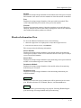
SPECTRUM Views Roadmap
SPECTRUM Views Roadmap
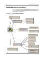
Figure 1-4 shows a ÒroadmapÓ of the SPECTRUM views for this device. These
views are accessible from double-click zones (Figure 1-1) and Icon Subviews
menus (Figure 1-2, and Figure 1-3).
Figure 1-4.
SPECTRUM Views Roadmap
Performance view; refer to the
SPECTRUM Views guide.
Interface Device view
Device views; see Chapter 2,
Device Views
Chassis Device view
Device ConÞguration view
Model Name
ConÞguration view; see
Chapter 3,ConÞguration
Views
HubCat5000
System ConÞguration view
Catalyst Stack Application
Discovery Application
Ethernet Application
Application view; see
Chapter 5, Application
View
FDDI Application
Bridging Application; refer to
the Bridging Applications
Reference.
DevTop view; refer to the
SPECTRUM Views reference.
MIB II Application; refer to the
MIB II Applications
Reference.
9032208 E4
Introduction
1-5
SPECTRUM Views Roadmap
Introduction
1-6
Cisco Catalyst 5000/5500 Hub
Management Module Guide
Chapter 2
Device Views
What Is in This Chapter
This chapter describes the following Device views and subviews available for
the Cisco Catalyst 5000/5500 Hubs:
¥ Interface Device View
¥ Chassis Device View
See Chapter 1, Introduction, for information on Accessing SPECTRUM Views.
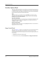
Interface Device View
This section describes the Interface Options panel and the Interface icons
displayed in the Interface Device view. This view provides dynamic
conÞguration and performance information for each interface on this device. If
the conÞguration changes, SPECTRUM modiÞes the Device view after the
next polling cycle to reßect the new conÞguration. This view also provides a
Device icon which allows you to monitor the deviceÕs operation and access
other device-speciÞc views. Figure 2-1 shows an example of the Interface
Device view.
9032208 E4
2-1
Interface Device View
Figure 2-1.
Interface Device View
Primary Landscape 0x00400000 - VNM Host - HubCat5000 of type Primary
* File
View
Help?
System Up Time
Network Address
Model Name
Contact
Manufacturer
Description
Device Type
Location
Serial Number
Primary-Application
Model Name
Find
HubCat5000
Network Information
Phy Addr
Interface Description
Device Icon
Interface Options Panel
Interface Icons
1 ON
5
OFF
9
OFF
13
OFF
Ethernet
ETHERNET
ETHERNET
ETHERNET
0:01D:17:2F:3C
0:01D:17:2F:3C
0:01D:17:2F:3C
0:01D:17:2F:3C
0
0
0
0
2
ON
OFF
6
10 OFF
OFF
14
SLIP
ETHERNET
ETHERNET
ETHERNET
0:01D:17:2F:3C
0:01D:17:2F:3C
0:01D:17:2F:3C
0:01D:17:2F:3C
0
0
OFF
3
0
OFF
7
11
0
OFF
OFF
15
ETHERNET
ETHERNET
ETHERNET
ETHERNET
0:01D:17:2F:3C
0:01D:17:2F:3C
0:01D:17:2F:3C
0:01D:17:2F:3C
0
0
ON
4
Device Views
2-2
ADDRESS
0
OFF
8
12
0
OFF
16
OFF
ETHERNET
ETHERNET
ETHERNET
ETHERNET
0:01D:17:2F:3C
0:01D:17:2F:3C
0:01D:17:2F:3C
0:01D:17:2F:3C
0
0
0
0
Cisco Catalyst 5000/5500 Hub
Management Module Guide
Interface Device View
Interface Icons
Interface Icons
These icons represent the interfaces or ports for this device. The icons identify
the type of interface or port and provide statistical information. Figure 2-2
shows an example of an interface icon, its Icon Subviews menu, and its labels/
double-click zones.
NOTES
The callouts (a through f) displayed in the illustration below identify the
label and the view to which it provides double-click access. Example:
Administrative Status Label/IF Status view displays the administrative
status and provides double-click access to the IF Status view.
The menu displayed in the illustration is the Icon Subviews menu for that
Interface icon.
Figure 2-2.
Interface Icon
Icon Subviews Menu:
Close
Ctrl +c
Navigate
Alarms
Performance
Notes...
Utilities
Detail
If Status
IF Configuration
IF Address Translation Table
Network Information Panel
Thresholds
Model Information
(b)
(a)
ON
1
Ethernet
0:01D:17:2F:3C
(c)
(d)
0
(e)
(f)
a. Interface Label
b. Administrative Status Label/Interface Status View
c. Interface Type Label/Interface ConÞguration View
d. MAC Address Label/Interface Address Translation Table
e. Network Information Label/Network Information Panel
f.
9032208 E4
Gauge Label/Performance View
Device Views
2-3
Interface Device View
Interface Icons
Interface Label
This label displays the interface (port) number.
Administrative Status Label
This label displays the status of this interface. Double-click this label to open
the Interface Status view which allows you to view the operational state of
that interface, and select the administrative status (enable or disable the
port). Table 2-1 lists the possible states and their descriptions.
Table 2-1.
Administrative Status Label Descriptions
Color
Status
Description
Green
ON
Port is operational.
Blue
OFF
Port is off.
Yellow
TESTING
Port is in the test mode.
Interface Type Label
This label displays the interface type. Some of the possible interface types are
Ethernet, FDDI, T1, PPP, and Reg1822.
MAC Address Label
This label displays the MAC address of this device. Double-click this label to
open the Interface Address Translation table.
Interface Address Translation Table
This table cross-references device IP addresses to device MAC (Physical)
addresses for selected nodes between networks. Double-click any column
entry to open an address-speciÞc Address Translation Table Information view.
The Interface Address Translation Table provides the following information:
Interface Index
A list of interfaces held by the device.
Physical Address
Displays the physical (MAC) address of the interface.
Device Views
2-4
Cisco Catalyst 5000/5500 Hub
Management Module Guide
Interface Device View
Interface Icons
Network Address
Displays the IP address assigned to the interface.
Network Information Label
This label displays user-selectable network information (Address, Name, or
Mask). The default is Address.
To change this labelÕs display, use the Interface Options Panel described later
in this chapter, or do the following:
1. Double-click the label to open the Network Information Panel.
2. Click the network information entry you wish to display.
3. Click OK.
Gauge Label
This label displays the performance statistic determined by the Gauge Control
Panel for this interface. (See the Gauge Control Panel later in this chapter for
more information.) Double-click this label to open the Performance view
described in the SPECTRUM Views reference.
9032208 E4
Device Views
2-5
Interface Device View
Interface Options Panel
Interface Options Panel
This area of the Interface Device view allows you to modify the presentation of
a highlighted Logical Interface icon. Double-click a non-text area of this panel
to open the Gauge Control Panel, described later in this section. The Interface
Options panel provides the following information:
Find
This button allows you to Þnd an entry. Click Find to open the text entry
dialog box. In the Dialog Box, enter the string to search for. Not all column
headings will activate the Find button.
Network Information
This menu button allows you to select the type of information displayed in the
Network Information label of the highlighted icon. Possible selections are
ADDRESS, NAME, or MASK.
Interface Description
This Þeld provides a description of the highlighted interface. If no interface is
highlighted, this Þeld is empty.
Gauge Control Panel
This panel (Figure 2-3) allows you to change the type of statistical information
displayed on the Gauge label of the Interface icon. To access the Gauge
Control Panel double-click the background of the Interface Options panel or do
the following:
1. Highlight the Interface Options panel.
2. From the View menu, select Icon Subviews -> Gauge Control Panel.
Device Views
2-6
Cisco Catalyst 5000/5500 Hub
Management Module Guide
Interface Device View
Interface Options Panel
Figure 2-3.
Gauge Control Panel
Gauge Control Panel
Gauge Mode
Rates
Totals
Percentages
Gauge Type
Numeric
Linear
Selected Attribute
Load
Load In
Load Out
Packet Rate
Packet In Rate
Packet Out Rate
% Error Rate
% Error In Rate
Apply
Keep Settings
Reset
Close
Gauge
Buttons
Default
The Gauge Control Panel provides the following:
¥
¥
¥
¥
Gauge Mode
Selected Attribute
Gauge Type
Gauge Buttons
Gauge Mode
This area allows you to select the type of information shown on the Gauge
Label of the interface icon: Totals, Rates, or Percentages. The Percentages
selection displays the percentage of the selected interface compared to the rest
of the interfaces.
The color displayed on the Gauge Label depends upon the particular mode
and statistical attribute selected. Table 2-2 and Table 2-3 provide a list of
attributes and their corresponding colors for the Totals mode and Rates mode
respectively.
9032208 E4
Device Views
2-7
Interface Device View
Interface Options Panel
Table 2-2.
Totals Gauge Mode: Attributes and Corresponding Color
Selected
Attribute
Table 2-3.
Color
In Errors
Orange
Out Errors
Orange
In Packets
Blue
Out Packets
Blue
Unknown Protocols
Yellow
In No Resource
Tan
Out No Resource
Tan
In Octets
Green
Out Octets
Green
Rates Gauge Mode: Attributes and Corresponding Color
Selected
Attribute
Color
Load
Green
Load In
Green
Load Out
Green
Packet Rate
Blue
Packet In Rate
Blue
Packet Out Rate
Blue
Error Rate
Orange
Error In Rate
Orange
Error Out Rate
Orange
Discard Rate
Tan
Discard In Rate
Tan
Discard Out Rate
Tan
Selected Attribute
This area of the Gauge Control Panel allows you to select the statistical
attribute displayed on the Interface iconÕs Gauge label. The label changes
color to reßect the attribute selected.
Device Views
2-8
Cisco Catalyst 5000/5500 Hub
Management Module Guide
Interface Device View
Gauge Type
This area of the Gauge Control Panel allows you to select either a numeric or
linear display on the Gauge Label.
Gauge Buttons
This area of the Gauge Control Panel provides the following buttons:
Apply
Applies the current settings to the Gauge label temporarily, but does not save
the settings.
Reset
Returns the settings to the previously saved values.
Keep Settings
Saves the current settings while SpectroGRAPH is running. Settings return
to default when you restart SpectroGRAPH.
Close
Closes the Gauge Control Panel.
Default
Returns the settings to the SPECTRUM default.
9032208 E4
Device Views
2-9
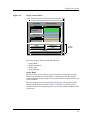
Chassis Device View
Chassis Device View
This view provides information about the device and the modules it manages.
The Chassis Device view is divided into two sections. The top section provides
information about the Cisco Catalyst 5000/5500 Hub as a whole. The bottom
section provides information about the individual modules installed in the
chassis. Figure 2-4 shows an example of the Chassis Device view for this
device.
Device Views
2-10
Cisco Catalyst 5000/5500 Hub
Management Module Guide
Chassis Device View
Module Icons
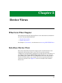
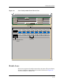
Figure 2-4.
Cisco Catalyst 5000 Chassis Device View
Primary Landscape 0x00400000 - VNM Host - Machine
*
File
View
Help?
Net Addr
Model Name
Sys Up Time
Contact
Manufacturer
Description
Device Type
Location
Prime-App
Serial Number
Module Icon
1
On
wsx5009
1
1
On
wsx5010
2 Other
3 Other
4 Other
5 Other
6 Other
7 Other
8 Other
9 Other
10 Other
11 Other
12 Other
13 Other
14 Other
15 Other
16 Other
1
2 Other
3 Other
4 Other
5 Other
6 Other
7 Other
8 Other
OK
OK
Module IdentiÞcation
Labels
Port Icon
Module Icons
These icons represent the modules inserted into the chassis. The icons identify
the type of interface or port and provide statistical information. Figure 2-5
shows an example of a Module icon.
9032208 E4
Device Views
2-11
Chassis Device View
Module Icons
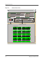
Figure 2-5.
Module Icon
Module IdentiÞcation Label
1
On
wsx5010
1
OK
9
Other
2
Port Icons
3
Other
10 Other
Other
11 Other
4
Other
12 Other
5
Other
13 Other
6
Other
14 Other
7
Other
15 Other
8
Other
16 Other
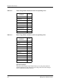
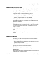
Figure 2-6 shows the Module IdentiÞcation labels and the views accessed from
the Icon Subviews menu.
NOTES
The callouts displayed in the illustration below identify the label and the
view to which it provides double-click access. Example: Module Number
Label/Module Notes view displays the Module Number and provides doubleclick access to the Module Notes view.
The Icon Subviews menu is speciÞc to the icon selected.
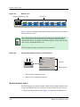
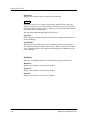
Figure 2-6.
Module IdentiÞcation Labels and Click Zones
a
b
1
On
wsx5010
1
OK
9
Other
Close
Ctrl +C
Navigate
Alarms
Performance
Notes...
Utilities
Module Notes
Module Configuration
Common
Device-SpeciÞc
a. Module Number Label/Module Notes
b. Module Status Label/Module Table View
Module Number Label
This label displays the module number. Double-click the Model Number label
to access the Module Notes view used for recording module-speciÞc notes, or:
1. Within the Chassis Device view (Figure 2-4) highlight the Module icon.
Device Views
2-12
Cisco Catalyst 5000/5500 Hub
Management Module Guide
Chassis Device View
Module Icons
2. From the Icon Subviews menu, select Module Notes.
Module Status Label
This label displays the status of the module. Possible states are On, Off and
Test. Double-click the Module Status label of the Module Icon to access the
Module Table view, or do the following:
1. Within the Chassis Device view (Figure 2-4) highlight the Module icon.
2. From the Icon Subviews menu, select Module ConÞguration.
Module Table View
This view displays module speciÞc conÞguration information. It is divided into
the two sections described below.
Module
This area of the Module Table view provides the following information:
Index
Displays the slot number in which this module is inserted in the chassis. Valid
entries are 1 to the maximum number of slots in this chassis.
Type
Displays the type of module.
Serial Nbr
Displays the serial number for this module.
Name
Displays the user-deÞned or default model name for this module.
Status
Displays the current status of this module. Table 2-4 shows the possible
states.
Table 2-4.
9032208 E4
Module Status Descriptions
Color
Status
Description
Blue
Other
None of the following
Green
OK
Status is okay
Yellow
MinorFault
Minor problem
Red
MajorFault
Major problem
Device Views
2-13
Chassis Device View
Num Ports
Displays the number of ports supported by this module.
Action
This button allows you to initiate action on the module. Reset causes the
moduleÕs control logic to be reset. Enable or Disable activates or deactivates
the module. Other results in an error. After an action has been initiated, this
button displays the Other option.
The following additional Þelds appear in this view:
Sub Type
Shows the type of daughterboard attached to this module. Possible types are
Other and Empty.
Test Results
Displays the test results from the last completed self test of this module. A
zero indicates that the module passed all tests. Bits set in the result indicate
error conditions. Refer to the hardware documentation for deÞnitions of the
error conditions.
Versions
This area of the Module Table view provides the following information:
Hardware
Displays the hardware version for this module.
Firmware
Displays the firmware version for this module.
Software
Displays the software version for this module.
Device Views
2-14
Cisco Catalyst 5000/5500 Hub
Management Module Guide
Chassis Device View
Port Icons
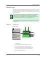
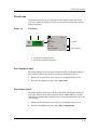
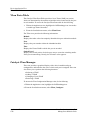
Port Icons
This label represents a port or interface on the module within this device.
Figure 2-7 shows an example of a port icon, its Icon Subviews menu, and its
double-click zones.
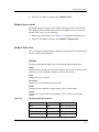
Figure 2-7.
Port Label
a
b
1
OK
Close
Navigate
Alarms
Performance
Notes...
Utilities
Port Notes
Port Configuration
Ctrl +C
Common
Device-SpeciÞc
a. Port Number Label/Port Notes
b. Port Status Label/Port Table View
Port Number Label
This label displays the port number. Double-click the Port Number Label to
access the Port Notes view, used for recording port-speciÞc notes, or:
1. Within the Chassis Device view (Figure 2-4) highlight the Port icon.
2. From the Icon Subviews menu, select Port Notes.
Port Status Label
This label displays the status of the port. This label also displays the device
port types. Some of the possible types are; Other, CDDI, FDDI, etc. Doubleclick the Port Status label of the Port Icon to access the Port Table view, or do
the following:
1. Within the Chassis Device view (Figure 2-4) highlight the Port icon.
2. From the Icon Subviews menu, select Port ConÞguration.
9032208 E4
Device Views
2-15
Chassis Device View
Port Icons
Port Table View
This view provides the following information:
Module
Displays the slot number in which this module is inserted in the chassis. Valid
entries are 1 to the maximum number of slots in this chassis.
Type
Displays the port type in terms of the medium it supports.
Speed
Displays the base speed of this port in bits per second.
Name
Displays the default model name for this module.
Index
Displays the port number.
Status
Displays the current status of this module. Table 2-5 shows the possible
states:
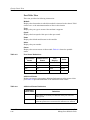
Table 2-5.
Port Status DeÞnitions
Operational
Status
Administrative
Status
Text
Display
Color
ON
ON
ON
Green
OFF
OFF
OFF
Blue
OFF
ON
OFF
Yellow
Testing
Testing
Test
Red
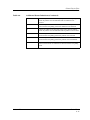
Additional Status
Displays an integer representing additional information on the status of this
port. Table 2-6 provides deÞnitions of the additional status values.
Table 2-6.
Additional Status DeÞnitions
Additional
Status Value
Device Views
2-16
DeÞnition
0
Initial Value, or no activity was detected on the port in the last
polling period.
1
At least one packet was transmitted by the port in the last polling
period. No packets were received and no collisions were detected.
Cisco Catalyst 5000/5500 Hub
Management Module Guide
Chassis Device View
Port Icons
Table 2-6.
9032208 E4
Additional Status DeÞnitions (Continued)
2
At least one packet was received by the port in the last polling
period. No packets were transmitted and no collisions were
detected.
3
At least one packet was transmitted, and at least one packet was
received in the last polling period. No collisions were detected.
4
At least one collision was detected on the port in the last polling
period. No packets were transmitted and no packets were received.
5
At least one packet was transmitted, and at least one collision was
detected in the last polling period. No packets were received.
6
At least one packet was received, and at least one collision was
detected in the last polling period. No packets were transmitted.
7
At least one packet was transmitted, at least one packet was
received, and at least one collision was detected in the last polling
period.
Device Views
2-17
Chassis Device View
Port Icons
Device Views
2-18
Cisco Catalyst 5000/5500 Hub
Management Module Guide
Chapter 3
ConÞguration Views
What Is in This Chapter
This chapter describes the following ConÞguration views available for the
device and its interfaces. These views display network conÞguration and
operating information.
¥ Device ConÞguration View
¥ Interface ConÞguration View
¥ Catalyst Stack System ConÞguration View
See Chapter 1, Introduction, for information on Accessing SPECTRUM Views.
Device ConÞguration View
This view provides two areas of information on the conÞguration and
operating status of this device. They are described in the following sections.
Device ConÞguration Information
This section of the Device ConÞguration view displays the following devicespeciÞc information:
Device Name
Displays the user-deÞned or default name for this device.
Contact Status
Displays the status of the device. Possible states are Established, Lost, or
Initial.
9032208 E4
3-1
Device ConÞguration View
Number of Interfaces
Displays the number of ports for the device.
Router Redundancy
This button allows you to enable (true), or disable (false) redundancy for this
interface. By default it is set to be true.
IF Address Translation
This button accesses the IF Address Translation Table. This table crossreferences device IP addresses to device MAC (Ethernet) addresses for
selected nodes between networks. Double-click a column entry to open an
address-speciÞc Address Translation Table Information view, which allows
you to alter the index or addresses.
ReconÞgure
This button allows you to update the Device ConÞguration view to reßect any
changes that have been made to the devices in the chassis.
Interface ConÞguration Table
This table within the Device ConÞguration view provides the following
conÞguration information for the device and each port:
Index
Displays the interface or port number.
Description
Provides a description of the interface or port.
Type
Displays the type of hardware interface or port. Some of the possible types are
Ethernet, FDDI, T1, PPP, and Reg1822.
Bandwidth
Displays the estimated bandwidth of the interface measured in bits per
second. For interfaces that do not vary in bandwidth, or for which no accurate
estimate can be made, a nominal bandwidth is provided
Physical Address
Displays the physical (MAC) address of the interface or port.
Operation Status
Displays the current operational state of this interface or port (Up, Down, or
Testing).
Admin. Status
Displays the administrative status for this interface. Possible states are: On,
Off, and Testing.
ConÞguration Views
3-2
Cisco Catalyst 5000/5500 Hub
Management Module Guide
Interface ConÞguration View
Last Change
Displays the value of sysUpTime at the time the interface entered its current
operational state. If the current state was entered prior to the last reinitialization of the local network management subsystem, then this object
contains a zero value.
Queue Length
Displays the length of the outbound packet queue in packets.
Packet Size
Displays the largest Maximum Transmission Unit (MTU) that can be
transmitted or received by the port, measured in octets.
Interface ConÞguration View
This view provides device conÞguration information.
To access this view, do the following:
1. Within the Interface Device view, highlight the Interface icon.
2. From the Icon Subviews menu, select IF ConÞguration.
This view provides the following information:
Operation Status
Displays the current operating status of the interface or port. Possible values
are On, Off, and Testing.
Admin. Status
Displays the current administrative state of the interface or port. Possible
values are On, Off, and Testing.
Last Change
Displays the value of sysUpTime at the time the interface entered its current
operational state. If the current state was entered prior to the last reinitialization of the local network management subsystem, then this object
contains a zero value.
Network Name/Address
Displays the network name/address for this interface or port.
Physical Address
Displays the physical (MAC) address of the interface or port.
Bandwidth
Displays the estimated bandwidth of the interface measured in bits per
second. For interfaces that do not vary in bandwidth or for which no accurate
estimate can be made, a nominal bandwidth is provided.
9032208 E4
ConÞguration Views
3-3
Catalyst Stack System ConÞguration View
Packet Size
Displays the largest Maximum Transmission Unit (MTU) that can be
transmitted or received by the port, measured in octets.
Queue Length
Displays the length of the outbound packet queue in packets.
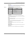
Catalyst Stack System ConÞguration View
This view and its subviews provide device conÞguration information.
To access this view, do the following:
1. Within the Application view, highlight the CATStackApp icon (icon mode)
or model type name (list mode).
2. From the Icon Subviews menu, select ConÞguration.
This view provides the following information:
Mgmt Type
Displays the type of network management running on the device. Possible
management types include: ÒOtherÓ (none of the following), ÒsnmpV1Ó, ÒsmuxÓ
(SNMP MUX sub-agent), and ÒsnmpV2V1Ó (bi-lingual SNMP).
Net Mask
Displays the subnet mask for the device.
Broadcast
Displays the broadcast address of the device.
Baud Rate
Displays the baud rate of the deviceÕs RS-232 port in bits per second.
Clear Mac Time
Displays the amount of time (in hundredths of a second) since the MAC
counters were last cleared.
Clear MAC
Allows you to initiate the clearing of the MAC counters and to reset the Clear
MAC value to zero.
Clear Port Time
Displays the amount of time, displayed in hundredths of a second, since the
port counters were last cleared.
Clear Ports
Allows you to initiate the clearing of the port counters and to reset the Clear
Port value to zero.
ConÞguration Views
3-4
Cisco Catalyst 5000/5500 Hub
Management Module Guide
Catalyst Stack System ConÞguration View
Attach Type
This button allows you to change the attachment type of the FDDI connection
to the device. Table 3-1 shows the possible attachment types. New attach type
settings will not take effect until the concentrator is reset.
Table 3-1.
Possible Attach Types
Attach Type
DeÞnition
Other
None of the following.
DualAttach
The Þrst FDDI port is conÞgured as an A port,
the second as a B port.
SingleAttach
The Þrst FDDI port is conÞgured as an S port,
the second as an M port.
NullAttach
The Þrst two FDDI ports are conÞgured as M
ports.
Insert Mode
This button allows you to select the mode for inserting M-ports into the
concentrator ring. Possible insertion modes are: Other (none of the following),
Standard, Scheduled, and Graceful.
Reset
This button allows you to initiate a reset of the control logic of all modules in
the device. The default is Other.
TrafÞc
Displays the value of the trafÞc meter, shown as a percentage of bandwidth
utilization on the network for the previous polling interval.
Enable Redirects
Allows you to select whether the device is able to send or receive ICMP
redirect messages.
Enable Modem
Allows you to select whether this deviceÕs RS-232 port modem control lines are
enabled or disabled.
Enable Rmon
Allows you to select whether this SNMP agent supports the RMON MIB.
9032208 E4
ConÞguration Views
3-5
Catalyst Stack System ConÞguration View
ARP Aging Time
Displays the aging Time in milliseconds for the ARP Table.
Chassis
Opens the Catalyst Stack Chassis Information view described later in this
section.
Modules
Opens the Catalyst Stack Modules Table, described later in this section.
Ports
Opens the Catalyst Stack Ports Table described later in this section.
Catalyst Stack Chassis Information View
This view provides information about the physical device. To access this view,
click the Chassis button in the Catalyst Stack System ConÞguration view.
The Chassis Information view provides the following information:
Chassis
This section of the Chassis Information view provides the following hardware
information about the device:
Model
Displays the manufacturerÕs model number for the chassis.
System Type
Displays the type of chassis system. Table 3-2 lists the possible system types
for this device.
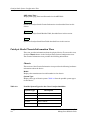
Table 3-2.
Possible System Types for the Cisco Catalyst 5000/5500
System Type
ConÞguration Views
3-6
Description
wsx5009
Supervisor Module, 2 100BaseTX
wsx5013
24 port 10BaseT
wsx5011
12 Port 10BaseFL Multi Mode
wsx5010
24 Port 10BaseT
wsx5113
12 port 100BaseTX
Cisco Catalyst 5000/5500 Hub
Management Module Guide
Catalyst Stack System ConÞguration View
Catalyst Stack Chassis Information View
Table 3-2.
Possible System Types for the Cisco Catalyst 5000/5500
wsx5101
1 Dual Attach Multi Mode FDDI
wsx5103
1 Dual Attach CDDI
wsx5104
1 Dual Attach Single Mode FDDI
wsx5105
1 Dual Attach Multi Mode FDDI
wsx5155
1 Port Multi Mode OC-3 ATM
wsx5154
1 Port Single Mode OC-3 ATM
wsx5153
1 Port UTP OC-3 ATM
wsx5111
12 Port 100BaseFX Multi Mode
wsx5213
12 Port 10/100BaseTX
wsx5020
48 Port 4 Segment 10BaseT
wsx5006
Supervisor Module, 2 100BaseFX
Multi Mode
wsx5005
Supervisor Module, 2 100BaseFX
Single Mode
wsx5509
Supervisor Module II, 2 100BaseTX
wsx5506
Supervisor Module II, 2 100BaseFX
Multi Mode
wsx5505
Supervisor Module II, 2 100BaseFX
Single Mode
wsx5156
1 Dual Phy UTP OC-3 ATM
wsx5157
1 Dual Phy Single Mode OC-3 ATM
wsx5158
1 Dual Phy Multi Mode OC-3 ATM
wsx5114
6 Port Single Mode 6 Port Multi
Mode 100BaseFX
wsx5223
24 Port 3 Segment 100BaseTX
wsx5224
24 Port 10/100BaseTX
wsx5012
48 Port 10BaseT
wsx5302
VLAN Router
wsx5213a
12 Port 10/100BaseTX
wsx5201
12 Port 100BaseFX Multi Mode
wsx5203
12 Port 10/100BaseTX
Backplane
Displays the chassis backplane type for the device. Possible backplane types
are Other, FDDI, and FDDI+Ethernet.
9032208 E4
ConÞguration Views
3-7
Catalyst Stack System ConÞguration View
Catalyst Stack Chassis Information View
Number Slots
Displays the number of slots for plug-in modules in the device.
Power Supplies
This section of the Chassis Information view provides the following
information about the devices power supplies:
#1 Type
Displays the type of power supply installed as the Þrst power supply for the
device. Possible power supply types are: Other, None, 50w, 200w, 600w, 80w,
and 130w.
#1 Status
Displays the current status of the power supply installed as the Þrst power
supply. Possible states are: Other, OK, MinorFault, and MajorFault. For more
information on fault conditions, refer the Test Results Þeld.
#1 Test Results
Displays the current status of the test result for the power supply installed as
the Þrst power supply. A zero indicates that the power supply passed all tests.
#2 Type
Displays the type of power supply installed as the second power supply for the
device. Possible power supply types are: Other, None, 50w, 200w, 600w, 80w,
and 130w.
#2 Status
Displays the current status of the power supply installed as the second power
supply. Possible statuses are: Other, OK, MinorFault, and MajorFault.
#2 Test Results
Displays the current status of the test result for the power supply installed as
the second power supply. A zero indicates that the power supply passed all
tests.
Fan
This section of the Chassis Information view provides the following
information about the deviceÕs cooling fan:
Status
Displays the current status of the deviceÕs fan. Possible states are Other, OK,
MinorFault, and MajorFault.
Test Result
Displays the test results from the last completed test of the deviceÕs fan. A
zero indicates that the fan passed all tests. Refer to your hardwareÕs
documentation for deÞnitions of the error conditions.
ConÞguration Views
3-8
Cisco Catalyst 5000/5500 Hub
Management Module Guide
Catalyst Stack System ConÞguration View
Catalyst Stack Modules Table
Alarms
The Alarms portion of the Chassis Information view provides information
about any physical status alarms detected for the device. Possible alarm
states for each of the Þelds listed below are Off and On.
Temp
Displays the current status of the temperature alarm for this device.
Minor
Displays the current status of the minor alarms for this device.
Major
Displays the current status of the major alarms for this device.
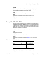
Catalyst Stack Modules Table
This table provides module identiÞcation information. To access the Catalyst
Stack Modules table, click the Modules button in the Catalyst Stack System
ConÞguration view. Double-click any table entry to access the Catalyst Stack
Module Table view for that entry. The Catalyst Stack Modules table provides
the following information for each module:
Index
Displays the slot number in which this module is inserted in the chassis. Valid
entries are 1 to the maximum number of slots in this chassis.
Type
Displays the type of module.
Serial Nbr
Displays the serial number for this module.
Status
Displays the current status of this module. Table 3-3 shows the possible
states.
Table 3-3.
Module Status Descriptions
Color
Status
Description
Blue
Other
None of the following
Green
OK
Status is ok
Yellow
MinorFault
Minor problem
Red
MajorFault
Major problem
Name
Displays the user-deÞned or default model name for this module.
9032208 E4
ConÞguration Views
3-9
Catalyst Stack System ConÞguration View
Catalyst Stack Ports Table
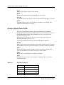
Ports
Displays the number of ports for the module.
Model
Displays the manufacturerÕs model number for the chassis.
Sort On
This button allows you to select one of the table column headings as a sort key.
Order
This button allows you to sort the table in ascending or descending order
within the selected Sort On category.
Catalyst Stack Ports Table
This table provides the list of port entries determined by the number of
modules in the chassis and the number of ports in each module. To access the
Catalyst Stack Ports table, click the Ports button in the Catalyst Stack
System ConÞguration view.
Double-click any table entry to access the entry-speciÞc Port Table view,
described in Chapter 2, Device Views.
The Catalyst Stack Ports table provides the following information:
Module
Displays the unique integer identiÞer of the module where this port is located.
This number is the same as the slot number in which the module is installed.
Index
Displays the unique integer identiÞer of this port within its module. This
value is determined by the location of the port on the module.
Name
Displays the user-deÞned name assigned to this port.
Type
IdentiÞes the port in terms of the medium it supports. Table 3-4 lists the
possible port types.
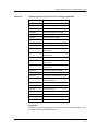
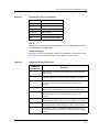
Table 3-4.
Possible Port Types
Port Type
ConÞguration Views
3-10
Description
Other
None of the following
cddi
CDDI (UTP FDDI)
fddi
Multi Mode Þber FDDI
tppmd
ANSI standard UTP FDDI
Cisco Catalyst 5000/5500 Hub
Management Module Guide
Catalyst Stack System ConÞguration View
Catalyst Stack Ports Table
Table 3-4.
Possible Port Types (Continued)
mlt3
MLT-3 UTP FDDI
sddi
STP FDDI
smf
Single Mode Þber FDDI
E10BaseT
UTP Ethernet
E10BaseF
Fiber Ethernet
E100BaseTX
Fast UTP Ethernet
scf
Small-connector Þber FDDI
Status
Displays the current operational state of this port. Possible states are Other,
Ok, MinorFault, and MajorFault.
Additional Status
Displays an integer representing additional information on the status of this
port. Table 3-5 provides deÞnitions of the additional status values.
Table 3-5.
Additional Status DeÞnitions
Additional
Status Value
9032208 E4
DeÞnition
0
Initial Value, or no activity was detected on the port in the last
polling period.
1
At least one packet was transmitted by the port in the last polling
period. No packets were received and no collisions were detected.
2
At least one packet was received by the port in the last polling
period. No packets were transmitted and no collisions were
detected.
3
At least one packet was transmitted, and at least one packet was
received in the last polling period. No collisions were detected.
4
At least one collision was detected on the port in the last polling
period. No packets were transmitted and no packets were
received.
5
At least one packet was transmitted, and at least one collision
was detected in the last polling period. No packets were received.
6
At least one packet was received, and at least one collision was
detected in the last polling period. No packets were transmitted.
7
At least one packet was transmitted, at least one packet was
received, and at least one collision was detected in the last polling
period.
ConÞguration Views
3-11
Catalyst Stack System ConÞguration View
Catalyst Stack Ports Table
Sort On
This button allows you to select one of the table column headings as a sort key.
Order
This button allows you to sort the table in ascending or descending order
within the selected Sort On category.
ConÞguration Views
3-12
Cisco Catalyst 5000/5500 Hub
Management Module Guide
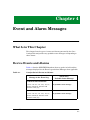
Chapter 4
Event and Alarm Messages
What Is in This Chapter
This chapter lists the types of events and alarms generated by the Cisco
Catalyst Hub and provides any probable cause messages corresponding to
these alarms.
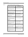
Device Events and Alarms
Table 4-1 lists the SPECTRUM database directory paths (in bold) and the
messages displayed for the Event Log and Alarm Manager when applicable.
Table 4-1.
Catalyst Switch Events and Alarms
Message in the Event Log
Alarm View
Probable Cause Message
CsEvFormat/Event00010306
{d Ò%w- %d %m-, %Y - %TÓ} - A(n) {t}
device, named {m}, has been cold
started. (event [{e}])
No probable cause message.
CsEvFormat/Event00010307
{d Ò%w- %d %m-, %Y - %TÓ} - A(n) {t}
device, named {m}, has been warm
started. (event [{e}])
No probable cause message.
9032208 E4
4-1
Device Events and Alarms
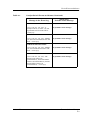
Table 4-1.
Catalyst Switch Events and Alarms (Continued)
Message in the Event Log
Alarm View
Probable Cause Message
CsEvFormat/Event00010308
CsPCause/Prob00010308
{d Ò%w- %d %m-, %Y - %TÓ} - A(n) {t}
device, named {m}, has detected a
communication Link Down. (event
[{e}])
Communication link is down.
CsEvFormat/Event00010309
{d Ò%w- %d %m-, %Y - %TÓ} - A(n) {t}
device, named {m}, has detected a
communication Link Up. (event [{e}])
No probable cause message.
CsEvFormat/Event0001030a
CsPCause/Prob0001030a
{d Ò%w- %d %m-, %Y - %TÓ} - A(n) {t}
device, named {m}, has detected an
Authentication Failure.
(event [{e}])
Authorization failure. Other user is
trying to connect to device with an
invalid community string.
CsEvFormat/Event0001030b
CsPCause/Prob0001030b
{d Ò%w- %d %m-, %Y - %TÓ} - A(n) {t}
device, named {m}, has detected an
EGP Neighbor Loss. EGP Neighbor IP
address is {0 1}.
(event [{e}])
Lost contact with EGP neighbor.
CsEvFormat/Event00010401
CsPCause/Prob00010401
{d Ò%w- %d %m-, %Y - %TÓ} - Device
{m} of type {t} is created with an IP
address already used by another
model. (event [{e}])
DUPLICATE IP ADDRESS
CsEvFormat/Event00010402
CsPCause/Prob00010402
{d Ò%w- %d %m-, %Y - %TÓ} - Device
{m} of type {t} is created with a
physical (Mac) address already used
by another model. (event [{e}])
DUPLICATE PHYSICAL ADDRESS
The model has the same IP address as
that of some other model.
The model has the same Physical
address (Mac address) as that of some
other model.
CsEvFormat/Event011c0000
{d "%w- %d %m-, %Y - %T"} - A
Catalyst switch, {t} (name - {m}) has
been reloaded. SystemUpTime = {I 1}.
- (event [{e}])
Event and Alarm Messages
4-2
No probable cause message.
Cisco Catalyst 5000/5500 Hub
Management Module Guide
Device Events and Alarms
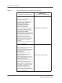
Table 4-1.
Catalyst Switch Events and Alarms (Continued)
Message in the Event Log
Alarm View
Probable Cause Message
CsEvFormat/Event011c0001
{d "%w- %d %m-, %Y - %T"} - A
Catalyst switch, {t} (name - {m}) has
reported the end of a TCP session. (event [{e}])
No probable cause message.
CsEvFormat/Event011c0003
{d "%w- %d %m-, %Y - %T"} - Module
{I 1} has been transitioned to the "Ok"
state. - (event [{e}])
No probable cause message.
CsEvFormat/Event011c0004
{d "%w- %d %m-, %Y - %T"} - Module
{I 1} has transitioned out of the "Ok"
state. - (event [{e}])
No probable cause message.
CsEvFormat/Event011c0005
{d "%w- %d %m-, %Y - %T"} - The
chassis' temp alarm is {T
CatChasAlrm 1}, the chassis' Minor
alarm is {T CatChasAlrm 2}, and the
chassis' Major alarm is {T
CatChasAlrm 3}. - (event [{e}])
9032208 E4
No probable cause message.
Event and Alarm Messages
4-3
Device Events and Alarms
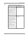
Table 4-1.
Catalyst Switch Events and Alarms (Continued)
Message in the Event Log
Alarm View
Probable Cause Message
CsEvFormat/Event011c0006
{d Ò%w- %d %m-, %Y - %TÓ} - Device
{m} of Type {t} reported A
conÞguration revision number error
notiÞcation which signiÞes that a
device has incremented its
vtpConÞgRevNumberErrors
counter. Generation of this
notiÞcation is suppresse
d if the vtpNotiÞcationsEnabled has
the value ÔfalseÕ. The device must
throttle the generation of consecutive
vtpConÞgRevNumberError
notiÞcations so that there is at least a
Þve-second gap between notiÞcation of
this type. When notiÞcation are
throttled, they are dropped, not
queued for sending at a future time.
(Note that ÔgeneratingÕ a notiÞcation
means sending to all conÞgured
recipients.
managementDomainConÞgRevNumb
er = { I 1 }. (Event [{e}]).
No probable cause message.
CsEvFormat/Event011c0007
{d Ò%w- %d %m-, %Y - %TÓ} - Device
{m} of Type {t} reported A
conÞguration digest error notiÞcation
which signiÞes that a device has
incremented its
vtpConÞgDigestErrors counter.
Generation of this notiÞcation is
suppressed if the vtp
NotiÞcationsEnabled has the value
ÔfalseÕ. The device must throttle the
generation of consecutive
vtpConÞgDigestError notiÞcations so
that there is at least a Þve-second gap
between notiÞcation of this type.
When notiÞcation are throttled, they
are dropped, not queued for sending
at a future time. (Note that
ÔgeneratingÕ a notiÞcation means
sending to all conÞgured recipients.)
managementDomainConÞgRevNumb
er = { I 1 }. (Event [{e}]).
Event and Alarm Messages
4-4
No probable cause message.
Cisco Catalyst 5000/5500 Hub
Management Module Guide
Device Events and Alarms
Table 4-1.
Catalyst Switch Events and Alarms (Continued)
Message in the Event Log
CsEvFormat/Event011c0008
Alarm View
Probable Cause Message
A vtpServerDisabled trap was
received from the device.
{d Ò%w- %d %m-, %Y - %TÓ} - Device
{m} of Type {t} reported A VTP Server
disabled notiÞcation. This trap is
generated when the local system is no
longer able to function as a VTP
Server because the number of deÞned
VLANs is greater than
vtpMaxVlanStorage. Generation of
this notiÞcation is suppressed if the
vtpNotiÞcationsEnabled has the value
ÔfalseÕ.
managementDomainConÞgRevNumb
er = { I 1 }, vtpMaxVlanStorage = {I 2}.
(Event [{e}]).
CsEvFormat/Event011c0009
A vtpMtuTooBig trap was received
from the device.
{d Ò%w- %d %m-, %Y - %TÓ} - Device
{m} of Type {t} reported A VTP MTU
tooBig notiÞcation. This trap is
generated when a VLANÕs MTU size
is larger than can be supported either
by one or more of its trunk ports (the
included vtpVlanState has the value
ÔmtuTooBigForTrunkÕ and the
included
vlanTrunkPortManagementDomain
is for the Þrst or only trunk port), or
by the device itself (vtpVlanState has
the value ÔmtuTooBigForDeviceÕ and
any instance of
vlanTrunkPortManagementDomain
is included.) Generation of this
notiÞcation is suppressed if the
vtpNotiÞcationsEnabled has the value
ÔfalseÕ.
vlanTrunkPortManagementDomain
= { I 1 }, vtpVlanState = { I 2 }. (Event
[{e}]).
9032208 E4
Event and Alarm Messages
4-5
Device Events and Alarms
Event and Alarm Messages
4-6
Cisco Catalyst 5000/5500 Hub
Management Module Guide
Chapter 5
Application View
What Is in This Chapter
This chapter describes the views and tables available for the following devicespeciÞc applications:
¥ Catalyst Stack Application (CATStackApp)
¥ Discovery Application (CiscoCDPApp)
¥ Ethernet Application (EthernetApp)
The Application view allows you to access increasingly detailed views of
network information for the applications supported by this device.
Common Applications
This device supports the following common applications described in the MIB
II Applications, Bridging Applications, and Miscellaneous
Applications references.
¥ MIB-II (SNMP2_Agent)
- IP (IP2_App)
- System (System2_App)
- ICMP (ICMP_App)
- UDP (UDP2_App)
- TCP (TCP2_App)
9032208 E4
5-1
Device Application View
¥ Bridging
- Gen Bridge App (Gen_Bridge_App)
- Spanning Tree (Span_Tree_App)
- Static (Static_App)
- Transparent (Transparent_App)
¥ FDDI Application (rfc1512App)
Device Application View
This view shows the common and device-speciÞc applications supported by
this device and provides access to application-speciÞc information.
See Chapter 1, Introduction, for information on Accessing SPECTRUM Views.
Figure 5-1 provides an example of an Application view in the icon mode.
Figure 5-2 provides an example of an Application view in the list mode.
To change the display mode, select View -> Mode -> List or Icon.
Application View
5-2
Cisco Catalyst 5000/5500 Hub
Management Module Guide
Device Application View
Figure 5-1.
Device Application View (Icon Mode)
Primary Landscape 0x00400000 - HubCat 500 of type HubCat 5000
*
File
View
Help?
Net Addr
Model Name
Sys Up Time
Contact
Manufacturer
Description
Device Type
Location
Prime-App
Serial Number
Model Name
HubCat5000
Gen Bridge App
MIB-II
CatalystStack
EthernetApp
FDDIApp
SNMP2_Agent
CATStackApp
EthernetApp
rfc1512App
Gen_Bridge_App
SNMP2_Agent
CATStackApp
EthernetIfApp
rfc1512App
Spanning Tree
ICMP
EthernetApp
SMT 5
ICMP_App
#1
GemFDDIS
ICMP_App
EthernetIfApp
GemFDDIS
System
EthernetApp
27.11 MAC
System2_App
#2
GemFDDIS
System2_App
EthernetIfApp
GemFDDIS
TCP
EthernetApp
Span_Tree_App
Static
Static_App
Static
Static_App
TCP2_App
#3
TCP2_App
EthernetIfApp
EthernetApp
#4
EthernetIfApp
9032208 E4
Application View
5-3
Device Application View
Figure 5-2.
Device Application View (List Mode)
Primary Landscape 0x00400000 - HubCat 5000 of type HubCat 5000
*
File
View
Help?
Net Addr
Model Name
Contact
Sys Up Time
Manufacturer
Description
Device Type
Location
Prime-App
Serial Number
Catalyst
GenBridgeApp
Span_Tree_App
Static_App
Transparnt_App
MIB-II
ICMP_App
IP2_App
System2_App
TCP2_App
UDP2_App
CATStackApp
CiscoCDPApp
Ethernet_App
FDDI_App
Application View
5-4
Cisco Catalyst 5000/5500 Hub
Management Module Guide
Device Application View
Catalyst Stack Application
Catalyst Stack Application
The Catalyst Stack application supported by the Cisco Catalyst Hub is
modeled in SPECTRUM with the CATStackApp Model Type. Table 5-1
describes each of the application-speciÞc Icon Subviews menu selections
available for the Catalyst Stack application.
Table 5-1.
Catalyst Stack Application-SpeciÞc Icon Subviews Menu Selections
Menu Selection
Description
ConÞguration
Opens the Catalyst Stack ConÞguration view (Page 3-4).
Bridge/Router
Opens the BRouter Information view (Page 5-5).
Community Strings
Opens the Community Strings View (Page 5-8).
FDDI Ring
Opens the FDDI Ring Table (Page 5-9).
Filter
Opens the Catalyst Filter Tables (Page 5-10).
Monitor
Opens the Monitor Information View (Page 5-13).
TFTP
Opens the Catalyst TFTP Information View (Page 5-14).
Trap Receiver
Opens the Catalyst Trap Receiver Table (Page 5-15).
VLan
Opens the Catalyst VLan Table (Page 5-16).
VLan Ports
Opens the VLan Ports Table (Page 5-16).
VLan_ConÞgure
Opens the Catalyst VLan Manager, (page 5-16) which
allows you to add or remove VLANs and change the VLAN
conÞguration of each port.
Model Information
Opens the Model Information view described in the
SPECTRUM Views reference.
BRouter Information
To access the BRouter Information view, do the following:
1. Within the Application view, highlight the Catalyst Stack Application
icon.
2. From the Icon Subviews menu, select Bridge/Router.
9032208 E4
Application View
5-5
Device Application View
This view provides the following information:
Enable Rip
Allows you to enable or disable the RIP protocol on the Catalyst Switch.
Enable IP Frag
Allows you to enable or disable IP Fragmentation on the Catalyst Switch.
Enable Spantree
Allows you to enable or disable the Spanning Tree protocol on the Catalyst
Switch.
Enable Giant Check
Allows you to enable or disable the Catalyst SwitchÕs ability to give special
handling to giant packets.
Enable Unreachables
Allows you to select whether the Catalyst Switch is able to send ICMP
unreachable messages.
Application View
5-6
Cisco Catalyst 5000/5500 Hub
Management Module Guide
Device Application View
CAM Aging Time
Displays the aging time for the CAM table.
CAM Mode
Allows you to select whether the CAM module is operating in Filtering Mode
or Forwarding Mode.
IPX SNAP To Ether
Allows you to select the default translation for IPX packets when bridging
from FDDI SNAP to Ethernet. Possible options are SNAP, EthernetII,
ISO8023, and RAW8023.
IPX 8022 To Ether
Allows you to select the default translation for IPX packets when bridging
from FDDI 802.2 to Ethernet. Possible options are SNAP, EthernetII,
ISO8023, and RAW8023.
IPX 8023RAW To FDDI
Allows you to select the default translation for IPX packets when bridging
from Ethernet 802.3 Raw to FDDI. Possible options are SNAP and ISO8022.
Ethernet Receive Max
Displays the maximum number of Ethernet receive buffers processed at one
time per port.
Ethernet Transmit Max
Displays the maximum number of Ethernet transmit buffers processed at one
time per port.
FDDI Receive Max
Displays the maximum number of FDDI receive buffers processed at one time
per port.
FDDI Transmit Max
Displays the maximum number of FDDI transmit buffers processed at one
time per port.
BRouter Ports
Allows you to access the Catalyst Stack BRouter Ports Table. Table 5-2
provides deÞnitions of the Þelds in the BRouter Ports Table.
9032208 E4
Application View
5-7
Device Application View
Community Strings
Table 5-2.
BRouter Ports Table Field DeÞnitions
Column
Heading
DeÞnition
Module
The unique integer identiÞer of the module where
this port is located. This number is the same as the
slot number in which the module is installed.
Port
The unique integer identiÞer of this port within its
module. This value is determined by the location of
the port on the module.
Route Group
The IP route group to which this port belongs.
IP Addr
The IP address of this port.
Net Mask
The subnet mask of this port.
Broadcast
The broadcast address of this port.
Bridge Group
The bridge group to which this port belongs.
Community Strings
This view lists the community strings and allows you to change the access
levels. When an SNMP message is received by the Catalyst Switch, the
messageÕs community string is compared with this table to determine the
access rights of the messageÕs sender.
To access this view, do the following:
1. Within the Application view, highlight the CATStackApp icon (icon mode)
or model type name (list mode).
2. From the Icon Subviews menu, select Community Strings.
Application View
5-8
Cisco Catalyst 5000/5500 Hub
Management Module Guide
Device Application View
FDDI Ring Table
Table 5-3 lists the possible Community String entries.
Table 5-3.
Community Strings View Access Levels
Access Level
Description
Read Only
Allows read privileges only.
Read Write
No write privileges to the
Community Strings Table only.
Read Write
Allows full read-write privileges.
FDDI Ring Table
This table lists the nodes in the FDDI ring(s) to which the device is attached.
Double-click a table entry to access an entry-speciÞc FDDI Ring table that
allows you to modify the information displayed in the table.
To access this table, do the following:
1. Within the Application view, highlight the CATStackApp icon (icon mode)
or model type name (list mode).
2. From the Icon Subviews menu, select FDDI Ring.
The FDDI Ring Table and its corresponding entry-speciÞc views provide the
following information:
SMT Index
Displays the SMT index number that identiÞes this ring.
Address
Displays the MAC address of this node in the ring.
Next Address
Displays the MAC address of the next node in the ring.
Information can be sorted, listed in ascending or descending order, printed, or
updated.
9032208 E4
Application View
5-9
Device Application View
Catalyst Filter Tables
Catalyst Filter Tables
The following series of views are accessed in the order listed and are described
below:
¥ MAC table/Vendor table
¥ Protocol table/Test table
¥ Port table
To access the views listed above, do the following:
1. Within the Application view, highlight the CATStackApp icon (icon mode)
or model type name (list mode).
2. From the Icon Subviews menu, select Filter.
3. Click the More button at the bottom of each view to access the next table
view in the series.
MAC Table
This area of the Catalyst Filter Tables contains a list of MAC Þlter entries.
Double-click a table entry to access an entry-speciÞc Filter MAC Table view.
This view allows you to modify the information presented in the table. The
MAC Table and its corresponding entry-speciÞc views provide the following
information:
Module
Displays the unique integer identiÞer of the module where this port is located.
This number is the same as the slot number in which the module is installed.
Port
Displays the unique integer identiÞer of this port within its module. This
value is determined by the location of the port on the module.
Address
Displays the MAC address to which the source and destination MAC
addresses of packets are compared. If the source or destination MAC address
equals this value, a match occurs. If ÒDenyÓ is speciÞed in the Type Þeld and a
match occurs, the packet is dropped. If at least one MAC address Þlter is
speciÞed with ÒPermitÓ and a match does not occur, the packet is dropped.
Type
Displays the type of action this Þlter will cause. Selecting ÒInvalidÓ removes
this Þlter from the table. Selecting ÒDenyÓ causes packets whose source or
destination address matches the MAC address speciÞed in the Address Þeld to
be dropped. Selecting ÒPermitÓ causes all packets whose source or destination
address does not match the address speciÞed in the Address Þeld to be
dropped.
Application View
5-10
Cisco Catalyst 5000/5500 Hub
Management Module Guide
Device Application View
Catalyst Filter Tables
Vendor Table
This area of the Filter Tables view contains a list of vendor ID Þlter entries.
Double-click a table entry to access an entry-speciÞc Filter Vendor Table view
that allows you to modify the information presented in the table. The Vendor
Table and its corresponding entry-speciÞc views provide the following
information:
Module
Displays the unique integer identiÞer of the module where this port is located.
This number is the same as the slot number in which the module is installed.
Port
Displays the unique integer identiÞer of this port within its module. This
value is determined by the location of the port on the module.
ID
Displays the vendor ID portion of a MAC address. If the source or destination
address has the same vendor ID, a match occurs. If ÒDenyÓ is speciÞed in the
Type Þeld and a match occurs, the packet is dropped. If at least one vendor ID
Þlter is speciÞed with ÒPermitÓ and a match does not occur, the packet is
dropped.
Type
Displays the type of action this Þlter will cause. Selecting ÒInvalidÓ removes
this Þlter from the table. Selecting ÒDenyÓ causes packets whose source or
destination vendor ID matches the vendor ID speciÞed in the ID Þeld to be
dropped. Selecting ÒPermitÓ causes all packets whose vendor ID does not
match the ID speciÞed in the ID Þeld to be dropped.
Protocol Table
The Protocol Table contains a list of protocol Þlter entries. Double-click a table
entry to access an entry-speciÞc Filter Protocol Table view that allows you to
modify the information presented in the table. The Protocol Table and its
corresponding entry-speciÞc views provide the following information:
Module
Displays the unique integer identiÞer of the module where this port is located.
This number is the same as the slot number in which the module is installed.
Port
Displays the unique integer identiÞer of this port within its module. This
value is determined by the location of the port on the module.
Value
Displays the 16-bit protocol value. If the packetÕs Type Þeld or the packetÕs
DSAP/SSAP Þeld is equal to this value, a match occurs. If Deny is speciÞed
and a match occurs, the packet is dropped. If at least one protocol type Þlter is
speciÞed with Permit and a match does not occur, the packet is dropped.
9032208 E4
Application View
5-11
Device Application View
Catalyst Filter Tables
Type
Displays the type of action this Þlter will cause. Selecting Invalid removes this
Þlter from the table. Selecting Deny causes packets whose Type Þeld or DSAP/
SSAP Þeld matches the value speciÞed in the Value Þeld to be dropped.
Selecting Permit causes all packets whose Type Þeld or DSAP/SSAP Þeld does
not match the value speciÞed in the Value Þeld to be dropped.
Test Table
The Test Table contains a list of test Þlter entries. Double-click a table entry to
access an entry-speciÞc Filter Test Table view that allows you to modify the
information presented in the table. The Test Table and its corresponding
entry-speciÞc views provide the following information:
Module
Displays the unique integer identiÞer of the module where this port is located.
This number is the same as the slot number in which the module is installed.
Port
Displays the unique integer identiÞer of this port within its module. This
value is determined by the location of the port on the module.
Index
Displays an index value that uniquely identiÞes a test for a particular module
and port (Test Table only).
Type
Validates or shows a new module, port, or test index (when one exists).
Offset
Displays a byte offset into a packet. Must be a 32-bit word aligned offset, i.e.,
0, 4, 8, etc.
Value
A 32-bit value to be compared against the packet location speciÞed in the
Offset Þeld (Entry-speciÞc view only).
Mask
An internet mask the server uses to distinguish internet address that can be
reached directly from those that must be reached via an IP gateway.
Port Table
The Port Table contains a list of port Þlter entries. Double-click a table entry
to access an entry-speciÞc Filter Port Table view that allows you to modify the
information presented in the table. The Port Table and its corresponding
entry-speciÞc views provide the following information:
Application View
5-12
Cisco Catalyst 5000/5500 Hub
Management Module Guide
Device Application View
Monitor Information View
Module
Displays the unique integer identiÞer of the module where this port is located.
This number is the same as the slot number in which the module is installed.
Port
Displays the unique integer identiÞer of this port within its module. This
value is determined by the location of the port on the module.
Throttle
Displays the maximum number of broadcast packets per second allowed on
this port. Packets in excess of this limit are dropped. A value of zero indicates
that unlimited broadcast packets are allowed.
Monitor Information View
To access the Monitor Information view, do the following:
1. Within the Application view, highlight the Catalyst Stack Application icon.
2. From the Icon Subviews menu, select Monitor.
This view provides the following information:
Source Module
Displays the unique integer identiÞer of the module where the monitoring
source port is located. A value of zero indicates that the source port is really a
source Virtual LAN number.
Source Port
Displays the unique integer identiÞer of the monitoring source port within its
module or the monitoring source virtual LAN.
Destination Module
Displays the unique integer identiÞer of the module where the monitoring
destination port is located.
Destination Port
Displays the unique integer identiÞer of the monitoring destination port
within its module.
Direction
Allows you to select the type of packets that will be monitored at the source
port. Possible selections are: Transmit, Receive, and TransmitReceive.
Enable
Indicates whether port monitoring is in progress. Choosing Enabled begins
port monitoring. Choosing disabled ends port monitoring.
9032208 E4
Application View
5-13
Device Application View
Catalyst TFTP Information View
Catalyst TFTP Information View
This view allows you to conÞgure and initiate Þle transfers to and from the
device. To access the Catalyst TFTP Information view, do the following:
1. Within the Application view, highlight the CATStackApp icon (icon mode)
or model type name (list mode).
2. From the Icon Subviews menu, select TFTP.
The Catalyst TFTP Information view provides the following information:
Host
Displays the operator-deÞned name of the source or destination host for this
Þle transfer.
File
Displays the operator-deÞned name of the Þle for this Þle transfer.
Module
Displays the operator-deÞned number of the module to or from which code or
conÞguration information is being transferred.
Action
This button allows you to select the type of transfer to be carried out and to
initiate the transfer. Possible actions are listed in Table 5-4.
Table 5-4.
TFTP Transfer Action Types
Action
Application View
5-14
DeÞnition
Other
Default value - None of the following.
DownLoadConÞg
Receive conÞguration information from the selected host and Þle.
UpLoadConÞg
Send conÞguration information to the selected host and Þle.
DownLoadSw
Receive a software image from the selected host and Þle.
UpLoadSw
Send a software image to the selected host and Þle.
DownLoadFw
Receive a Þrmware image from the selected host and Þle.
UpLoadFw
Send a Þrmware image to the selected host and Þle.
Cisco Catalyst 5000/5500 Hub
Management Module Guide
Device Application View
Catalyst Trap Receiver Table
Catalyst Trap Receiver Table
This table lists the addresses of Network Management Stations that should
receive trap messages from the Catalyst Stack Application. Double-click a
table entry to access the entry-speciÞc Catalyst Trap Receiver table, which
allows you to change the items displayed in the table.
To access the Catalyst Trap Receiver table, do the following:
1. Within the Application view, highlight the CATStackApp icon (icon mode)
or model type name (list mode).
2. From the Icon Subviews menu, select Trap Receiver.
The Catalyst Trap Receiver table provides the following information:
The Trap Receiver Table and its corresponding entry-speciÞc views provide
the following information:
Type
Displays the status of this entry. Setting this value to ÒInvalidÓ removes the
corresponding entry from the Trap Receiver Table. To add a new entry to the
Trap Receiver Table, set this value to ÒValidÓ for an IP address that is not
already in the table.
Addr
Displays the IP address of the Network Management Station receiving the
traps.
Community
Displays the community string used for trap messages sent to this trap
receiver.
Catalyst VLan Table
The Catalyst VLan table provides a list of Virtual LAN entries, which are
determined by the LANs within the system. To access the Catalyst VLan
table, do the following:
1. Within the Application view, highlight the CATStackApp icon (icon mode)
or model type name (list mode).
2. From the Icon Subviews menu, select VLan.
The VLan table view provides the following information:
VLan Index
IdentiÞes the Virtual LAN associated with this module port.
Spanning Tree
Indicates whether the Spanning Tree protocol is enabled for this Virtual LAN.
Possible values are Enabled and Disabled.
9032208 E4
Application View
5-15
Device Application View
VLan Ports Table
VLan Ports Table
The Catalyst VLan Ports Table provides a list of Virtual LAN port entries,
which are determined by the number of modules in the chassis and by the port
in each module. To access the Catalyst VLan Ports table do the following:
1. Within the Application view, highlight the CATStackApp icon (icon mode)
or model type name (list mode).
2. From the Icon Subviews menu, select VLan Ports.
The VLan view provides the following information:
Module
Displays the index value that uniquely identiÞes this port within this module.
Port
Displays the port number within the identiÞed module.
Vlan
Displays the Virtual LAN to which this port is attached.
Switch Level
Displays the switch priority level the port uses to access the switching media.
If the port is functioning correctly, the ÒNormalÓ value appears.
Catalyst VLan Manager
This view provides a graphical display of the deviceÕs module and port
conÞguration, and indicates the vlan to which each port is assigned. This view
also allows you to perform the following functions:
¥
¥
¥
¥
Selecting a VLAN
Adding a VLAN
Changing a PortÕs VLAN
Removing a VLAN
To Access the Vlan ConÞguration Manager view, do the following:
1. Within the Application view, highlight the CATStackApp icon.
2. From the Icon Subviews menu, select VLan_ConÞgure.
Application View
5-16
Cisco Catalyst 5000/5500 Hub
Management Module Guide
Device Application View
Catalyst VLan Manager
Selecting a VLan
Within the VLAN panel (Figure 5-3 ) of the Catalyst VLan Manager view, click
on the VLAN number to display or assign ports. The VLAN number icon and
the ports assigned to that VLAN will be highlighted.
Figure 5-3.
VLAN Panel
VLAN Number Icon
1
44 ports
2
20 ports
3
24 ports
Adding a VLAN
Within the VLAN panel, enter the number of the VLAN you would like to add.
Click the ÒAddÓ button. A button representing the new VLAN will appear in
the VLAN panel.
9032208 E4
Application View
5-17
Device Application View
Discovery Application
Figure 5-4.
Add/Remove Buttons
Add
VLAN:
Remove
3
Changing a PortÕs VLAN
To select a VLAN to add a port to, highlight the VLAN number icon in the
VLAN panel. Double click on the port icon which you would like to add to the
VLAN. The port icon will be highlighted to indicate the change. The port
counts, next to the VLAN icons, should accurately reßect the number of ports
assigned to each VLAN.
Removing a VLAN
To remove a VLAN, make sure there are no ports assigned to the VLAN.
Highlight that VLANÕs number icon. Click the ÒRemoveÓ button. The VLAN
will be removed from the VLAN panel.
Discovery Application
This section describes the Discovery Application supported by the cisco
Catalyst Hub. The model type name for this application is CiscoCDPApp.
Table 5-5 describes each of the application-speciÞc Icon Subviews menu
selections available for the Discovery Application.
Table 5-5.
Catalyst Stack Application-SpeciÞc Icon Subviews Menu Selections
Menu Selection
Description
Cache
Opens the Discovery Cache Table view, described later in
this chapter.
Interfaces
Opens the Interface Discovery Status Table view, described
later in this chapter.
Model Information View Opens the Model Information view described in the
SPECTRUM Views reference.
Application View
5-18
Cisco Catalyst 5000/5500 Hub
Management Module Guide
Device Application View
Discovery Cache Table View
Discovery Cache Table View
This view provides the information recieved by the Cisco Discovery Protocol
(CDP). It provides the following information:
Type
Displays the type of address contained in the corresponding Address Þeld
described below.
Address
Displays the network layer of the deviceÕs SNMP-agent as reported in the
most recent CDP message.
Device ID
Displays the Device-ID. A zero indicates no Device-ID was reported.
Device Port
Displays the Port-ID. A zero indicates no Port-ID was reported.
Platform
Displays the devices hardware platform.
Capabilities
Displays the devices functional capabilities.
Interface Discovery Status Table
This table contains the status of Cisco Discovery Protocol on the device's
interfaces. It provides the following information:
Discovery
Displays information about the type of devices in the network, conÞguration
information about the links connecting those devices, and the number of
interfaces within each device.
Group
Displays the group number of the repeater port which corresponds to this
interface.
Port
Displays the port number of the repeater port which corresponds to this
interface.
Interval
Displays the interval at which the CDP messages are to be generated on this
interface. The default value is 60 seconds.
9032208 E4
Application View
5-19
Device Application View
Ethernet Application
Ethernet Application
This application provides access to the application-speciÞc Detail view.
To access the Detail view, select Detail from the Icon Subview menu. This
view provides access to three pie charts with performance statistics. For more
information about the frame or transmit error performance statistics, refer to
How to Manage Your Network with SPECTRUM.
Application View
5-20
Cisco Catalyst 5000/5500 Hub
Management Module Guide
Index
Symbols
#1 Status 3-8
#1 Test Results 3-8
#1 Type 3-8
#2 Status 3-8
#2 Test Results 3-8
#2 Type 3-8
(rfc1512Ap 5-2
Numerics
1 Dual Phy Multi Mode OC-3 ATM 3-7
1 Dual Phy Single Mode OC-3 ATM 3-7
1 Dual Phy UTP OC-3 ATM 3-7
1 Port Multi Mode OC-3 ATM 3-7
1 Port Single Mode OC-3 ATM 3-7
1 Port UTP OC-3 ATM 3-7
12 Port 10/100BaseTX 3-7
12 Port 100BaseF 3-7
12 Port 100BaseFX Multi Mode 3-7
12 Port 100BaseTX 3-6
12 port 100BaseTX 3-6
12 Port 10BaseFL 3-6
24 Port 10/100BaseTX 3-7
24 Port 10BaseT 3-6
24 Port 3 Segment 100BaseTX 3-7
48 Port 10BaseT 3-7
48 Port 4 Segment 10BaseT 3-7
6 Port Single Mode 6 Port Multi Mode
100BaseFX 3-7
A
Accessing SPECTRUM Views 1-3
Action Button 2-14
Additional Status 2-16, 3-11
Additional Status Value 2-16
Addr 5-15
Address 5-9, 5-10, 5-19
Network 2-6
address
MAC 2-4, 3-2, 3-3
Admin. Status 3-3
Administrative Status 2-16, 3-3
Administrative Status Label 2-4
Alarm Messages 4-1
Alarms 3-9
Application View 5-1
Tables 5-5
Application Views
Catalyst Stack 5-5
Apply button 2-9
ARP Aging Time 3-6
Attach Type 3-5
Attribute
Selected 2-7
B
Backplane 3-7
Bandwidth 3-2, 3-4
Baud Rate 3-4
Bridge
Group 5-8
Bridging 5-2
Broadcast 3-4, 5-8
broadcast packets per second 5-13
BRouter
Information 5-5
Ports Button 5-7
C
CAM
Aging Time 5-7
Mode Button 5-7
CAM table 5-7
Capabilities 5-19
Catalyst
Events and Alarms 4-1
Catalyst Stack
Application Views 5-5
BRouter Information 5-5
BRouter Ports Table 5-7
Supported Model Type 5-5
9032208 E4
1
Catalyst Stack Application 5-1
Catalyst Stack ConÞguration View 3-1
Catalyst Stack Ports Table 3-10
Sort On 3-12
Catalyst Stack System ConÞguration
View 3-4
Catalyst VLan Manager 5-16
Adding a VLAN 5-17
Changing a PortÕs VLAN 5-18
Discovery Application 5-18
Removing a VLAN 5-18
Selecting a VLan 5-17
CATStackApp 5-1
Chassis 3-6
Button 3-6
Information View 3-6
Chassis Device View 2-10
Cisco Catalyst Hub 1-1
CiscoCDPApp 5-1
Clear
MAC
Button 3-4
Time 3-4
Port Time 3-5
Ports Button 3-5
Close button 2-9
Common Applications
Ch 5 5-1
Community 5-15
Strings Table 5-8
Community Strings Table 5-9
ConÞguration 3-4
ConÞguration View 3-1
Contact
Status 3-1
D
Default button 2-9
Description 3-2
Destination
Module 5-13
Port 5-13
Device
Name 3-1
Device Application View 5-2
Device ConÞguration Information 3-1
Device ConÞguration View 3-1
Device ID 5-19
Device Port 5-19
Index
2
Device View 2-1
Banner 2-12
Chassis 2-10
Interface 2-1, 2-2
Direction Button 5-13
Discovery 5-19
Discovery Cache Table View 5-19
Documentation xii
documentation
conventions xii
organization xi
DownLoadConÞg 5-14
DownLoadFw 5-14
DownLoadSw 5-14
DSAP/SSAP Þeld 5-11
Dual Attach CDDI 3-7
Dual Attach Multi Mode FDDI 3-7
Dual Attach Single Mode FDDI 3-7
DualAttach 3-5
E
Enable
Button 5-13
Giant Check Button 5-6
IP Frag Button 5-6
Modem Button 3-5
Redirects Button 3-5
Rip Button 5-6
Rmon Button 3-5
Spantree Button 5-6
Unreachables Button 5-6
Environmental Device View 2-1
Ethernet
Port
Logical
Access Label Detail 2-1
Receive Max 5-7
Transmit Max 5-7
Ethernet 802.3 Raw 5-7
Ethernet Application 5-1
EthernetApp 5-1
Event Messages 4-1
F
Fan 3-8
FDDI
Application Views 5-20
Cisco Catalyst 5000/5500 Hub
Management Module Guide
Port
Logical
Access Label Detail 2-1
Receive Max 5-7
Ring Table 5-9
Transmit Max 5-7
FDDI Application 5-2
FDDI Ring Table 5-9
FDDI transmit buffers 5-7
File 5-14
Filter Tables 5-10
Filtering Mode 5-7
Find 2-6
Firmware 2-14
Forwarding Mode 5-7
G
Gauge
Control Panel 2-6
gauge
buttons 2-9
label 2-5
mode 2-9
selected attribute 2-9
type 2-9
Gen Bridge App 5-2
Gen_Bridge_Ap 5-2
Generic
Views 3-1
giant packets 5-6
Group 5-19
H
Hardware 2-14
Host 5-14
I
ICMP unreachable messages 5-6
ICMP_App 5-1
ID 5-11
IF
Address Translation Table 3-2
IF ConÞguration 3-3
IF ConÞguration View 3-3
Index 2-13, 2-16, 3-2, 3-9, 3-10, 5-12
Insert Mode Button 3-5
9032208 E4
Interface
Description 2-6
Device View 2-1
Icon
Logical 2-6
Panel 2-12
Options Panel 2-6
interface
icon, Device View 2-3, 2-11
type 2-4
Interface ConÞguration Table 3-2
Interface Device View 2-1, 2-2
Interface Discovery Status Table 5-19
Interface Icon, Device View
administrative status label 2-4
gauge label 2-5
illustration 2-3
interface number label 2-4
interface type label 2-4
MAC address label 2-4
network information label 2-5
Interface Index 2-4
Interface Number Label 2-4
Interface Options Panel 2-9
Interval 5-19
Introduction 1-1
IP
Addr 5-8
IP Application 5-1
IP Fragmentation 5-6
IP2_App 5-1
IPX
8022 To Ether 5-7
8023RAW To FDDI 5-7
SNAP To Ether 5-7
IPX packets 5-7
ISO8023 5-7
K
Keep Settings button 2-9
L
Last Change 3-3
M
MAC
Index
3
Table 5-10
MAC Address Label 2-4
MAC Þlter entries 5-10
Major 3-9
Mask 5-12
Network 2-6
Mgmt
Type 3-4
MIB-II 5-1
Minor 3-9
Model 3-6, 3-10
Module 2-13, 2-16, 3-10, 5-8, 5-10, 5-11, 5-12,
5-13, 5-14
Module Status Label 2-13
Module Table View 2-13
Modules
Button 3-6
Monitor Information View 5-13
P
Packet Size 3-3, 3-4
Permit 5-10
Physical Address 2-4, 3-2, 3-3
Platform 5-19
Port 5-8, 5-10, 5-11, 5-12, 5-13, 5-19
Table
Catalyst Stack 5-12
Port Icon 2-15
Port Table View 2-16
Ports 3-10
Button 3-6
Table 3-9
Power Supplies 3-8
Protocol
Table 5-11
Q
N
Name 2-13, 2-16, 3-9, 3-10
Network 2-6
Net
Mask 3-4, 5-8
Network
Information 2-6
Network Address 2-5
Network Information Label 2-5
Network Name/Address 3-3
Next
Address 5-9
Notice i
NullAttach 3-5
Num Ports 2-14
Number
Interfaces 3-2
Slots 3-8
O
Offset 5-12
Operation Status 3-2, 3-3
Operational Status 2-16
Order 3-10, 3-12
Other 3-5, 5-14
Other Related Documentation xiii
Index
4
Queue Length 3-3, 3-4
R
RAW8023 5-7
ReconÞgure 3-2
Related Reading xii, xiii
Reset Button 3-5
Reset button 2-9
Restricted Rights Notice ii
RIP protocol 5-6
Route
Group 5-8
S
Security
Port
Lock/Unlock 2-1
Selected Attribute 2-8
Serial Nbr 2-13, 3-9
SingleAttach 3-5
SMT
Index 5-9
SNAP 5-7
SNMP2_Agent 5-1
Software 2-14
Sort On 3-10
Source
Cisco Catalyst 5000/5500 Hub
Management Module Guide
Module 5-13
Port 5-13
source Virtual LAN 5-13
Span_Tree_App 5-2
Spanning Tree protocol 5-6
SPECTRUM Support 1-1, 1-2
SPECTRUM Views Roadmap 1-5
Speed 2-16
Static 5-2
Static_Ap 5-2
Status 2-13, 2-16, 3-8, 3-11
Sub Type 2-14
Supervisor Module II, 2 100BaseFX Multi
Mode 3-7
Supervisor Module II, 2 100BaseFX Single
Mode 3-7
Supervisor Module II, 2 100BaseTX 3-7
Supervisor Module, 2 100BaseFX Multi
Mode 3-7
Supervisor Module, 2 100BaseFX Single
Mode 3-7
Supervisor Module, 2 100BaseTX 3-6
System
Type 3-6
System2_App 5-1
T
Temp 3-9
Test Result 3-8
Test Results 2-14
Test Table 5-12
TFTP Information View 5-14
Throttle 5-13
Trademarks i
TrafÞc 3-5
Transparent 5-2
Transparent_Ap 5-2
trap messages 5-15
Trap Receiver Table 5-15
Type 2-13, 2-16, 3-2, 3-9, 3-10, 5-10, 5-11, 512, 5-15, 5-19
U
UpLoadConÞg 5-14
UpLoadFw 5-14
UpLoadSw 5-14
V
Value 5-11, 5-12
vendor ID Þlter 5-11
Vendor Table 5-11
Versions 2-14
Virtual LAN 5-15
Virus Disclaimer i
VLAN Router 3-7
W
What Is in This Chapter
Ch 1 1-1
Ch 2 2-1
Ch 3 3-1
Ch 5 5-1
wsc1000 3-6
wsc1001 3-6, 3-7
wsc1100 3-7
wsc1200 3-7
wsx5005 3-7
wsx5006 3-7
wsx5011 3-6
wsx5012 3-7
wsx5020 3-7
wsx5114 3-7
wsx5156 3-7
wsx5157 3-7
wsx5158 3-7
wsx5201 3-7
wsx5203 3-7
wsx5213 3-7
wsx5213a 3-7
wsx5223 3-7
wsx5224 3-7
wsx5302 3-7
wsx5505 3-7
wsx5506 3-7
wsx5509 3-7
UDP
Application 5-1
UDP2_App 5-1
unique integer identiÞer 5-10
9032208 E4
Index
5
Index
6
Cisco Catalyst 5000/5500 Hub
Management Module Guide