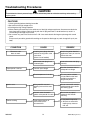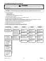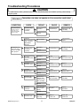
1
Service
This manual is to be used by qualified appliance
technicians only. Maytag does not assume any
responsibility for property damage or personal
injury for improper service procedures done by an
unqualified person.
2001/2002
Convection
Domestic
Microwave Ovens
This Base Manual covers general information
©2005 Maytag Services
This manual includes, but is
not limited to the following:
ACM1580AB
ACM1580AC
ACM1580AS
ACM1580AW
JMC9158AAB
JMC9158AAQ
JMC9158AAS
JMC9158AAW
16026267
Replaces 16021669
June 2005
Important Information
Pride and workmanship go into every product to provide our customers with quality products. It is possible, however,
that during its lifetime a product may require service. Products should be serviced only by a qualified service
technician who is familiar with the safety procedures required in the repair and who is equipped with the proper tools,
parts, testing instruments and the appropriate service manual. REVIEW ALL SERVICE INFORMATION IN THE
APPROPRIATE SERVICE MANUAL BEFORE BEGINNING REPAIRS.
Important Notices for Consumers and Servicers
!
WARNING
To avoid risk of serious injury or death, repairs should not be attempted by an unauthorized personal, dangerous
conditions (such as exposure to electrical shock) may result.
!
CAUTION
Maytag will not be responsible for any injury or property damage from improper service procedures. If performing
service on your own product, assume responsibility for any personal injury or property damage which may result.
To locate an authorized servicer, please consult your telephone book or the dealer from whom you purchased this
product. For further assistance, please contact:
Customer Service Support Center
CAIR Center
Web Site
Telephone Number
WWW.AMANA.COM ................................................ 1-800-843-0304
WWW.JENNAIR.COM ............................................. 1-800-536-6247
WWW.MAYTAG.COM ............................................. 1-800-688-9900
CAIR Center in Canada .......................................... 1-800-688-2002
Amana Canada Product ........................................... 1-866-587-2002
Recognize Safety Symbols, Words, and Labels
! DANGER
DANGER—Immediate hazards which WILL result in severe personal injury or death.
!
WARNING
WARNING—Hazards or unsafe practices which COULD result in severe personal injury or death.
!
CAUTION
CAUTION—Hazards or unsafe practices which COULD result in minor personal injury or product or property
damage.
16026267
2
©2005 Maytag Services
Table of Contents
Wiring Diagram and Schematic
Series 10 ............................................................. 23
Series 11 ............................................................. 24
Appendix A
Owner's Manual ................................................. A-2
Important Information ................................................. 2
Important Safety Instructions ...................................... 4
Specifications ............................................................. 7
Component Specifications .......................................... 8
Microwave Energy Leakage Test
Equipment ............................................................ 11
Procedure for Measuring Radiation Leakage ...... 11
Measurement with the Outer Case Removed ........ 11
Measurement with a Fully Assembled Oven ......... 11
Record Keeping and Notification
After Measurement ............................................... 11
Troubleshooting Procedures ................................ 12-17
Disassembly Procedures
Outer Case Removal ............................................ 18
Control Panel Assembly and
Printed Circuit Board Removal ............................. 18
Door Removal ...................................................... 18
Door Disassembly ................................................ 18
Lamp Socket Removal ......................................... 19
Magnetron Removal ............................................. 19
Cooling Fan Removal ........................................... 19
High Voltage Capacitor and Diode Removal ........ 19
High Voltage Transformer Removal ...................... 19
Turntable Motor Removal ...................................... 19
Convection Motor Removal ................................... 20
Heater Element Removal ...................................... 20
Thermistor Removal ............................................. 20
Sensor Removal ................................................... 20
Primary Interlock Switch Removal ....................... 20
Secondary Interlock, Monitor, and
Oven Lamp Switch Removal ................................. 21
Noise Filter Removal ............................................ 22
©2005 Maytag Services
3
16026267
Important Safety Instructions
Recognize this symbol as a SAFETY message
Recognize this symbol as a HOT SURFACE warning
!
WARNING
When using electrical equipment, basic safety precautions should be followed to avoid the risk of burns, electrical
shock, fire or injury to persons.
1. READ all instructions before using the appliance.
2. READ AND FOLLOW the specific
“PRECAUTIONS TO AVOID POSSIBLE
EXPOSURE TO EXCESSIVE MICROWAVE
ENERGY."
3. This appliance MUST BE GROUNDED. Connect
only to properly grounded outlet. See
“GROUNDING INSTRUCTIONS."
4. Install or locate this appliance ONLY in
accordance with the provided installation
instructions.
5. Some products such as whole eggs and sealed
containers for example, closed glass jars may
explode and SHOULD NOT be HEATED in this
oven.
6. Use this appliance ONLY for its intended use as
described in this manual. Do not use corrosive
chemicals or vapors in this appliance. This type of
oven is specifically designed to heat or cook.
It is not designed for industrial or laboratory use.
7. As with any appliance, CLOSE SUPERVISION is
necessary when used by CHILDREN.
8. DO NOT operate this appliance if it has a
damaged cord or plug, if it is not working properly,
or if it has been damaged or dropped.
9. This appliance should be serviced ONLY by
qualified service personnel. Contact nearest
authorized service facility for examination, repair
or adjustment.
10. DO NOT cover or block any openings on the
appliance.
11. DO NOT store this appliance outdoors. DO NOT
use this product near water, for example, near a
kitchen sink, in a wet basement, or near a
swimming pool, etc.
12. DO NOT immerse cord or plug in water.
13. Keep cord AWAY from HEATED surfaces.
14. DO NOT let cord hang over edge of table or
counter.
15. See door cleaning instructions.
16. DO NOT operate any heating or cooking appliance
beneath this appliance.
17. DO NOT mount unit over or near any portion of a
heating or cooking appliance.
18. DO NOT mount over a sink.
19. DO NOT store anything directly on top of the
appliance surface when the appliance is in
operation.
20. Oversized foods or oversized utensils should not
be inserted in a microwave/convection oven as
they may create a fire or risk of electrical shock.
21. DO NOT clean with metal scouring pads. Pieces
can burn off the pad and touch electrical parts
involving risk of electrical shock.
22. DO NOT use paper products when appliance is
operated in convection or combination mode.
23. DO NOT store any materials, other than
manufacturer's recommended accessories, in this
appliance when not in use.
24. DO NOT cover racks or any other part of the oven
with metal foil. Covered racks will cause
overheating of the oven.
SAVE THESE INSTRUCTIONS
16026267
4
©2005 Maytag Services
Important Safety Instructions
!
CAUTION
11. Use only popcorn in packages designed and
labeled for microwave use. Pop according to
package directions, beginning with the
minimum amount of time recommended.
Use caution when handling hot popcorn bag.
12. Microwave convenience foods are often
packaged in specially designed packaging.
Special plates, lids, containers, or other
unique packaging materials may be used.
Susceptor packing material (a thin, metalized
plastic film) is frequently used to help brown
and make crisp foods such as microwave pizzas,
French fries, or fish sticks. Be sure to follow
food package instructions carefully. Contact
convenience food manufacturer with
questions concerning these products. Amana
does not endorse any brand of microwave
convenience foods, or any type of microwave
food packaging.
13. Do not operate microwave oven empty. This
could damage the oven.
14. Do not use regular cooking thermometers in
oven. Most cooking thermometers contain
mercury and may cause “arcing”, malfunction,
and/or damage to oven.
15. Metal or ceramic accessories which are
designed to absorb microwave energy to
provide heat should be used with caution. Test
device before use. Read and follow
manufacturer's instructions provided with the
accessory. Contact accessory manufacturer
with questions concerning these accessories.
Amana does not endorse any brand of
accessory.
16. Do not use paper products not intended for
cooking when oven is operated in convection or
combination mode.
17. Pierce or open plastic bags (and other airtight
containers) before heating in microwave oven.
This allows steam to escape during cooking.
18. Containers may become hot and pot holders may
be needed.
19. Closely supervise any use by children. Make
sure they can read instructions and reach
controls. Never allow them to lean or swing on
oven door.
To avoid personal injury or property damage observe
the following:
1. Always press STOP/RESET before programming
oven.
2. Do not deep fat fry in oven. Fat could overheat
and be hazardous to handle.
3. Do not cook or reheat eggs in shell or with an
unbroken yolk. Pressure may build up and
erupt. Pierce yolk with a fork or knife before
cooking. Do not reheat previously cooked eggs
in the microwave oven unless finely chopped or
scrambled.
4. Pierce skin of potatoes, tomatoes, or other foods
with a "skin" before cooking in microwave oven.
Piercing skin allows steam to escape during
cooking.
5. Do not home can in microwave oven. Home
canning is generally done with metal lids. Since
metal lids reflect heat, product may not be heated
uniformly to 212°F or above. Food could
deteriorate. USDA extension specialists do not
recommend home canning in microwave ovens.
6. Remove excess fat from meats and poultry to
prevent splattering.
7. Do not heat baby bottles in microwave oven.
8. Briskly stir or pour liquids before heating to
prevent spontaneous boiling or eruption. Do
not overheat. If air is not mixed into a liquid,
liquid can erupt in oven or after removal from
oven.
9. All uncooked foods should be heated to a final
internal temperature of at least 165°F. Some
foods require higher temperatures. These
recommended temperatures kill most food borne,
disease causing organisms. Some common
visual signs that indicate the cooking temperature
has been reached:
• Food steams throughout, not just around
edges.
• Center bottom of dish is very hot to the
touch.
10. If using a microwave popcorn popper, use
according to manufacturer's instructions. Do not
continue to heat after popping has stopped.
Popcorn will scorch or burn. Do not leave oven
unattended.
SAVE THESE INSTRUCTIONS
©2005 Maytag Services
5
16026267
Important Safety Instructions
!
PRECAUTIONS TO
AVOID
POSSIBLE
EXPOSURE TO
EXCESSIVE
MICROWAVE ENERGY
CAUTION
To reduce the risk of fire in the oven cavity:
a. DO NOT overcook food. Carefully attend
appliance if paper, plastic, or other combustible
materials are placed inside the oven to facilitate
cooking.
b. Remove wire twist-ties from paper or plastic bags
before placing bag in oven.
c. If materials inside the oven should ignite, keep
oven door closed, turn oven off, and disconnect
the power cord, or shut off power at the fuse or
circuit breaker panel. IF THE DOOR IS OPENED
THE FIRE MAY SPREAD!
d. DO NOT use the cavity for storage purposes. DO
NOT leave paper products, cooking utensils, or
food in the cavity when not in use.
!
a. DO NOT attempt to operate this oven with the
door open since open-door operation can result
in harmful exposure to microwave energy. It is
important not to defeat or tamper with the safety
interlocks.
b. DO NOT place any object between the oven front
face and the door or allow soil or cleaner residue
to accumulate on sealing surfaces.
c. DO NOT operate the oven if it is damaged. It is
particularly important that the oven door close
properly and that there is no damage to the: (1)
door (bent), (2) hinges and latches (broken or
loosened), (3) door seals and sealing surfaces.
d. The oven should NOT be adjusted or repaired by
anyone except properly qualified service
personnel.
CAUTION
To avoid burns use utensils or protective clothing, like
pan grips or dry oven mitts. Racks, utensils, and oven
surfaces can become hot during or after use.
SAVE THESE INSTRUCTIONS
16026267
6
©2005 Maytag Services
Specifications
Models
Power Source
Voltage AC
Amperage (single unit)
Frequency
Single phase, 3 wire grounded
Receptacle
Plug
Power Output
Nominal microwave energy (IEC705)
Operating frequency
Power Consumption
Cook condition microwave
Convection
Combination
Dimensions
Cabinet
Width
Height
Depth
Oven Interior
Width
Height
Depth
Weight
Crated
Uncrated
©2005 Maytag Services
7
AMC1580A*
JMC9158A*
120 VAC
30 A
60 Hz
X
6-20R
6-20P
120 VAC
30 A
60 Hz
X
6-20R
6-20P
1000 Watts
2450 MHz
1000 Watts
2450 MHz
1500 Watts
1500 Watts
1500 Watts
1500 Watts
1500 Watts
1500 Watts
22 5/8"
14 7/8"
20"
22 5/8"
14 7/8"
20"
15 1/4"
10 7/8"
15 1/4"
15 1/4"
10 7/8"
15 1/4"
59 lbs.
52 lbs.
59 lbs.
52 lbs.
16026267
Component Specifications
!
CAUTION
To avoid electrical shock, personal injury, or death, disconnect power to unit and discharge capacitor before
servicing, unless testing requires power.
Illustration
Secondary
terminal
Component
High voltage
transformer
Filament
winding
Primary
terminals
Testing
Disconnect wires from terminals.
Measure for continuity of following
terminals:
Ohmmeter set on R x 1 scale
Primary winding................................
Secondary terminal to ground...........
Filament winding...............................
Ohmmeter set on R x 1000 scale
Primary winding to ground ................
Filament winding to ground...............
Magnetron
Disconnect wires from terminals.
Measure for continuity of following
terminals:
Ohmmeter set on R x 1 scale
Filament winding...............................
Ohmmeter set on R x 1000 scale
Filament winding to ground...............
High voltage
capacitor
High voltage diode
Infinite
Perform Microwave Power Test.
Also check between each terminal and
capacitor case.
Discharge capacitor
Terminal to Case: Infinite resistance
Infinite resistance should be measured in
one direction and 50KΩ or more in the
opposite direction.
NOTE: Ohmmeter must contain a battery
of 6 volts minimum.
Disconnect wires from terminals.
Measure resistance across heating
element.
Approximately 9.6 Ω @ 68 − 86°F
Disconnect wires from terminals.
Measure for resistance:
Terminal to terminal..........................
Approximately 2930 Ω
Disconnect wires from terminals.
Measure for resistance:
Terminal to terminal..........................
16026267
Less than 1 Ω
Between Terminals: Meter should
momentarily deflect towards zero then
return to over 5 MΩ. If no deflection
occurs, or if continuous deflection
occurs, replace capacitor.
Terminal to terminal..........................
Turntable motor
Infinite
Infinite
NOTE: When testing magnetron verify
magnetron gasket is positioned correctly
and verify gasket is in good condition.
Remove wires from capacitor terminals
and connect ohmmeter, set on highest
resistance scale to terminals.
Reverse leads for second test.
Damper motor
Approximately 0.3 − 0.6 Ω
Approximately 70 − 100 Ω
Less than 1 Ω
Discharge capacitor
Remove diode lead from capacitor and
connect ohmmeter.
Heating element
Results
8
Approximately 3480 Ω
©2005 Maytag Services
Component Specifications
!
CAUTION
To avoid electrical shock, personal injury, or death, disconnect power to unit and discharge capacitor before
servicing, unless testing requires power.
Illustration
Component
Fan motor
Testing
Disconnect wires from terminals.
Measure continuity from:
Terminal to terminal..........................
Heater fan motor
Relay 4
Oven lamp switch
NC
COM
NO
Thermistor
Sensor assembly
Monitor interlock
NC
COM
Idle state...........................................
Microwave state ...............................
Disconnect wires from terminals.
Measure voltage at terminals:
Infinite
Continuity
Idle state...........................................
Convection state...............................
Disconnect wires from terminals.
Measure continuity from:
Infinite
Continuity
Disconnect wires from terminals.
Measure resistance across terminals...
Oven TCO
This TCO will reset by itself:
ACM1580....................................
JMC9158 ....................................
Disconnect wires from terminals.
At room temperature. (68°F − 86°F)
Measure resistance across terminals.
Terminal 1 − 3 .................................
Disconnect wires from terminals.
Measure resistance across terminals.
Terminal 1 − 3 .................................
Terminal 1 − 2 .................................
Terminal 2 − 3 .................................
Disconnect wires from terminals.
Measure resistance at following
terminals:
Primary interlock
NC
Disconnect wires from terminals.
Measure resistance at following
terminals:
Continuity
Open at 230°F and closed at 140°F
Open at 302°F and closed at 140°F
Approximately 255 KΩ
Approximately 3 KΩ
Approximately 6 KΩ
Approximately 3 KΩ
NOTE: When line fuse is blown replace
monitor, primary, and secondary
interlock switches.
Door open continuity, door closed
infinite.
NOTE: When line fuse is blown replace
monitor, primary, and secondary
interlock switches.
NO
NO − COM........................................
Secondary interlock
NC
COM
Open infinite, Closed continuity
NO
NC − COM........................................
COM
Approximately 29.5 Ω
Disconnect wires from terminals.
Measure resistance at terminals:
COM to NO.......................................
Thermal cutout
Approximately 49 Ω
Disconnect wires from terminals.
Measure continuity from:
Terminal to terminal..........................
Relay 2
Results
Disconnect wires from terminals.
Measure resistance at following
terminals:
Door open infinite, door closed
continuity.
NOTE: When line fuse is blown replace
monitor, primary, and secondary
interlock switches.
NO
NC − COM........................................
©2005 Maytag Services
9
Door open continuity, door closed
infinite.
16026267
Component Specifications
!
CAUTION
To avoid electrical shock, personal injury, or death, disconnect power to unit and discharge capacitor before
servicing, unless testing requires power.
Illustration
ACM1580
Convection
AUTO
BAKE
COOK
Component
Membrane key panel
Testing
Disconnect ribbon from
connector.
Continuity is indicated as 100 Ω
and below.
Each pad must be pressed to
perform the following test.
AUTO
ROAST
Combination
ROAST
SENSOR
COOK
DEFROST
AUTO/TIME
BAKE
Microwave
SENSOR
POPCORN
SENSOR
REHEAT
RAPID
DEFROST
1 lb.
EASY
COOK
MORE
LESS
WARM
HOLD
Top
1
2
3
4
5
6
7
8
9
10
11
P OWER
LEVEL
0
PROGRAM
CANCEL
STOP
START
PAUSE
REMI NDER
RECALL
HELP
CLOCK
CONTROL
SET-UP
TIMER
FOR RECIPES REQUIRING STRIRRING OR TO
CHECK FOOD WITHOUT CANCELING COOKING
PROGRAM - PRESS START/PAUSE
JMC9158
Convection
Convection Combination
Conv.
Cook
Auto
Bake
Auto
Roast
Bake
Roast
Pad
Sensor Popcorn
Hold Warm
Sensor Cook
Defrost Auto/Cook
Control Set-up
Timer
Clock
Easy Cook
Sensor Reheat
Help
More
Less
Power Level
Program
Cancel Stop
Start/Pause
8
9
0
1
2
3
4
5
6
7
Auto Bake
Auto Roast
Conv. Cook
Combi. Roast
Combi. Bake
Reminder
Recall
Rapid Defrost
Results
Trace
1&8
2&8
3&8
4&8
5&8
6&8
7&8
1&9
3&9
5&9
6&9
7&9
1 & 10
2 & 10
3 & 10
4 & 10
5 & 10
6 & 10
7 & 10
1 & 11
2 & 11
3 & 11
4 & 11
5 & 11
6 & 11
7 & 11
1 & 12
3 & 12
5 & 12
6 & 12
7 & 12
1 & 13
2 & 13
3 & 13
Measurement
Continuity
Continuity
Continuity
Continuity
Continuity
Continuity
Continuity
Continuity
Continuity
Continuity
Continuity
Continuity
Continuity
Continuity
Continuity
Continuity
Continuity
Continuity
Continuity
Continuity
Continuity
Continuity
Continuity
Continuity
Continuity
Continuity
Continuity
Continuity
Continuity
Continuity
Continuity
Continuity
Continuity
Continuity
Microwave
Sensor
Cook
Sensor
popcorn
Sensor
Reheat
Defrost
Auto/Time
Rapid
Defrost
1 lb.
Easy
Cook
Program
Warm
Hold
Power
Level
More +
Less -
Cancel
Stop
Start
Pause
Help
Reminder
Recall
Clock
Control
Set-up
Timer
FOR RECIPES REQUIRING STIRRING OR
TO CHECK FOOD WITHOUT CANCELLING COOKING
PROGRAM - PRESS START/PAUSE
16026267
10
©2005 Maytag Services
Microwave Energy Leakage Testing
!
Measurement With the Outer Case
Removed
WARNING
Check for radiation leakage after servicing. Should the
leakage be more than 4mW/cm2 inform Amana
immediately. After repairing or replacing any radiation
safety device, keep a written record for future
reference, as required by D.H.H.S. and HEW
regulations. This requirement must be strictly
observed. In addition, the leakage reading must be
recorded on the service repair ticket while at the
customer’s location.
!
DANGER
To avoid risk of personal injury or death avoid
contacting any high voltage components.
Whenever you replace the magnetron, measure for
radiation leakage before the outer case is installed and
after all necessary components are replaced or
adjusted. Special care should be taken in measuring
around the magnetron.
Equipment
Measurement With a Fully Assembled Oven
• Electromagnetic radiation monitor
• 600 cc glass beaker
After all components, including the outer panel are fully
assembled, measure for radiation leakage around the
door periphery, the door viewing window, the exhaust
opening, and air inlet openings.
Procedure For Measuring Radiation
Leakage
Note before measuring -
Record Keeping and Notification After
Measurement
• Do not exceed meter full scale deflection. Leak
monitor should initially be set to the highest scale.
• To prevent false readings the test probe should be
held by the grip portion of the handle only.
• The scan speed is equal to one inch per antenna
revolution or one inch per second if antenna speed is
unknown.
• Areas to be checked are all door seal areas and any
venting parts.
• Leakage with the outer panel removed . . . 4mW/cm2
or less.
• Leakage for fully assembled oven with door normally
closed . . . 4mW/cm2 or less.
• Leakage for a fully assembly oven (before the latch
switch (primary) is interrupted) while pulling the door
... 4mW/cm2 or less.
1. After any adjustment or repair to a microwave oven,
a leakage reading must be taken. Record this
leakage reading on the repair ticket even if it is zero.
2. A copy of the repair ticket and the microwave
leakage reading should be kept by the repair facility.
1. Open the oven door and verify that there is only one
rack in place on the bottom rack hooks.
2 . Pour 275 ± 15 cc (9 oz ± 1/2 oz) of 20 ± 5°C
(68± 9°F) water in a glass beaker which is graduated
to 600 cc and place the beaker in the center of rack.
3. Set the radiation monitor to 2450 MHz and use it
following the manufacturer’s recommended test
procedure to assure correct results.
4. While measuring the leakage, always use the two
inch (5 cm) spacer supplied with the probe.
5. Press the start pad or turn on the timer and with the
magnetron oscillating, measure the leakage by
holding the probe perpendicular to the surface being
measured.
©2005 Maytag Services
11
16026267
Troubleshooting Procedures
!
CAUTION
To avoid electrical shock, personal injury, or death, disconnect power to unit before servicing, unless testing
requires power.
CAUTIONS
1. Check grounding before checking for trouble.
2. Be careful of the high voltage circuit.
3. Discharge the high voltage capacitor.
4. When checking the continuity of the switches or of the high voltage transformer, disconnect one lead wire
from these parts and then check continuity with the AC plug removed. To do otherwise may result in a
false reading or damage to your meter.
5. Do not touch any part of the circuit on the P.C.B. since static electric discharge may damage this control
panel.
Always touch yourself to ground while working on this panel to discharge any static charge built up in your
body.
CONDITION
CAUSE
REMEDY
Microwave oven
does not work.
Inserting many plugs into one
outlet and using them at the
same time.
(blown fuse or breaker)
Avoid using other electrical
appliances when you use the
microwave oven.
Microwave oven plug is not
inserted tightly.
Insert microwave oven plug
securely.
Low AC input voltage.
Use the microwave oven at
adequate line voltage.
Food temperature is too low.
This may not be a defect.
It is possible that the food
should be cooked for a
longer time period.
Using metallic ware and
allowing it to touch the oven
wall.
Do not use metallic ware for
cooking except that noted in
the cooking guide.
Ceramic ware trimmed in
gold or silver powder is used.
Do not use any type of
cookware with metallic
trimming.
Inconsistent intensity of
microwave by their
characteristics.
1. Use plastic wrap or lid.
2. Stir once or twice while
cooking soup, cocoa or
milk, etc.
Output power is too low.
Sparks occur.
Uneven cooking.
16026267
12
©2005 Maytag Services
Troubleshooting Procedures
!
CAUTION
To avoid electrical shock, personal injury, or death, disconnect power to unit before servicing, unless testing
requires power.
(TROUBLE 1) The following visual conditions indicate a probable failed control circuit.
1. Incomplete segments.
• Segment missing.
• Partial segment missing.
• Digit flickering (NOTE: Slight flickering is normal.)
2. Colon does not turn on or blink.
3. A distinct change in the brightness of one or more numbers in display.
4. One or more digits in the display are not lighting.
5. Display indicates a number different from one touched, for example, key in 5 and 3 appears in the display.
6. Specific numbers (for example 7 or 9) will not display when key pad is touched.
7. Display does not count down with time blinking or up with clock operation.
8. Display obviously jumps in time while counting down.
9. Display counts down too fast while cooking.
10. Each indicator light does not turn on after setting cooking cycle.
11. Display time of day does not reappear when cooking is finished.
CONDITION
CHECK
1. No input can be
programmed.
Check the connection between
membrane key
assembly and
P.C.B. assembly.
Continuity
Failed P.C.B.
assembly.
Replace P.C.B.
assembly.
No continuity
Loose
connection.
Connect them
tightly.
Replace key
membrane
assembly and
check operation.
Everything works
as specified.
Failed key
membrane
assembly.
Replace key
membrane
assembly.
Failed P.C.B.
assembly.
Replace P.C.B.
assembly.
2. Some inputs
cannot be
programmed.
3. Display shows
a number or
figure different
from one
touched.
RESULT
Still have trouble.
CAUSE
REMEDY
4. Random
programming
when touching
other pads.
5. Display is fixed
at some figure
and can not
accept any
input.
©2005 Maytag Services
13
16026267
Troubleshooting Procedures
!
CAUTION
To avoid electrical shock, personal injury, or death, disconnect power to unit before servicing, unless testing
requires power.
(TROUBLE 2) Oven does not operate at all, Display window does not display any figures,
and no input is accepted.
CONDITION
1. Fuse blows.
CHECK
Check continuity
of monitor
switch (with
door closed).
RESULT
Continuity.
CAUSE
REMEDY
Malfunction of the
monitor switch.
Replace fuse,
primary, monitor,
secondary
switches, and
P.C.B Assembly.
Shorted contact at
the primary switch.
Replace fuse,
primary, monitor,
secondary
switches, and
P.C.B Assembly.
No continuity.
Replace fuse
Check continuity
of primary
switch (with
door opened).
Continuity.
Check continuity
of secondary
switch (with
door opened).
Continuity.
Disconnect one
side of the wire
lead connected
from transformer
to the high voltage
capacitor and
operate the unit.
No continuity.
Malfunction of
secondary switch.
No continuity.
Normal.
Fuse blows again
Failed high
voltage capacitor.
Failed high voltage
transformer.
Replace fuse,
primary, monitor,
secondary
switches, and
P.C.B Assembly.
Replace high
voltage capacitor.
Replace high
voltage
transformer.
NOTE : All these switches must be replaced at the same time.
2. Fuse does not
blow.
Check continuity
of thermostat.
No continuity.
Failed
thermostat.
Replace
thermostat.
Failed power
supply cord.
Replace power
supply cord.
Continuity.
Check continuity
of power supply
cord.
16026267
No continuity.
14
©2005 Maytag Services
Troubleshooting Procedures
!
CAUTION
To avoid electrical shock, personal injury, or death, disconnect power to unit before servicing, unless testing
requires power.
(TROUBLE 3) Display shows all figures set, but oven does not start cooking while desired
program times are set and START pad is touch.
CONDITION
1. Setting time does
not count down
when touching
START pad.
CHECK
RESULT
CAUSE
REMEDY
Check continuity
of secondary
switch (with
door closed).
No continuity.
Failed secondary
switch.
Replace
secondary switch.
Failed P.C.B.
assembly.
Replace P.C.B.
assembly.
Check the
connection
between CN1
connector and
P.C.B. assembly.
2. Fan motor or
oven lamp do
not turn on.
Continuity.
Continuity
Connect them
tightly.
No continuity
Loose connection.
Check fan motor.
Abnormal
Failed fan motor.
Replace fan motor.
Check oven lamp.
Abnormal
Failed oven lamp.
Replace oven lamp.
Normal
Check continuity
of primary switch.
No continuity
Failed primary
switch.
Replace primary
switch.
Continuity
(TROUBLE 4) Oven seems to be operating but little heat is produced in oven load.
CONDITION
Output is low.
CHECK
Check the
power source
voltage.
Disconnect the
wire leads from
relay 2 and check
on and off time
with multimeter.
Measure the
output power.
RESULT
CAUSE
Lower than 90%
of rating voltage.
Decrease in power
source voltage
with load.
Suggest customer
contact local
electric power
company or
qualified electrician.
Failed P.C.B.
assembly.
Replace P.C.B.
assembly.
Failed
magnetron.
Replace
magnetron.
Normal
Abnormal
REMEDY
Normal
Abnormal
NOTE: Simple test of power output-conducted by heating one liter water for one minute, if available.
Minimum 47°F (8.5°C) temperature rise is normal condition.
©2005 Maytag Services
15
16026267
Troubleshooting Procedures
!
CAUTION
To avoid electrical shock, personal injury, or death, disconnect power to unit before servicing, unless testing
requires power.
(TROUBLE 5) No microwave oscillation even though oven lamp and fan motor run.
(Display operates properly)
CONDITION
No microwave
oscillation.
CHECK
Disconnect the
wire leads from
relay 2 and
check continuity
of relay 2.
(Operate the unit)
Check high
voltage
transformer
RESULT
CAUSE
REMEDY
No continuity.
Failed P.C.B.
assembly.
Replace P.C.B.
assembly.
Failed high
voltage
transformer.
Replace high
voltage
transformer.
Failed high
voltage capacitor.
Replace high
voltage capacitor.
Failed high
voltage diode.
Replace high
voltage diode.
Failed
magnetron.
Replace
magnetron.
Continuity.
Abnormal
Normal
Check high
voltage capacitor.
Abnormal
Normal
Check high
voltage diode.
Abnormal
Normal
Check
magnetron.
Abnormal
NOTE: • Make sure the wire leads correct position.
• When removing the wire leads from the parts, be sure to grasp the connector, not the wires.
• When removing the magnetron, be sure to install the magnetron gasket in the
correct position and in good condition.
Output is full power
when you set lower
power level.
16026267
Disconnect the
wire leads from
relay 2 and check
continuity relay 2.
(Operate the unit)
Failed P.C.B.
assembly.
Abnormal.
16
Replace P.C.B.
assembly.
©2005 Maytag Services
Troubleshooting Procedures
!
CAUTION
To avoid electrical shock, personal injury, or death, disconnect power to unit before servicing, unless testing
requires power.
(TROUBLE 6) Convection oven does not operate at all or convection cook is bad.
CONDITION
Convection indicator
light but oven does
not go into cook
cycle when START
pad is touched.
CHECK
Check the relay
4 of P.C.B.
assembly.
Abnormal
CAUSE
Failed relay 4.
REMEDY
Replace P.C.B.
assembly.
Normal
Check the
connection between
P.C.B. assembly
and headwire
connector.
Temperature in
the oven cavity
is lower or higher
than present.
RESULT
No continuity.
Check the relay
4 of P.C.B.
assembly.
Abnormal
Check the
convection heater
element.
Abnormal
Check the
circulation motor.
Abnormal
Loose connection.
Connect them
tightly.
Failed relay 4.
Replace P.C.B.
assembly.
Failed
convection heater.
Replace
convection heater.
Failed
circulation motor.
Replace
circulation motor.
Failed
damper motor.
Replace
damper motor.
Failed air
duct assembly.
Replace air duct
assembly.
Thermistor open
or short.
Replay
thermistor.
Without
metal rack.
Cook with
metal rack.
Normal
Normal
Normal
Check the
damper motor.
Abnormal
Normal
Check the air
duct assembly.
Interference
damper open
and close at air
duct assembly.
Normal
Check the
thermistor.
Error message
shows in the
display.
Normal
Check the rack.
©2005 Maytag Services
Cook on the
glass tray.
17
16026267
Disassembly Procedures
!
WARNING
To avoid risk of electrical shock, personal injury or death;
disconnect power to oven and discharge capacitor before
following any disassembly procedures.
Outer Case Removal
Door Removal
1. Remove screws securing outer case to chassis.
2. Push outer case approximately 1 inch to the back of
the unit, which will free case from front plate.
3. Lift outer case from chassis.
4. Reverse procedures to reinstall.
1. Disconnect power to oven.
2. Open the oven door, remove choke cover cap, and
slowly raise the door evenly. This disengages the
pins located at the top and bottom.
Control Panel Assembly and Printed Circuit
Board Removal
NOTE: When aligning the door for assembly, the door
must be opened as much as possible.
1. Remove outer case, see “Outer Case Removal”
procedure.
2. Disconnect wire leads from printed circuit board.
3. Remove screw securing ground wire to membrane
key pad.
4. Remove screws securing front control panel to
chassis.
5. Slide control panel upward to release plastic tabs.
6. Remove screws securing printed circuit board to
control panel.
7. Replace and reassemble in reverse order.
3. To place door back on unit, place bottom pin into slot
first and then align the top pin. Once pins are aligned
push door downward to lock into place.
4. Replace choke cover cap to complete assembly.
NOTE: After replacing door, verify monitor, primary, and
secondary switches are operating properly.
NOTE: Perform radiation leakage test to verify door is
securely seated.
Control
panel
Key pad
16026267
Door Disassembly
1.
2.
3.
4.
5.
Remove door, see “Door Removal” procedure.
Pry chock cover off door frame assembly.
Remove and replace damaged piece.
Reassembly in reverse order.
Perform microwave leakage test.
Printed
circuit
board
18
©2005 Maytag Services
Disassembly Procedures
!
To avoid risk of electrical shock, personal injury or death;
disconnect power to oven and discharge capacitor before
following any disassembly procedures.
WARNING
High Voltage Capacitor and Diode Removal
Choke
cover cap
Door
frame
!
Choke
cover
To avoid risk of electrical shock, personal injury or
death; discharge capacitor before removing.
Glass
1. Remove cooling fan, see “Cooling Fan Removal”
procedure, steps 1 through 3.
2. Disconnect wire leads from capacitor, transformer,
and magnetron.
3. Remove screws securing capacitor bracket and
diode to fan guide assembly.
4. Replace and reassemble in reverse order.
Latch
Handle
Door
panel
WARNING
High Voltage Transformer Removal
Spring
1. Remove outer case, see “Outer Case Removal”
procedure.
2. Disconnect wire leads from capacitor, transformer,
and magnetron.
3. Remove screws securing transformer to base pan.
4. Lift transformer out from chassis area.
5. Replace and reassemble in reverse order.
Lamp Socket Removal
1. Remove outer case, see “Outer Case Removal”
procedure.
2. Remove wire leads from lamp socket terminals.
3. Remove screw securing lamp socket to air duct
assembly.
4. Replace and reassemble in reverse order.
Turntable Motor Removal
1. Remove rack, turntable, rotating ring, and turntable
shaft from inside oven cavity.
2. Lay unit on its back to gain access to motor.
3. Remove turntable motor cover from base pan, by
cutting metal connection securing cover.
4. Disconnect wire leads from turntable motor.
5. Remove screws securing motor to oven cavity
assembly.
6. Remove turntable motor.
7. After repairing/replacing motor, rotate cover to fit
metal tabs into slots provided.
8. Use screw provided to secure cover to base pan.
Magnetron Removal
1. Remove outer case, see “Outer Case Removal”
procedure.
2. Disconnect wire leads from the magnetron.
3. Remove screw securing air duct to magnetron.
4. Remove screws securing magnetron to wave guide.
5. Replace and reassemble in reverse order.
NOTE: When removing magnetron, verify dome does
not hit any adjacent parts or damage may occur.
NOTE: When replacing magnetron, verify magnetron
gasket is positioned correctly and in good
condition.
Cooling Fan Removal
1. Remove outer case, see “Outer Case Removal”
procedure.
2. Remove screws securing fan guide assembly to back
cover.
3. Slide fan guide assembly out to gain access to fan
motor.
4. Disconnect wire leads from cooling fan.
5. Remove screws securing fan motor to fan guide
assembly.
6. Replace and reassemble in reverse order.
©2005 Maytag Services
19
16026267
Disassembly Procedures
!
WARNING
To avoid risk of electrical shock, personal injury or death;
disconnect power to oven and discharge capacitor before
following any disassembly procedures.
Convection Motor Removal
Thermistor Removal
1. Remove screws securing back cover and pull the top
of back cover downward sliding metal tab on right
side from oven cavity.
2. Disconnect wire leads from convection motor.
3. Remove nuts securing heater box to oven cavity.
4. Slide heater box upward to release metal tabs from
oven cavity.
5. Remove hex nut, lock washer, and flat washer
securing outer convection fan blade to convection
motor shaft.
6. Remove metal spacer sleeve.
7. Remove screws securing convection motor bracket to
heater box.
8. Slide inner convection fan blade off convection motor
shaft.
9. Remove hex nuts securing convection motor to
bracket.
10.Replace and reassemble in reverse order.
1. Disconnect wire terminal plug from circuit board and
release all wire clips securing wires back to the
thermistor.
2. Loosen screw securing thermistor to heater box.
3. Pull thermistor out to remove.
4. Replace and reassemble in reverse order.
Sensor Removal
1. Remove outer case, see “Outer Case Removal”
procedure.
2. Disconnect wire terminal plug from circuit board.
3. Remove screw securing sensor to air tunnel.
4. Replace and reassemble in reverse order.
Primary Interlock Switch Removal
1. Remove outer case, see “Outer Case Removal”.
2. Open oven door to release stress on interlock
assembly.
3. Remove wire terminals from primary interlock switch.
4. Remove screws securing primary interlock switch
bracket.
5. Slide bracket upward to release.
6. Remove screw securing primary interlock switch to
bracket.
7. Replace and reassemble in reverse order.
8. Perform adjustment procedure.
NOTE: Make sure to tighten hex nut securely on outer
fan blade when reassembling.
NOTE: When line fuse blows, replace monitor, primary,
secondary interlock switches.
Heater Element Removal
Primary
switch
1. See “Convection Motor Removal”, perform steps 1
through 5.
2. Remove screws at and next to terminals securing
wires and element to heater box.
3. Release metal clip securing element to heater box.
4. Remove element from heater box.
5. Replace and reassemble in reverse order.
16026267
20
©2005 Maytag Services
Disassembly Procedures
!
WARNING
To avoid risk of electrical shock, personal injury or death;
disconnect power to oven and discharge capacitor before
following any disassembly procedures.
Secondary Interlock, Monitor, and Oven
Lamp Switch Removal
1. Loosen screws securing primary interlock bracket to
oven cavity front flange.
2. With oven door closed, adjust the bracket for a tight
fit.
3. Tighten screws securing primary interlock bracket.
4. Loosen screws securing secondary interlock,
monitor, oven lamp bracket to oven cavity front
flange.
5. With oven door closed, adjust the bracket for a tight
fit.
6. Tighten screws securing primary interlock bracket.
1. Remove outer case, see “Outer Case Removal.”
2. Open oven door to release stress on interlock
assembly.
3. Remove wire terminals from secondary interlock,
monitor, oven lamp switch.
4. Remove screws securing secondary interlock,
monitor, oven lamp switch bracket.
5. Slide bracket upward to release.
6. Remove screw securing switch being removed to
bracket.
7. Replace and reassemble in reverse order.
8. Perform adjustment procedure.
NOTE: Maximum amount of play allowed in the door,
when closed is 0.02 inches.
NOTE: After adjustment, perform the following test,
which should be performed by an authorized
service technician.
NOTE: When line fuse blows, replace monitor, primary,
secondary interlock switches.
Oven lamp
switch
1. Maximum amount of play allowed in the door, when
closed is 0.02 inches when latched. First verify
primary interlock bracket, by pushing and pulling the
upper portion of the door. Then verify secondary
interlock, monitor, oven lamp bracket, by pushing and
pulling the lower portion of the door. Results should
be less than 0.02 inches of play.
2. Verify door latch closes the monitor and oven light
switches after the primary interlock switch is opened.
This test is performed by opening the door very
slowly.
3. Reinstall outer case and check for microwave
leakage.
Secondary
switch
Monitor
switch
Adjustment Procedure for Interlock Switches
!
CAUTION
To avoid possible exposure to microwave energy
leakage, the following adjustment of interlock switches
should be performed only by an authorized service
technician.
!
CAUTION
Microwave leakage test must always be performed
when unit is serviced, for any reason.
©2005 Maytag Services
21
16026267
Disassembly Procedures
!
WARNING
To avoid risk of electrical shock, personal injury or death;
disconnect power to oven and discharge capacitor before
following any disassembly procedures.
Noise Filter Removal
1.
2.
3.
4.
Remove outer case, see “Outer Case Removal” procedure.
Disconnect wire leads from noise filter.
Remove screws securing noise filter to chassis.
Replace and reassemble in reverse order.
16026267
22
©2005 Maytag Services
!
!
©2005 Maytag Services
Schematic Diagram, Series 10
23
NOTICE: SINCE THIS IS BASIC SCHEMATIC DIAGRAM, THE VALUES OF COMPONENTS AND
SOME PARTIAL CONNECTIONS ARE SUBJECT TO CHANGE FOR IMPROVEMENT.
IMPORTANT SAFETY NOTE: THE SHADED AREAS ON THIS SCHEMATIC DIAGRAM INCORPORATE SPECIAL FEATURES
IMPORTANT FOR PROTECTION FROM MICROWAVE RADIATION, FIRE, ELECTRICAL SHOCK, AND
HAZARDS. WHEN SERVICING IT IS ESSENTIAL THAT ONLY MANUFACTURER’S SPECIFIED PA RTS
BE USED FOR THE CRITICAL COMPONENTS IN THE SHADED AREAS OF THE SCHEMATIC DIAGRAM.
Wiring Diagram and Schematic
CAUTION
To avoid electrical shock, personal injury, or death, disconnect power to unit and discharge capacitor before
servicing, unless testing requires power.
WARNING
HIGH VOLTAGE
16026267
Wiring Diagram and Schematic
IMPORTANT SAFETY NOTE: THE SHADED AREAS ON THIS SCHEMATIC DIAGRAM INCORPORATE SPECIAL FEATURES
IMPORTANT FOR PROTECTION FROM MICROWAVE RADIATION, FIRE, ELECTRICAL SHOCK, AND
HAZARDS. WHEN SERVICING IT IS ESSENTIAL THAT ONLY MANUFACTURER’S SPECIFIED PA RTS
BE USED FOR THE CRITICAL COMPONENTS IN THE SHADED AREAS OF THE SCHEMATIC DIAG RAM.
NOTICE: SINCE THIS IS BASIC SCHEMATIC DIAGRAM, THE VALUES OF COMPONENTS AND
SOME PARTIAL CONNECTIONS ARE SUBJECT TO CHANGE FOR IMPROVEMENT.
WARNING
!
©2005 Maytag Services
24
16026267
WARNING
!
To avoid electrical shock, personal injury, or death, disconnect power to unit and discharge capacitor before
servicing, unless testing requires power.
HIGH VOLTAGE
Schematic Diagram, Series 11
Appendix A
©2005 Maytag Services
A–1
16026267
Installation
Unpacking Oven
•
•
•
•
Inspect oven for damage such as dents in door or inside oven cavity.
Report any dents or breakage to source of purchase immediately.
Do not attempt to use oven if damaged.
Remove all materials from oven interior.
If oven has been stored in extremely cold area, wait a few hours before
connecting power.
Radio Interference
Microwave operation may cause interference to radio, television, or a similar
oven. Reduce or eliminate interference by doing the following:
• Clean door and sealing surfaces of oven according to instructions in
Care and Cleaning section.
• Place radio, television, etc. as far as possible from oven.
• Use a properly installed antenna on radio, television, etc. to obtain
stronger signal reception.
Oven Placement
•
•
•
•
Do not install oven next to or above source of heat, such as pizza oven
or deep fat fryer. This could cause microwave oven to operate
improperly and could shorten life of electrical parts.
Do not block or obstruct oven filter. Allow access for cleaning.
Install oven on level countertop surface.
Outlet should be located so that plug is accessible when oven is in place.
To avoid risk of electrical shock
or death, this oven must be
grounded and plug must not be
altered.
Grounding
Instructions
Oven MUST be
grounded.
Grounding reduces risk of electric
shock by providing an escape wire
for the electric current if an electrical
short occurs. This oven is equipped
with a cord having a grounding wire
with a grounding plug. The plug must
be plugged into an outlet that is
properly installed and grounded.
Consult a qualified electrician or
servicer if grounding instructions are
not completely understood, or if
doubt exists as to whether the oven
is properly grounded.
Do not use an extension cord.
If the product power cord is too
short, have a qualified electrician
install a three-slot receptacle. This
oven should be plugged into a
separate 60 hertz circuit with the
electrical rating as shown in
specifications table. When the
combination oven is on a circuit with
other equipment, an increase in
cooking times may be required and
fuses can be blown.
A
A
A
! WARNING
B
16026267
A–2
©2005 Maytag Services
Display and Features
12-hour clock and timer
Oven is equipped with a 12-hour clock and a timer that can be set
up to 99 minutes and 99 seconds.
To set clock:
1. Touch CANCEL/STOP pad.
2. Touch CLOCK pad.
• ENTER TIME OF DAY scrolls through display.
3. Enter desired time by using digit touchpads.
• TOUCH START scrolls through display.
4. Touch START/PAUSE.
To set timer:
1. Touch CANCEL/STOP pad.
2. Touch TIMER pad.
• ENTER TIME IN MIN AND SEC. scrolls through display.
3. Enter desired time by using digit touchpads.
• TOUCH TIMER scrolls through display.
4. Touch TIMER.
• To cancel timer at any time, press TIMER pad.
User Option
This oven is designed
for individual
preference such as language and
volume control To change an option,
Press the CONTROL SET UP pad
and the pad for the option you want
to change.
Function
Pad Option
Child Lock
This is a unique feature that prevents accidental programming by children or
when cleaning the oven control. To set the child lock, press and hold the 0 pad
until LOCKED appears in the display and tones are heard. During Child Lock
mode, LOCKED displays when a touchpad is pressed. To cancel child lock,
touch and hold 0 until LOCKED disappears from display. After child lock is
turned off, the time of day displays and cooking functions return to normal.
Volume
1
Mute, low,
medium, loud
Clock
2
On or off
Scroll
Speed
3
Slow, normal
or fast
Electronic oven control is equipped with this time saving feature. Press the
Easy Cook pad for each minute of microwave cooking time desired. At the
end of the cooking cycle, tones will sound.
Units
4
Lbs. and °F
or Kg °C
To use Easy Cook:
Demo
5
On or off
Language
6
English or
Spanish
EASY COOK
1. Touch CANCEL/STOP pad.
2. Touch EASY COOK pad for each minute of microwave time desired.
3. At the end of the cooking cycle, oven stops and tones sound.
HELP
HELP displays feature information and helpful hints. To use the HELP
feature, simply press the HELP pad, and then the feature pad you would like
information about.
©2005 Maytag Services
A–3
16026267
Display and Features (cont’d)
REMINDER
The reminder feature may be used as an alarm clock without starting the oven.
The reminder time can be set to activate up to 12 hours later.
To program a reminder:
1. Press CANCEL/STOP pad.
2. Press REMINDER pad.
• ENTER REMIND TIME scrolls through display.
3. Enter desired time using the digit touchpads.
• TOUCH REMINDER scrolls through display.
4. Touch REMINDER pad.
• REMINDER SET scrolls through display once.
• To cancel reminder program press REMINDER followed by the
CANCEL/STOP pad.
WARM/HOLD
This feature safely keeps cooked food warm in your oven for up to 99 minutes using
microwave energy. You can use WARM/HOLD by itself or to automatically follow a
timed cooking cycle. Do not use more than one complete WARM/HOLD cycle on food.
To use WARM/HOLD:
1. Put hot cooked food in the oven and close the door.
• Food that is covered during cooking should be covered during
WARM/HOLD.
• Pastry items (pies, turnovers, etc.) should be uncovered during WARM/HOLD.
• Complete meals kept warm on a dinner plate should be covered during
WARM/HOLD.
2. Press CANCEL/STOP pad.
3. Press WARM/HOLD pad.
• TOUCH START scrolls through display.
4. Press START/PAUSE pad.
• WARM displays.
• To cancel WARM/HOLD open oven door at any time or press the STOP/
CANCEL pad.
To use WARM/HOLD after another cooking cycle.
1. After entering the timed cooking cycle instruction, press WARM/HOLD before
touching START/PAUSE pad.
2. When the last cooking cycle is over, tones sound and WARM displays. Oven
will continue to run.
MORE and LESS
The MORE and LESS functions of this oven adjusts the cooking cycle’s cook time.
MORE adds 10 seconds to the cook time, LESS subtracts 10 seconds.
•
MORE and LESS do not adjust cook time for the DEFROST and WARM/HOLD
cooking cycles.
• Press MORE or LESS pads during active cooking cycle.
• For convection cooking, MORE or LESS are used as temperature selection pads.
16026267
A–4
©2005 Maytag Services
Cooking Methods
Microwave Cooking
Microwave cooking uses high frequency energy waves to heat the food.
When cooking, microwave energy causes food molecules to move rapidly.
This rapid movement between the food molecules creates heat, which cooks
the food. Microwaves cook moist food and foods of varying fat content more
quickly.
Convection Cooking
Convection cooking utilizes both a convection element and fan to evenly
distribute heated air throughout the oven cavity. By circulating air, no hot or
cold spots occur, creating a consistent temperature envelope around the
food. These consistent temperatures cook food evenly and reduces cooking
time. Oven will always operate in convection mode.
Combination Cooking
The combination mode uses both the speed of microwave energy and
browning of convection cooking to yield fast, high quality food.
•
Microwave cooking uses high frequency energy waves to heat the food.
When cooking, microwave energy causes food molecules to move
rapidly. This rapid movement between the food molecules creates heat,
which cooks the food.
•
Convection cooking uses the selected oven temperature to bake and
brown foods. The circulating air surrounds food in an envelope of evenly
heated air.
Microwave
Convection
Combination
Heat source
Microwave energy.
Heated air, circulated in
oven cavity.
Microwave energy and
circulated heated air.
Heat
Conduction
Heat produced within food
by energy penetration
Heat conducted from
outside of food to inside.
Food heats both through
conduction from outside and
within from energy.
Fast, high efficiency
heating.
Browns foods and seals
in flavors.
Shortened heating time from
microwave energy, browning
and crisping from convection.
Primary
Benefit
©2005 Maytag Services
A–5
16026267
Cookware Suggestions
What Should You Consider in Cookware?
Cooking method used determines the cookware that can be used. To simplify choices, use
cookware that is approved for all three cooking methods: microwave, convection and
combination.
Select
Avoid
Heat resistant glass
Non-heat resistant glass
Ceramics or china
Metal trimmed ceramics or china
Pyrex
Metal cookware
Heat resistant Teflon utensils, such as
spatulas.
Metal cooking utensils.
Microwave cookware that is safe to
450•F
Paper products, straw, wicker and wood.
. Handles that are secure.
Cookware with loose or broken handles.
Do not use metal utensils or pots in the oven.
Cooking hints for your oven
Covering
A cover will trap heat and steam, causing food to heat more quickly.
Always use a lid approved for both convection and microwave cooking.
Stirring
Redistributes heat in foods. Always stir from the outside toward the
center of the dish.
Piercing
Pierce the shell, skin or membrane of foods before heating to prevent
bursting.
Turning
Large foods should be turned so that the top and bottom heat evenly.
Arrangement
Do not stack food. Arrange in a single layer on a dish safe for
combination heating. .
Standing
Time
Foods often need to stand from 2 to 15 minutes after being removed
from the oven. This finishes cooking. Normally an internal temperature
will continue to rise approximately 5 to 10°F during standing time.
Spacing
Arrange individual foods, such as potatoes, in a circle and at least
1 inch apart. This helps food heat more evenly.
16026267
A–6
©2005 Maytag Services
Microwave Cooking
Recall
This feature enables
you to repeat the
previous cooking cycle without
having to reprogram the oven. To
use simply press CANCEL/STOP
and then RECALL.
What is stage
cooking?
Stage cooking enables
different cooking cycles, or
stages, to be used consecutively
without repeated input from the user.
Stage cooking can be set to to
defrost food initially, then cook it, and
then keep the food warm until
serving time.
Example of Stage Cooking
Conditions
Stage 1
Stage 2
Power
H (high)
3
Time
2:30
1:30
©2005 Maytag Services
Manual Programming
To program the amount of time, power level, or temperature setting for
a pad:
1. Press PROGRAM
• ENTER COOKING TIME scrolls through display.
2. Enter desired cooking time using digit touchpads.
• TOUCH START OR POWER scrolls through display.
3. Press POWER LEVEL pad to change power level,
if desired.
• For a lower microwave power, press pads
1 (for 10%) through 9 (for 90%). 0 turns off
microwave power completely.
4. Press START/PAUSE pad.
5. At end of cooking cycle, tones sound and oven
will stop.
Stage Cooking
Stage cooking allows consecutive cooking cycles without interruption.
Two different cooking cycles can be used..
To use stage cooking:
1. Press PROGRAM
• ENTER COOKING TIME scrolls through display.
2. Enter desired cooking time using digit touchpads.
• TOUCH START OR POWER scrolls through display.
3. Press POWER LEVEL
• ENTER POWER LEVEL 1 - 10 scrolls through display.
4. Press digit touchpad to adjust microwave energy.
• For a lower microwave power, press pads 1 (for
10%) through 9 (for 90%). 0 turns off the
microwave power completely.
5. Touch PROGRAM.
• ENTER COOKING TIME scrolls through display.
6. Enter desired cooking time using digit touchpads.
• TOUCH START OR POWER scrolls through display.
7. Press POWER LEVEL
• ENTER POWER LEVEL 1 - 10 scrolls through display.
8. Press digit touchpad to adjust microwave energy for
second stage.
• For a lower microwave power, press pads 1
(for 10%) through 9 (for 90%). 0 turns off the
microwave power completely.
9. Press START pad.
A–7
16026267
Microwave Cooking (cont’d)
Auto Defrost
Four different preset defrost settings are available depending on food
being defrosted. For added convenience, a built-in tone reminds you to
check, turn over, separate or rearrange food during the defrost cycle.
1. Press CANCEL/STOP
2. Press DEFROST AUTO/TIME once.
• MEAT TOUCH 1 POULTRY TOUCH 2 FISH TOUCH 3
BREAD TOUCH 4 scrolls through display.
3. Press appropriate digit pad.
• ENTER WEIGHT scrolls through display.
4. Enter weight using digit touchpads.
• Weight ranges for meat, poultry and fish are 0.1
to 6.0 lbs.
• Weight range for bread is 0.1 to 1.0 lbs.
5. Press START/PAUSE pad.
This pad will start the function you
set, or pause the oven temporarily
during cooking or defrosting. Press
again to restart oven from a pause.
Time Defrost
Defrost for a desired length of time.
1. Press CANCEL/STOP
2. Press DEFROST AUTO/TIME twice.
• ENTER DEFROST TIME scrolls through display.
3. Press appropriate digit touchpads.
• TOUCH START scrolls through display.
4. Press START/PAUSE pad.
5. At the end of the defrost time, tones sound and
oven stops.
This pad cancels
a currently running
program and erases a cooking cycle
being programmed.
Rapid Defrost
Preset to defrost one pound of frozen food..
1. Press CANCEL/STOP
2. Press RAPID DEFROST.
• MEAT TOUCH 1 POULTRY TOUCH 2 FISH TOUCH 3
scrolls through display.
3. Press appropriate digit touchpads.
• TOUCH START scrolls through display.
4. Press START/PAUSE pad.
5. At the end of the defrost time, tones sound and
oven stops.
16026267
A–8
©2005 Maytag Services
Convection Cooking
! CAUTION
To avoid risk of burns, handle utensils, racks, and door with care. Allow oven, utensils, and racks
to cool before cleaning. Oven, utensils, and racks, become hot during operation.
To operate the oven for convection cooking only, you can use auto pads or
manual time entry. The following instructions are for convection cooking
only. For combination cooking, see that section.
Manual Programming with Preheat
To program the amount of time and heat for a cooking cycle allowing
the oven to preheat.:
! CAUTION
To avoid risk of personal injury
or property damage, do not use
oven without turntable in place.
! CAUTION
To avoid risk of personal injury
or property damage, do not
cover turntable or rack with
aluminum foil.
1. Press CANCEL/STOP
.
2. Press COOK pad under
• 350F TOUCH MORE OR LESS FOR TEMP SET OR
START OR ENTER COOKING TIME scrolls through
display.
3. Adjust temperature setting as desired using
MORE or LESS touchpads.
• Temperature range is 225°F to 450°F
4. Press START/PAUSE pad.
• PREHEAT displays with selected temperature.
• PLACE FOOD ON RACK displays when oven is
preheated.
5. Open door, place food on convection rack, and
close door.
• ENTER COOKING TIME scrolls through display.
6. Enter desired cooking time using digit touchpads.
• TOUCH START scrolls through display.
7. Touch START/PAUSE.
• At the end of cooking time, tones sound and END displays.
Manual Programming without Preheat
To program the amount of time and heat for a direct cooking cycle:
! CAUTION
To avoid risk of property
damage, do not use lightweight
plastic containers, plastic wraps
or paper products during a
convection cooking cycle.
©2005 Maytag Services
1. Press CANCEL/STOP
2. Press COOK pad under
.
• 350F TOUCH MORE OR LESS FOR TEMP SET OR START
OR ENTER COOKING TIME scrolls through display.
3. Adjust temperature setting as desired using MORE
or LESS touchpads.
• Temperature range is 225°F to 450°F
4. Enter desired cooking time using digit touchpads.
• TOUCH START scrolls through display.
5. Touch START/PAUSE.
• At the end of cooking time, tones sound and
END displays.
A–9
16026267
Care and Cleaning
Clean oven frequently to maximize oven life, performance, and efficiency. A dirty oven cooks inefficiently
because moisture, spills, and grease absorb convection and microwave energy.
! WARNING
To avoid electrical shock which
can cause severe personal
injury or death, unplug power
cord or open circuit breaker to
oven before cleaning oven.
! CAUTION
To prevent burns, handle utensils, racks, and door with
care. Allow oven, utensils, racks to cool before cleaning.
Oven, utensils, and racks, become hot during operation.
Recommended Cleaning Schedule
•
•
•
•
•
Schedule daily cleaning and clean after use.
Clean interior, exterior, and door according to instructions.
Clean spills immediately.
Remove oven racks, and clean according to instructions.
Wipe dry after cleaning.
Cleaning Oven Exterior
Clean the door and other exterior surfaces with a clean cloth, sponge or
nylon pad using a mild detergent and warm water solution. Wring cloth well
to remove excess water before wiping oven.
•
•
Oven Turntable
The turntable and rotating ring are
removable. They should be handwashed in warm (not hot) water and
a mild detergent. Dry thoroughly with
a soft cloth. DO NOT use cleaning
powders, abrasives, steel wool, or
other rough pads. DO NOT put in an
automatic dishwasher.
•
Do not use harsh or abrasive cleaners or cleaners containing ammonia.
Do not use water pressure type cleaning systems.
Cleaning Oven Cavity
Wipe the oven inside with a soft cloth and a mild detergent solution. Rinse
and wipe dry. Never use cleaning powders, abrasives or other rough pads.
•
Turntable may be cleaned at the
sink. Be careful not to chip or
scratch the edges as this could
cause the turntable to break
during use.
Rotating ring must be cleaned
regularly.
Excessive oil splatters on the inside top will be difficult to remove if left to sit.
Wipe splatters with a wet paper towel as soon as they occur.
NOTE: A plastic putty knife or equivalent may be used to remove baked on
debris.
•
•
•
Wear protective rubber gloves when cleaning oven.
Use only a plastic putty knife, nylon scouring pad or equivalent, to aid in
removing soil or build-up from the oven interior.
Do not use knife, metal utensil, or steel wool pad to remove baked on
material. This will damage the teflon coating.
Cleaning Oven Door
For best performance and safety, the inner door panel and the oven front
frame should be free of food or grease build-up. Wipe often with a mild
detergent and then rinse. Wipe dry with a soft cloth. Do NOT use cleaning
powders, abrasives or other rough pads.
After cleaning the control panel, touch CANCEL/STOP pad to clear any
entries that might have been accidentally made while cleaning. To avoid this
problem, child lock may be set prior to cleaning.
16026267
A–10
©2005 Maytag Services