1
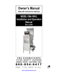
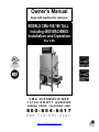
Owner’s Manual
Keep with machine for reference
MODELS CMA-180/180 TALL
Including 480V MACHINES
Installation and Operation
Rev 2.08
CMA DISHMACHINES
12700 KNOTT AVENUE
GARDEN GROVE, CALIFORNIA 92841
800-854-6417
FAX 714-895-2141
www.cmadishmachines.com
Table of Contents
Model CMA-180
1.
SPECIFICATIONS................................................................................................. 2
1.1
CMA-180/CMA-180T .................................................................................................................... 2
1.1.
CMA-180/CMA-180T .................................................................................................................... 3
2.
GETTING STARTED ............................................................................................ 4
2.1.
Introduction to CMA-180 ............................................................................................................... 4
2.2.
Receiving and Installation ................................................................................................................ 5
2.2.1. Electrical .................................................................................................................................... 5
2.2.2. Plumbing .................................................................................................................................... 5
2.2.3. Chemical Dispensers .................................................................................................................. 5
2.2.3.1.
Low Temperature Applications ...................................................................................... 6
2.2.4. Exhaust Fan Control Kit p/n 17528.00 Instructions................................................................. 7
2.2.5. Water Tempering Kit (Optional) ............................................................................................... 8
2.2.6. Installation Checklist ................................................................................................................... 9
2.2.7. Machine Start-Up Procedures for High Temp machines............................................................ 9
2.2.8. Electrical Requirements ..............................................................................................................11
3.
WIRING OPTIONS.............................................................................................. 12
4.
QUICK SERVICE GUIDE .................................................................................. 13
5.
INITIAL PARTS KIT P/N 1100.17 ..................................................................... 14
6.
AUTO-FILL SOLID STATE TIMER ................................................................ 15
7.
WIRE DIAGRAM FOR CMA-180 WITH BOOSTER HEATER................... 16
8.
WIRE DIAGRAM FOR CMA-180 BOOSTER ONLY .................................... 17
9.
WIRE DIAGRAM FOR CMA-180 WITHOUT BOOSTER HEATER .......... 18
10.
WIRE DIAGRAM FOR 480V 180 WITHOUT BOOSTER HEATER ........... 19
11.
WIRE DIAGRAM FOR 480V 180 WITH BOOSTER HEATER.................... 20
www.cmadishmachines.com
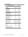
1. Specifications
1.1
Metric
Equivalent
CMA-180/CMA-180T
WATER CONSUMPTION
PER RACK
.82 G/1.24 G
(3.1 L/4.65 L)
PER HOUR
46.9 G/74.4 G
(177.5 L/281L)
WASH TIME-SEC
42/44
42/44
RINSE TIME-SEC
12/11
12/11
DWELL TIME-SEC
4/0
4/0
58 / 55
58 / 55
60
60
WASH TANK CAPACITY
8 GAL.
(30.3 L)
PUMP CAPACITY
68 GPM
(257 LPM)
WITHOUT BOOSTER HEATER
180°F
(82°C)
WITH BOOSTER HEATER
140°F
(60°C)
OPERATING CYCLE
TOTAL CYCLE-SEC
OPERATING CAPACITY
RACKS PER HOUR (NSF rated)
WATER REQUIREMENTS
WATER INLET
¾”
DRAIN CONNECTION
2”
5.1cm
20 PSI ±5 PSI
1.41 kg/cm
WASH-°F (High Temp)
155°F-160°F
RINSE-°F (High Temp)
180°F-195°F
WASH-°F (Low Temp)
140°F-150°F
(68°C/71°C)
(82°C/90°C)
(60°C/65°C)
RINSE-°F (Low Temp)
140°F-150°F
(60°C/65°C)
DEPTH
25”
(63.5cm)
WIDTH
25 ½”
RINSE PRESSURE SET
1.9cm
2
CYCLE TEMPERATURES
DIMENSIONS
HEIGHT
59”-60”
STANDARD TABLE HEIGHT
34”
MAX CLEARANCE FOR DISHES
17 ½”
DRAIN CONNECTION (OFF FLOOR)
MODEL CMA-180 INSTALLATION & OPERATION Rev. 2.08
11 ½“ – 12½“
(65cm)
(150-152cm)
(86.3cm)
(44cm)
(29-32cm)
Page 2
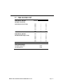
1.1. CMA-180/CMA-180T
VOLTS
PHASE
AMPS
208
1
36
240
1
38
208
3
24
240
3
26
480
3
10
ELECTRICAL RATING
208
1
78
WITH BOOSTER (High Temp)
240
1
88
208
3
49
240
3
55
480
3
25
ELECTRICAL RATING
WITHOUT BOOSTER
(both High and Low Temp)
SHIPPING WEIGHT
WITHOUT BOOSTER
WITH BOOSTER
MODEL CMA-180 INSTALLATION & OPERATION Rev. 2.08
332#
375#
Page 3
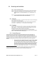
2. Getting Started
2.1.
Introduction to CMA-180
The C MA-180 is a hot water sanitizing, s ingle rack, door -type dishmachine. It i s a stand-alone
machine f eaturing a s elf-contained bo oster he ater ( optional). T he on ly external c onnections
necessary ar e po wer s upply, water s upply, dr ainpipe, and c hemical di spensers. T he m achine
utilizes recirculated wash water and fresh water final rinse. The CMA-180 can be converted both
as a straight through and corner with a door handle kit.
Operation of the CMA-180 is automatic. To initially fill the machine daily, press “Auto Fill” rocker
switch. Auto Fill timer will fill the machine until water begins to flow into the scrap trap. When the
door is opened and then closed, the wash cycle begins automatically. The wash tank heater will
maintain t he wash water temperature at 155°F. The booster he ater will produce a minimum of
180°F final rinse water each cycle providing the incoming water supply is a minimum 140°F.
This m achine can be us ed as a Lo w T emp machine pr ovided NSF S tandard 29 C hemical
Sanitizing Feeder (not supplied with machine) is installed.
This manual is structured to provide a complete reference guide to the CMA-180. It is presented
in a manner that all users will be able to comprehend and use as an effective tool in supporting
the operation and maintenance of the dishmachine. The first section explains how the machine is
packaged and what to look for when receiving the machine.
Instructions ar e provided i n the m anual ex plaining h ow t o unpack the m achine an d t hen i nstall
and s et u p t he m achine f or us e. R equirements ar e gi ven f or pl umbing, wiring, an d s pace
considerations. These attributes of the machine are always taken into consideration by our welltrained sales representatives prior to the order being placed. In the manual, additional installation
guidance is given to ensure the machine can run at optimum conditions.
The Operation Section of the manual may be used for instruction and procedures when required.
We make t his por tion of t he manual e asy to un derstand s o t hat a ll l evels of oper ators m ay be
able to read and comprehend the operation of the machine. The function of the machine itself is
mostly automatic a nd takes little t raining to put i nto f ull op eration. T he O peration Section also
includes diagnostic considerations for the machine when problems occur.
Our mission is to provide our customers with the highest quality products and the highest
quality service, always delivering more than we promise and more than he or she expects.
We will strive to do business the way the customer wants to do business, on a mutually
profitable basis.
We are committed to providing the best machines and customer service in the food
industry and your feedback is welcome.
DISCLAIMER OF LIABILITY OF WARRANTY: CMA EXPRESSLY DISCLAIMS ANY AND ALL WARRANTIES, EXPRESS OR IMPLIED, RELATING TO THE INSTALLATION OF ANY AND ALL
CMA EQUIPMENT THAT IS INSTALLED BY CHEMICAL DEALERS, CONTRACTED SERVICERS OR THIRD PARTY SERVICERS TO CMA EQUIPMENT. IF THE INSTALLATION
INSTRUCTIONS ARE NOT FOLLOWED EXACTLY (TO THE LETTER), OR, IF ANY PERSON OR COMPANY CONDUCTING THE INSTALLATION OF THE CMA EQUIPMENT, REVISE THE
INSTALLATION PROCEDURES OR ALTER THE INSTRUCTIONS IN ANY MANNER, THE CMA WARRANTY BECOMES VOID. IF, DUE TO THE IMPROPER INSTALLATION OF CMA
EQUIPMENT, THIS EQUIPMENT CEASES TO OPERATE PROPERLY OR AFFECTS OTHER PARTS OF THE CMA DISHWASHING EQUIPMENT, IN THAT THE OTHER PARTS BECOME
DEFECTIVE, THE CMA WARRANTY BECOMES VOID. CMA WILL NOT BE LIABLE OR RESPONSIBLE OR WARRANT CMA EQUIPMENT, DUE TO IMPROPER INSTALLATION OF ANY
CMA MODEL DISHWASHER.
MODEL CMA-180 INSTALLATION & OPERATION Rev. 2.08
Page 4
2.2.
Receiving and Installation
Step 1: Remove packaging material.
Step 2: Remove service manual and machine legs from inside the wash tank.
Step 3: Install legs into dishmachine leg lockets and adjust the feet. Set the
machine in place. Level the machine side – to – side and front – to –
back.
Step 4: It is recommended that a distance of at least eight inches (8”) be
between the table scrap sink and the dishmachine.
2.2.1. Electrical *
The control panel provides a 1” conduit connection point on the rear of the panel.
Refer to Section 3 for wiring options.
This machine is equipped to handle both single and three phase applications.
See Section 1: Specifications 1.1 for the proper electrical ratings.
2.2.2. Plumbing*
Minimum 140°F / Minimum 180°F (if machine ordered without booster heater,
water supply ¾” – minimum 20 psi, 6 gpm flow rate and 60 gph recovery rate.
Plumbing connection located on the top of the machine.
The drain is a two inch (2”) pipe sleeve attached by “No-Hub” plumbing
connection at the bottom of the scrap trap. Account’s drain should be no higher
than 11” to allow the machine to drain properly
2.2.3. Chemical Dispensers *
This machine must be operated with an automatic detergent feeder and, if applicable, an
automatic chemical sanitizer feeder, including a visual means to verify that detergents and
sanitizers are delivered or a visual or audible alarm to signal if detergents and sanitizers are not
available for delivery to the respective washing and sanitizing systems. Please see instructions
for electrical and plumbing connections located in this manual and in the feeder equipment
manual.
1.
Check valves should be installed directly at the mixing chamber coupling
located by the vacuum breaker on the back of machine. There are two
1/8” FPT mounting holes provided on the mixing chamber coupling,
which will position the check valves parallel to the machine avoiding any
chemicals from dripping onto the stainless steel should a leak develop.
One hole is for rinse chemical and one for sanitizer chemical, but only
one is needed with the High Temp machines — for rinse chemical only.
*
Electrical and plumbing connections must be made by qualified person who comply with all
available Federal, State, and Local Health, Electrical, Plumbing and Safety codes
MODEL CMA-180 INSTALLATION & OPERATION Rev. 2.08
Page 5
2.
Remove the plugs from the mixing chamber; and install injection fittings
(supplied with your dispenser).
3.
A 7/8” detergent injection hole is provided in the back of the wash tank.
Remove the S.S. plug and install the detergent fitting (supplied with your
dispenser).
4.
A 7/8” chemical probe hole is provided in the front of the wash tank
heater just below hi limit switch. Insert the probe into the hole from inside
the wash tank and secure it with the probe retaining nut provided.
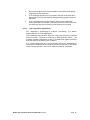
2.2.3.1.
Low Temperature Applications
See dispenser m anufacturing op erational
adjustments for Low Temp applications.
instructions f or s anitizer
The s anitizing p ump oper ates when t he f resh w ater ent ers t he m achine
during f inal r inse. T he w ater i s t reated at 50 PPM ( parts per million). T he
pressure regulator is adjusted to 20 PSI. This allows 0.82 gallons of water to
enter the machine each time a rack is washed.
It i s r ecommended t hat t he 5 -1/4% c hemical s olution be s tandardized t o
allow uniform dispensing of the sanitizing solution into the flow of rinse water
as the machine operates. At this level, maximum shelf life is available.
MODEL CMA-180 INSTALLATION & OPERATION Rev. 2.08
Page 6
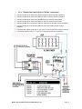
2.2.4. Exhaust Fan Control Kit p/n 17528.00 Instructions
1. Connect terminal #1 on timer block (Red) to heater contactor terminal marked L3
2. Connect terminal #3 on timer block (Blue) to heater contactor terminal marked L1
3. Connect terminal #2 on timer block (Red/Black) to fan contactor coil terminal.
4. Connect terminal #3 on timer block (Blue) to other fan contactor coil terminal
5. Connect terminal # 3 on timer block (Blue) to sixth cam top terminal on timer assembly.
6. Connect terminal #6 on timer block (Blue) to sixth cam middle terminal on timer
assembly.
7. Connect power source of 220 Vac or 110 Vac to L1 and L2 (N) on fan control contactor.
8. Connect exhaust fan motor to T1 and T2 on other side of fan control contactor.
MODEL CMA-180 INSTALLATION & OPERATION Rev. 2.08
Page 7
2.2.5.
Water Tempering Kit (Optional)
MODEL CMA-180 INSTALLATION & OPERATION Rev. 2.08
Page 8
2.2.6. Installation Checklist
Dishmachine checked for concealed damage.
Hot water supply is 140° (60°C)
Incoming water supply line is ¾”.
Incoming water supply is 6 gpm minimum capable at 20 psi flow pressure.
Machine circuit breaker is properly sized.
Service voltage and phase type are correct to machine data plate.
High leg of voltage is connected to L2 (three-phase).
Dishmachine is properly ventilated.
Floor drain plumbing is installed with air gap. MUST MEET LOCAL CODES.
Dishmachine is properly grounded.
Dishmachine is properly leveled.
Dishrack guides are adjusted to level of dishtable.
Machine circuit breaker is labeled D/W
2.2.7. Machine Start-Up Procedures for High Temp machines.
1. Place the scrap baskets over the wash tanks.
2. Secure the wash & rinse arms and check the free-spin.
3. Open the control panel and select ‘normal” toggle switch position.
4. Adjust the rinse pressure to 20 PSI flow pressure using the regulator and the gauge
provided on machine.
a. Turn the power switch to the “Off” position.
b. Close doors and press “Auto Fill” rocker switch;the water overflows into the scrap
trap.
c.
Turn the power switch to “on” position. SEE NOTE FOR BOOSTER HEATER
BELOW.
d. While holding “flush” toggle switch, to activate the water solenoid, adjust the
pressure regulator until the gauge reads 20 PSI. NOTE: Booster heater is filled
during this procedure.
5. Connect the detergent and rinse dispenser to the power block supplied & labeled inside
the control panel (208-220) volt.
6. Remove the plug from the mixing chamber and install the rinse injection fitting.
7. A 7/8” chemical probe hole is provided in the wash tank behind wash tank heater cover.
8. A 7/8” detergent fitting hole is provided in the wash tank behind the machine.
9. Check the machine operating temperatures. Adjust if necessary.
a. After the machine has warmed up for five to ten minutes (5 – 10 min.), observe
the wash and rinse temperatures. The wash temperature must be 155°F
MODEL CMA-180 INSTALLATION & OPERATION Rev. 2.08
Page 9
minimum. The rinse temperature must be 180°F minimum. If necessary, adjust
the temperatures by removing the panel in front of the respective heater and
turning the adjustment stem clockwise to increase.
NOTE: Rinse water temperature must be observed during the rinse cycle.
10. Check all water and drain fittings for leaks.
11. Install the wall chart and instruct the machine operator on the proper cleaning and
operation of the CMA-180.
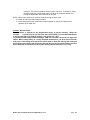
Caution: Booster Heater
Booster heater is shipped on the dishmachine empty to prevent freezing. When the
machine
is powered up for the first time, the booster heater must be filled immediately
to prevent damage to the heating element. See Section 2.2.7 (4d.)
To prevent booster heater element damage, CMA has removed a wire from the high limit
switch. When initially filling of a newly installed dishmachine, you must fill the booster
tank prior to connecting the removed wire. When water is observed entering the wash tank
this indicates the booster tank is full and removed wire can be connected. Failure to follow
these important instructions will destroy the heating element because of dry -firing.
MODEL CMA-180 INSTALLATION & OPERATION Rev. 2.08
Page 10
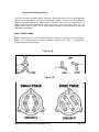
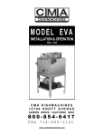
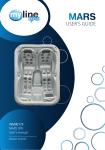
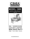
2.2.8. Electrical Requirements
The C MA-180 c omes standard f actory, w ired f or 3 -phase oper ation. C heck t he el ectrical d ata
plate to c onfirm t his. Refer to “ Electrical Requirements” Figure 1-A, for pr oper wiring instruction
for bot h r ectangular booster and wash he aters c onversion. Also c heck t he wiring di agram t o
properly wire t he t erminal po wer b lock, t ank heat er, and booster h eater f or 1 phas e ( or 1B
diagram below). Refer to Figure 1-B, for proper wiring instruction for both triangular booster and
wash heaters conversion.
SINGLE PHASE POWER
NOTE: 80amp s ervice i s r equired when CMA-180 is wired f or s ingle-phase w ith the boos ter
heater. S ee “ Wiring opt ions” s ection f or DUAL 1-phase po wer supply. C ircuit br eaker
requirement (1) 50 amp & 30 amp
Figure 1-A
Figure 1-B
MODEL CMA-180 INSTALLATION & OPERATION Rev. 2.08
Page 11
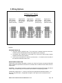
3. Wiring Options
3-Phase and 1 Phase
Wiring Options
Single-Source
220V 3-Phase
(20 amp/12 g*)
(Without booster)
Single-Source
220V 3-Phase
(50 amp/8 g*)
Standard
Single-Source
220V 1-Phase
(80 amp/4 g*)
Two-Source
220V 1-Phase
(50 amp/8 g*)
(30 amp/10 g*)
Single-Source
220V 1-Phase
(30 amp/10 G*)
(Without booster)
*g=gauge
DISPENSER HOOK-UP
1. The pow er s ignal i s 208 /230 v olts. T he po wer bl ock i s l abeled i nside t he c ontrol box .
Conduit holes for both detergent & rinse are supplied on the control box.
2. A t hreaded ( 1/8”) i njection po int is pr ovided o n t he final r inse T eflon m ixing c hamber
located off the back of the machine.
3. A (7/8”) hole is provided in the tank for a probe access. It is located on the front side of
the wash tank inside the heater cover.
MAIN POWER CONNECTION
Please refer to the machine data plate or choose one of the five (5) power connections illustrated
above. E lectrical requirements are s hown for m achines with or w ithout boos ter heat er, three or
single phase.
WARNING: Insure that the machine is properly grounded and complies with all local and national
codes. Injury or death may occur from shock, if the machine is not properly grounded.
Install power supply wires, L1, L2 and L3 (3-Phase) to the appropriate terminals marked L1, L2,
and L3 on the power block. (If applicable, the high or “wild” leg must be connected to the L2
Terminal.)
MODEL CMA-180 INSTALLATION & OPERATION Rev. 2.08
Page 12
4. Quick service guide
MODEL: CMA 180 HIGH TEMP
TECHNICAL ISSUE
Door magnetic reed switch problem
Door mechanical switch problem
Pump motor not running
Pump motor runs continuous
CAUSE
Faulty magnetic reed switch
SOLUTION
Check wire connections inside control box
Switch alignment issue
Contact factory for new retrofit, corner P/N 00566.10
straight P/N 00566.20
Align switch
Switch button broke
Replace switch, P/N00562.00
Delimer switch is in OFF position
Flip to NORMAL position
Loose wire connections
Check and crimp connectors
Faulty # 3 micro switch in cam timer
Replace micro switch, P/N 00411.00
Faulty contactor
Replace contactor, P/N 00404.85
Faulty wash pump motor
Replace wash pump motor, P/N 00201.00
Faulty # 3 micro switch in cam timer
Replace micro switch, P/N 00411.00
Delimer switch is in DELIME position
Flip to NORMAL position
Faulty contactor
Replace contactor, P/N 00404.85
Booster heater thermostat not properly set
Adjust thermostat
Incoming main water temperature below 140 F Raise water temperature to 140 F
Final rinse water below 180 degree F
Wash tank heater is not operational
Tripped or faulty high limit switch
Reset or replace high limit switch, P/N 17523.51
Faulty contactor
Replace contactor, P/N 13003.17
Faulty booster heater element
Replace heating element, P/N 13417.67
Scaled heating element
Thermostat is not properly adjusted
De- scale heating element
Adjust thermostat
Loose lead connection
Tripped or faulty high limit switch
Check connectors and secure
Reset or replace high limit switch, P/N 17523.51
Faulty float switch
Replace float switch, P/N 13463.00
Faulty contactor
Replace contactor, P/N13003.50
Faulty heating element
Replace heating element, P/N 13417.65
Water regulator not adjusted properly
Adjust regulator to 18-20 PSI
Clogged final rinse spray jets
Low water pressure at the final rinse Missing final rinse spray end cap
Water solenoid leaks
Low incoming water pressure from building
Scaled or dirty solenoid valve
Increase pressure
Faulty solenoid valve diaphragm
Thermostat not properly set
Replace diaphragm, P/N 00706.00
Adjust thermostat
Wash water temperature too low/high Scaled heating element
Machine does not operate when the
door is closed
Clean jets
Replace end cap, P/N 00308.17
Clean valve
Clean scale, delime machine
Faulty temperature gauge
Position or proper operation of door switch
Replace gauge, P/N 03202.00
Adjust or replace door switch, P/N 00557.55
Delimer switch is on OFF position
Faulty 1st micro switch in cam timer
Flip to NORMAL position
Replace micro switch, P/N 00411.00
Check cam timer motor
Replace timer if needed, P/N 00409.17
Check ice cube relay
Replace if faulty, P/N 00631.05
Replace contactor, P/N 00404.85
Faulty wash pump contactor
MODEL CMA-180 INSTALLATION & OPERATION Rev. 2.08
Page 13
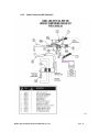
5. INITIAL PARTS KIT P/N 1100.17
P/N
00121.18
00200.10
00206.00
00302.19
00304.17
00304.19
00308.17
00308.50
00363.00
00404.85
00405.00
00411.00
00421.78
00421.90
00475.00
00501.17
00562.00
00602.00
00631.05
00706.00
00735.00
00738.15
03202.00
03202.00
03408.55
13003.17
13003.50
13304.55
13415.00
13417.47
13422.71
13417.85
13463.10
13605.00
15518.00
17523.51
DESCRIPTION
CMA-180 Drain Stopper O Ring
Pump Assy 110/220V 60 Hz (Open)
Pump Seal Kit
CMA-180 Buna Gasket (#302.17)
CMA-180 Wash Spray Arm
CMA-180 Rinse Arm W/Bearing
CMA-180 Rinse Arm SS End Plug
Spray Arm End Plug SS
Spray Base Lock Pin
Contactor 208.240V 20AMP
Start/Fill Switch Toggle
Micro Switch
CMA-180 Illuminated Plug
CMA-180 Power Switch
Toggle Switch DPDT 15 AMP/Delimer
Timer Motor Assy 60 Sec. 220V/60Hz
Roller Door Switch
Door Spring
Ice Cube Relay 220V
¾ Water Solenoid Repair Kit JE
¾ Vac Breaker Rep Kit Watts
¾ Solenoid Coil JE 220V
Thermometer CMA-180 “Wash”
Thermometer CMA-180 “Rinse”
Counter (Face Mount Sm) 220/50
Contactor 60 AMP 3 Pole
Contactor 30 AMP
SS Final Rinse Spray Jet – HT
EGO Thermostat Retrofit Kit Rinse
CMA-180 Booster Heater Gasket
Immersion Heater 12 Kw 3PH/1PH, 240V
Thermostat Heater CMA-44/CMA-180 Wash
Liquid Level Switch SS – CMA-44
Pressure Gauge
Immersion Heater 6 Kw 3hp/1ph, 240V
Hi Limit Switch 250 deg
NO. REQ’D
1
1
1
1
1
1
1
1
1
1
1
1
1
1
1
1
1
1
1
1
1
1
1
1
1
1
1
1
1
1
1
1
1
1
1
1
NOTE: CMA recommend that this Model CMA-180 initial parts kit be
kept on hand, as a back up supply, in the event your machine should
require emergency service. All the parts included in this kit are
unique to the CMA-180 dishmachine, and are essential to the “quality”
operation and customer service to the CMA-180 unit.
MODEL CMA-180 INSTALLATION & OPERATION Rev. 2.08
Page 14
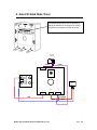
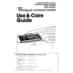
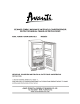
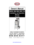
6. Auto-Fill Solid State Timer
Pre-selected delay period can be adjusted by
turning dip switches on for proper time setting.
Removal of input power will reset the control.
AUTO-FILL
SWITCH
violet
violet
L2
L1
WASH PUMP
CONTACTOR
6
T2
WATER
SOLENOID
VALVE
T1
1
2
3
red
blue
MODEL CMA-180 INSTALLATION & OPERATION Rev. 2.08
orange
blue
Page 15
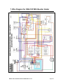
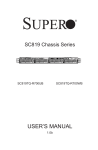
7. Wire Diagram for CMA-180 With Booster Heater
MODEL CMA-180 INSTALLATION & OPERATION Rev. 2.08
Page 16
{
L1
GND
L3
L2
L1
L3
L2
L1
L3
L2
L1
HEATER
CONTACTOR
DETERGENT
BOOSTER
HEATER
CONTACTOR
L2
GROUND
RINSE SIGNAL {
WASH PUMP
CONTACTOR
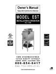
8. Wire Diagram for CMA-180 Booster Only
T2
T1
T3
T2
T1
T3
T2
T1
PUMP
MOTOR
MODEL CMA-180 INSTALLATION & OPERATION Rev. 2.08
HI LIMIT
SWITCH
5kW
ADJ.
THERMOSTAT
WASH TANK
HEATER
12kW
BOOSTER
HEATER
Page 17
9. Wire Diagram for CMA-180 Without Booster Heater
MODEL CMA-180 INSTALLATION & OPERATION Rev. 2.08
Page 18
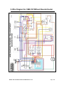
10. Wire Diagram for 480V 180 Without Booster Heater
MODEL CMA-180 INSTALLATION & OPERATION Rev. 2.08
Page 19
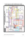
11. Wire Diagram for 480V 180 With Booster Heater
MODEL CMA-180 INSTALLATION & OPERATION Rev. 2.08
Page 20