1
OB252C-1.qxp
02.4.25 11:27 AM
Page 1
NOTE: • This service Manual covers only change points.
Please refer to the Service Manual OB227 REVISED
EDITION-B for unchanged contents.
• Please refer to the following service manual when the
outdoor unit is the under mentioned model.
MXZ-32SV- E1 : OB254
MXZ-18TV- E1 : OB280
MUX-19/20/25TV- E1 : OB284
• Please void OB252 REVISED EDITION-B.
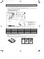
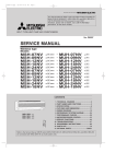
SPLIT-TYPE, AIR CONDITIONERS
SPLIT-TYPE, HEAT PUMP AIR CONDITION
No. OB252
REVISED EDITION-C
SERVICE MANUAL
Wireless type
Models
MSC-07RV
MSC-09RV
MSC-12RV
MSC-07RV
MSC-09RV
MSC-12RV
MSC-07RV
MSC-09RV
MSC-12RV
MSC-07RV
MSC-09RV
MSC-12RV
MSC-07RV
MSC-09RV
MSC-12RV
MSC-07RV
MSC-09RV
MSC-12RV
-
E2 (WH)
E2 (WH)
E2 (WH)
E3 (WH)
E3 (WH)
E3 (WH)
E4 (WH)
E4 (WH)
E4 (WH)
E2 (WH)
E2 (WH)
E2 (WH)
E3 (WH)
E3 (WH)
E3 (WH)
E4 (WH)
E4 (WH)
E4 (WH)
·
·
·
·
·
·
·
·
·
·
·
·
·
·
·
·
·
·
MU-07RV MU-09RV MU-12RV MU-07RV MU-09RV MU-12RV MU-07RV MU-09RV MU-12RV MUH-07RV
MUH-09RV
MUH-12RV
MUH-07RV
MUH-09RV
MUH-12RV
MUH-07RV
MUH-09RV
MUH-12RV
E2
E2
E2
E3
E3
E3
E4
E4
E4
-
E2
· MUX-10RV · MUX-18RV · MUX-24RV -
E2
E2
E2
E3
E3
E3
E4
E4
E4
Multi system type
MSC-07RV MSC-09RV MSC-12RV -
E2 (WH)
E2 (WH)
E2 (WH)
E2
E2
Inverter controlled multi system type
· MXZ-18RV -
E2
CONTENTS
MSC-07RV MSC-09RV MSC-12RV -
E4
E4
E4
1.
2.
3.
4.
5.
6.
7.
8.
TECHNICAL CHANGES ····································3
PART NAMES AND FUNCTIONS······················8
SPECIFICATION···············································11
WIRING DIAGRAM ··········································13
REFRIGERANT SYSTEM DIAGRAM ··············15
MICROPROCESSOR CONTROL ····················16
TROUBLESHOOTING······································16
PARTS LIST ·····················································27
OB252C-1.qxp
02.4.25 11:27 AM
Page 2
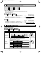
REVISION
Parts numbers have been partially modified.
Model
MSC-07/09/12RV- E1
MSC-07/09/12RV- E2
MSC-07/09/12RV- E2
Page
Part name
Part number
P27
REMOTE CONTROLLER HOLDER
E02 504 426 ➔ E02 141 083
P27
REMOTE CONTROLLER
E02 141 083 ➔ E02 504 426
OB252C-1.qxp
02.4.25 11:27 AM
1
Page 3
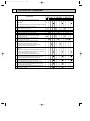
TECHNICAL CHANGES
Circle shows the change point of the model.
No.
Change point
1
2
3
4
5
6
7
8
9
10
11
12
13
MSC-09RV-
MSC-07RVE1
The specifications of Indoor and Outdoor fan motor.
The data of Med. and Low speed are added to Indoor fan motor
specification✼
✼The data value of indoor fan motor does not change if the indoor
unit is connected to a multi-type outdoor unit.
Remote controllers of COOL ONLY or COOL & HEAT
type are outdoor unit accessory.
Remote controller is included as an indoor unit accessory.
Two-way common remote controller
Two-way (using dip switch) remote controller
The specification of electronic control P.C. board is
compatible with remote controllers of COOL ONLY
and COOL & HEAT type.
Indoor electronic control P.C. board has changed
for two-way remote controller.
Indoor electronic control P.C. board has changed
for two-way remote controller.
Microprocessor programing flow has changed.
Electronic control P.C. board for E3 is interchangeable
with the one for E2 (except for MSC-12RV).
(New P.C. board) Indoor electronic control P.C. board has
changed.
Earth wire from the board is fixed to the electrical box with screw.
The shape of connector CN211 has changed. Indoor electronic
control P.C. board has been connected with
Power monitor, receiver P.C. board using connector.
When fan speed is set to"Auto", initial temperature difference
specitying changing fan speed has been improved in order to
reach the set temperature faster than E1, E2, and E3.
The mark of terminal block has changed. Terminal block for E4 is
interchangeable with the ones for E1, E2 and E3.
Winding resistance and shape of fan motor have changed.
Fan motor for E4 is not interchangeable with the ones for E1,
E2 and E3 except for MSC-12RV.
Fan motor rubber mount has changed because the shape of
fan motor was changed.
3
E2
E3
E4
E1
E2
E3
E4
MSC-12RVE1
E2
E3
E4
OB252C-1.qxp
02.4.25 11:27 AM
Page 4
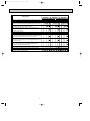
Circle shows that change points apply to the models.
No.
Change point
1 Remote controller of COOL ONLY type is outdoor unit accessory.
2 Remote controller is included as an indoor unit accessory.
3
4
5
6
7
8
9
10
11
12
13
MU-09RV-
MU-07RVE1
Compressor contactor (52C) has changed. Compressor
contactor for E2,E3,E4 are interchangeable with the ones for E1.
Compressor has changed. Compressors for E3 and E4 are not
interchangeable with the ones for E1 and E2.
Compressor capacitor has changed. Due to different shape,
compressor capacitor for E4 is not interchangeable with the
ones for E1, E2 and E3.
Fuse has been removed.
Wiring diagram has changed because fuse was removed.
The shape of propeller fan has changed. The number of
propeller fan has changed from four to three. Propeller fan for E4
is not interchangeable with the ones for E1, E2 and E3.
The shape, diameter of axis and fan speed of fan motor have
changed. Fan motor for E4 is not interchangeable with the ones
for E1, E2 and E3.
Fan motor capacitor has changed. 1.5+➔ 2.0+
Fan motor capacitor for E4 is not interchangeable with the
ones for E1, E2 and E3(MU-12RV only).
Refrigerant filing capacity has changed. 0.85kg➔ 0.80kg
The method of troubleshooting for outdoor unit has changed.
The repairing procedure when outdoor unit does not stop
has been added to troubleshooting.
4
E2
E3
E4
E1
E2
E3
MU-12RVE4
E1
E2
E3
E4
OB252C-1.qxp
02.4.25 11:27 AM
Page 5
Circle shows that change points apply to the models.
Change point
No.
1
2
3
4
5
6
7
8
9
10
11
12
13
14
15
16
17
Remote controller of COOL & HEAT type is outdoor unit
accessory.
Remote controller is included as an indoor unit accessory.
Accumulator has been removed.
Compressor has changed.
Compressor capacitor has changed. Due to different
shape, compressor capacitor for E4 is not interchangeable
with the ones for E1,E2 and E3.
The mark of terminal block has changed. Terminal block
for E4 is interchangeable with the ones for E1, E2 and E3.
Deicer P.C. board has changed. Jumper wire of compulsory
defrosting mode has changed. (JP607-R853➔JPDS-JPSG)
Jumper wire for defrost setting has changed.
(JPC-JPE➔JRF-JRG) (Refer to page 26.)
The defrosting intervals which are changed by setting a short
circuit are the same as E1, E2, and E3.
Deicer P.C. board for E4 is not interchangeable with the
ones for E1, E2 and E3.
Wiring diagram has changed according to the following
reasons; the shape of connectors CN711 and CN661 has
changed and R.V. coil relay (X62) has changed into SSR (SR62).
X62 has changed into SR62 in Example of Operation
time chart in HEAT operation.
Compared to E1, E2, and E3, no change has been made about
the operational condition for defrosting and tne control system of
R.V. coil (timing of switching on/off).
The shape of propeller fan has changed. The number of
propeller fan has changed from four to three. Propeller
fan for E4 is not interchangeable with the ones for E1,E2, and E3.
The shape and diameter of axis of fan motor have changed.
The shape of connector has changed.
Fan motor and connector for E4 are not interchangeable
with those for E1, E2 and E3.
Refrigerant filling capacity has changed. 0.80kg➔ 0.85kg
The method of checking serial signal error for E4 has been added.
The method of troubleshooting for outdoor unit has changed.
The method for checking thermistor has been added to
troubleshooting.
The method for checking 4-way valve has been added to
troubleshooting.
The repairing procedure when outdoor unit does not stop has
been added to troubleshooting.
MUX-10RV - E1
MUX-18RV - E1
MUX-24RV - E1
MXZ-18RV - E1
MUH-09RV-
MUH-07RVE1
MUX-10RV - E2
MUX-18RV - E2
MUX-24RV - E2
MXZ-18RV - E2
1. Remote controller is unprovided as the outdoor unit accessory.
5
E2
E3
E4
E1
E2
E3
E4
MUH-12RVE1
E2
E3
E4
OB252C-1.qxp
02.4.25 11:27 AM
Page 6
Reference
REMOTE CONTROLLER
Model
COOL ONLY
COOL
& HEAT
TWO-WAY
TWO-WAY
DIP switch
✕
✕
✕
MS-07/09/12RV- E1
MSH-07/09/12RV-
E1
✕
w When HEAT mode is selected
w
MS-07/09/12RV- E2
MSH-07/09/12RVMS-07/09/12RV- E3
✕
MSH-07/09/12RV- E3
✕
E2
by the remote controller of
COOL & HEAT type, the unit
will operate in FAN mode.
MS-07/09/12RV- E4
MSH-07/09/12RV- E4
MSC-07RV - E1
MSC-09RV - E1
MSC-12RV - E1
MU-07RV - E1
MU-09RV - E1
MU-12RV - E1
MUH-07RV - E1
MUH-09RV - E1
MUH-12RV - E1
✕
MSC-07RV - E2
MSC-09RV - E2
MSC-12RV - E2
MU-07RV - E2
MU-09RV - E2
MU-12RV - E2
MUH-07RV - E2
MUH-09RV - E2
MUH-12RV - E2
COOL ONLY REMOTE CONTROLLER
COOL&HEAT REMOTE CONTROLLER
TWO-WAY REMOTE CONTROLLER
TWO-WAY REMOTE CONTROLLER
1. Both of COOL ONLY and COOL & HEAT remote controller are unified into a two-way remote controller.
2. FAN mode operation is available in COOL ONLY unit. In this case the set room temperature
will be displayed on the remote controller, however, the room temperature can not be controlled by remote controller button.
HEAT operation is available in only HEAT & COOL type unit.
MSC-07RV - E2
MSC-09RV - E2
MSC-12RV - E2
MSC-07RV - E3
MSC-09RV - E3
MSC-12RV - E3
TWO-WAY REMOTE CONTROLLER
TWO-WAY DIP SWITCH REMOTE CONTROLLER
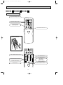
• Outlines and dimensions have been changed.
19
162
58
Wireless remote controller
6
OB252C-1.qxp
02.4.25 11:27 AM
Page 7
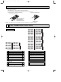
• The way of remodelling individual operation of P.C Board of remote controller has changed.
A maximum of 4 indoor units with wireless remote controllers can be used in a room.
In this case, to operate each indoor unit individually by each remote controller, P.C. boards of remote controller must be
modified according to the number of the indoor unit.
How to modify the remote controller P.C. board
Remove batteries before modification.
The board has a print as shown below :
NOTE : For remodelling, take out the batteries and press the
OPERATE/STOP(ON/OFF)button
twice or 3 times at first.
After finish remodelling, put back
the batteries then press the
RESET button.
The P.C. board has the print “J1” and “J2”. Solder “J1” and “J2” according to the number of indoor unit as shown
in Table 1. After modification, press the RESET button.
Table 1
1 unit operation
2 units operation
3 units operation
4 units operation
No. 1 unit
No modification
Same as at left
Same as at left
Same as at left
No. 2 unit
–
Solder J1
Same as at left
Same as at left
No. 3 unit
–
–
Solder J2
Same as at left
No. 4 unit
–
–
–
Solder both J1 and J2
REMOTE CONTROLLER (How to set the type)
This remote controller setting needs to be switched according to the type of air conditioner (COOL & HEAT or COOL
ONLY).
If the setting is incorrect, the air conditioner does not operate normally. Therefore, check if the setting corresponds to
the type of air conditioner. If it does not, correct the setting as shown below.
Slide switch
Type
The position
of the slide
switch
7
COOL & HEAT COOL ONLY
OB252C-1.qxp
02.4.25 11:27 AM
Page 8
• How to replace batteries
Weak batteries may cause the remote controller malfunction.
In this case, replace the batteries to operate the remote controller normally.
1 Remove the front lid and insert batteries.
Then re-attach the front lid.
/
2 Press the RESET button.
HE
/FA AT
N
/
HE
/FA AT
N
Insert the negative pole
of the batteries first.
Check if the polarity of
the batteries are correct.
RESET button
NOTE : If the RESET button is not pressed, the remote controller may not operate correctly.
2
PART NAMES AND FUNCTIONS
MSC-07RV
MSC-09RV
MSC-12RV
MSC-07RV
MSC-09RV
MSC-12RV
MSC-07RV
MSC-09RV
MSC-12RV
MSC-07RV
MSC-09RV
MSC-12RV
MSC-07RV
MSC-09RV
MSC-12RV
MSC-07RV
MSC-09RV
MSC-12RV
ACCESSORIES
MSC-07RV
MSC-09RV
MSC-12RV
MSC-07RV
MSC-09RV
MSC-12RV
- E1
- E1
- E1
- E1
- E1
- E1
•
•
•
•
•
•
MU-07RV - E1
MU-09RV - E1
MU-12RV - E1
MUH-07RV - E1
MUH-09RV - E1
MUH-12RV - E1
- E2
- E2
- E2
- E2
- E2
- E2
- E3
- E3
- E3
- E3
- E3
- E3
- E4
- E4
- E4
- E4
- E4
- E4
•
•
•
•
•
•
•
•
•
•
•
•
•
•
•
•
•
•
MU-07RV - E2
MU-09RV - E2
MU-12RV - E2
MUH-07RV - E2
MUH-09RV - E2
MUH-12RV - E2
MU-07RV - E3
MU-09RV - E3
MU-12RV - E3
MUH-07RV - E3
MUH-09RV - E3
MUH-12RV - E3
MU-07RV - E4
MU-09RV - E4
MU-12RV - E4
MUH-07RV - E4
MUH-09RV - E4
MUH-12RV - E4
<Indoor unit>
<Indoor unit>
1 Installation plate
1
2 Installation plate fixing screw 4 o 25 mm
5
3 Remote controller mounting hardware
1
4 Fixing screw for 3 3.5 o 16 mm
2
5 Battery (AAA) for remote controller
2
6 Felt tape (Used for left or left-rear piping)
1
7 Deodorizing filter
1
8 Air cleaning filter
1
<Outdoor unit>
1 Installation plate
2 Installation plate fixing screw 4 o 25 mm
1
3 Remote controller mounting hardware
4 Fixing screw for 3 3.5 o 16 mm
1
5 Battery (AAA) for remote controller
6 Wireless remote controller
2
7 Felt tape (Used for left or left-rear piping)
8 Deodorizing filter
1
9 Air cleaning filter
1
5
2
1
1
<Outdoor unit: MUH type>
9 Wireless remote controller
1
0 Drain socket
1
0 Drain socket: MUH type
1
1 Drain cap
2
1 Drain cap: MUH type
2
8
OB252C-1.qxp
02.4.25 11:27 AM
Page 9
MSC-07RV - E2 MSC-09RV - E2 MSC-12RV - E2
REMOTE CONTROLLER
Signal transmitting section
Operation display section
AM
CLOCK
PM
6 00 1 1 00
OPERATE /STOP
(ON /OFF)button
ON/OFF
TOO
WARM
TOO
COOL
OPERATION SELECT button
TEMPERATURE buttons
MODE
I FEEL COOL DRY HEAT/FAN
VANE
FAN
VANE CONTROL button
FAN SPEED CONTROL button
ECONO COOL
ECONO COOL button
STOP
START
ON-TIMER button
CLOCK SET button
HR. button
MIN. button
(TIME SET button)
OFF-TIMER button
HR. CLOCK MIN.
RESET
9
RESET button
OB252C-1.qxp
02.4.25 11:27 AM
Page 10
MSC-07RV - E3 MSC-09RV - E3 MSC-12RV - E3
MSC-07RV - E4 MSC-09RV - E4 MSC-12RV - E4
REMOTE CONTROLLER
Signal transmitting section
Operation display section
PM
AM
OPERATE /STOP
(ON /OFF)button
TOO
ON/OFF WARM
TOO
COOL
TEMPERATURE buttons
Open the front lid.
CLOCK
PM
AM
TOO
ON/OFF WARM
FAN SPEED CONTROL button
TOO
COOL
FAN
STOP
VANE
START
I FEEL COOL
HEAT
/FAN
OFF-TIMER button
DRY
ON-TIMER button
/
MODE
HR.
ECONO COOL
MIN.
OPERATION SELECT button
ECONO COOL button
HR. button
MIN. button
(TIME SET button)
RESET CLOCK
CLOCK SET button
RESET button
VANE CONTROL button
10
OB252C-1.qxp
02.4.25 11:27 AM
3
Page 11
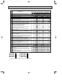
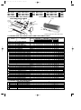
SPECIFICATION
Indoor model
Function
Indoor unit power supply
Special
remarks
Fan
motor
Electrical
data
Capacity Air flow(High/Med.w/Low w )
Power outlet
Running current
Power input
Power factor
Starting current
Fan motor current
Model
Winding
resistance(at20:)
Dimensions WOHOD
Weight
Air direction
Sound level(High/Med.w/Loww )
Fan speed (High/Med.w/Low w)
Fan speed regulator
Thermistor RT11(at25:)
Thermistor RT12(at25:)
Outdoor model
K /h
A
A
W
%
A
A
"
mm
kg
dB
rpm
k"
k"
kW
Capacity
R/h
Dehumidification
K /h
Outdoor air flow
A
Power outlet
A
Running current
W
Power input
A(kW)
Auxiliary heater
%
Power factor
A
Starting current
A
Compressor motor current
A
Fan motor current
Coefficient of performance(C.O.P)
Model
W
Output
Winding
"
resistance(at20:)
Model
Winding
"
resistance(at20:)
mm
Dimensions WOHOD
kg
Weight
dB
Sound level
rpm
Fan speed
Fan speed regulator
Refrigerant filling
kg
capacity(R22)
cc
Refrigerating oil (Model)
Special
remarks
Fan
motor Compressor
Electrical
data
Capacity
Outdoor unit power supply
MSC-07RV - E4
Cooling
Single phase
220-240V,50Hz
474/384w/294w
10
0.17
35
93.6-85.8
—
0.17
RC4V19-LA
WHT-BLK 413
BLK-RED 334
850O278O191
9
5
36/31w/26 w
950/790w/640 w
3
10
10
MU-07RV - E4
Single phase
220-240V,50Hz
2.2
0.8
1620-1752
10
2.98-2.93
645-675
—
98.4-96.0
19
2.77-2.71
0.21-0.22
3.24-3.10
RH-130VGCT
650
C-R 4.18
C-S 5.76
RA6V23-FC
WHT-BLK 353
BLK-RED 321
780o540o255
32
44-45
710-760
1
MSC-09RV - E4
Cooling
Single phase
220-240V,50Hz
474/384w/294w
10
0.17
35
93.6-85.8
—
0.17
RC4V19-LA
WHT-BLK 413
BLK-RED 334
850O278O191
9
5
36/31w /26 w
950/790w/640 w
3
10
10
MU-09RV - E4
Single phase
220-240V,50Hz
2.5
1.1
1620-1752
10
3.43-3.28
745-775
—
98.7-98.5
20
3.22-3.06
0.21-0.22
3.21-3.09
RH-140VGCT
700
C-R 4.03
C-S 5.71
RA6V23-FC
WHT-BLK 353
BLK-RED 321
780o540o255
32
44-45
710-760
1
MSC-12RV - E4
Cooling
Single phase
220-240V,50Hz
588/468w/360w
10
0.19
40
95.7-87.7
—
0.19
RC4V19-GA
WHT-BLK 375
BLK-RED 294
850O278O191
10
5
39/34w/29 w
1020/850w/690 w
3
10
10
MU-12RV - E4
Single phase
220-240V,50Hz
3.5
1.6
1848-1980
10
6.01-6.16
1270-1350
—
96.1-91.3
35
5.72-5.84
0.29-0.33
2.67-2.52
RH-220VHAT
1050
C-R 2.13
C-S 3.91
RA6V33-DC
WHT-BLK 301
BLK-RED 332
780o540o255
34
49
810-840
1
0.80
0.80
0.88
300 (MS56 )
NOTE: Test conditions are based on ISO 5151.
Cooling : Indoor DB27°C WB19°C
Outdoor DB35°C WB24°C
Indoor-Outdoor piping length 5m
w Reference value
11
300 (MS56 )
520 (MS56)
OB252C-1.qxp
02.4.25 11:27 AM
Page 12
Indoor model
Function
Indoor unit power supply
Special
remarks
Fan
motor
Electrical
data
Capacity Air flow(High/Med.w/Low w)
Power outlet
Running current
Power input
Power factor
Starting current
Fan motor current
Model
Winding
resistance(at20:)
Dimensions WOHOD
Weight
Air direction
Sound level(High/Med.w/Loww )
Fan speed(High/Med.w/Loww )
Fan speed regulator
Thermistor RT11(at25:)
Thermistor RT12(at25:)
Outdoor model
K /h
A
A
W
%
A
A
"
mm
kg
dB
rpm
k"
k"
Outdoor unit power supply
Special
remarks
Fan
Compressor
motor
Electrical
data
Capacity
kW
Capacity
R/h
Dehumidification
K /h
Outdoor air flow
A
Power outlet
A
Running current
W
Power input
A(kW)
Auxiliary heater
%
Power factor
A
Starting current
A
Compressor motor current
A
Fan motor current
Coefficient of performance(C.O.P)
Model
W
Output
Winding
"
resistance(at20:)
Model
Winding
"
resistance(at20:)
mm
Dimensions WOHOD
kg
Weight
dB
Sound level
rpm
Fan speed
Fan speed regulator
Refrigerant filling
kg
capacity(R22)
cc
Refrigerating oil (Model)
k"
Thermistor RT61(at0:)
MSC-09RV - E4
MSC-12RV - E4
MSC-07RV - E4
Heating
Heating
Heating
Cooling
Cooling
Cooling
Single phase
Single phase
Single phase
220-240V,50Hz
220-240V,50Hz
220-240V,50Hz
474/384 w/294 w 504/414 w/336w 474/384 w/294w 504/414 w/336w 588/468 w/360w 642/516w /402w
10
10
10
0.17
0.17
0.19
35
35
40
93.6-85.8
93.6-85.8
95.7-87.7
—
—
—
0.17
0.17
0.19
RC4V19-LA
RC4V19-LA
RC4V19-GA
WHT-BLK 413
WHT-BLK 413
WHT-BLK 375
BLK-RED 334
BLK-RED 334
BLK-RED 294
850O278O191
850O278O191
850O278O191
9
9
10
5
5
5
36/31w /26 w 35/30 w /26 w
36/31w /26 w
35/30w/26 w
39/34w/29 w 39/34w/29 w
950/790w/640 w 1000/850w /710w 950/790 w/640w 1000/850w /710w 1020/850 w/690w 1100/920 w/750w
3
3
3
10
10
10
10
10
10
MUH-07RV - E4
MUH-09RV - E4
MUH-12RV - E4
Single phase
Single phase
Single phase
220-240V,50Hz
220-240V,50Hz
220-240V,50Hz
4.0
2.2
2.5
3.1
3.4
2.5
—
0.8
1.1
—
1.6
—
1620-1752
1620-1752
1656-1758
10
10
10
5.76-5.91
3.13-3.03
3.93-3.83
4.13-3.93
5.56-5.71
2.98-2.88
675-715
845-885
885-905
1180-1260 1220-1310
645-685
—
—
—
96.3-92.4
98.0-98.3
97.4-95.9
97.7-96.3
96.5-91.9
98.4-99.1
25
25
35
5.47-5.59
3.92-3.71
2.92-2.81
3.72-3.61
5.27-5.39
2.77-2.66
0.21-0.22
0.21-0.22
0.29-0.32
3.17-2.96
3.37-3.30
3.10-2.93
2.84-2.72
2.79-2.62
3.68-3.47
RH-130VGCT
RH-165VGCT
RH-220VHAT
650
800
1050
C-R 4.18
C-R 3.30
C-R 2.13
C-S 5.76
C-S 5.80
C-S 3.91
RA6V23-FB
RA6V23-FB
RA6V33-DB
WHT-BLK 353
WHT-BLK 353
WHT-BLK 301
BLK-RED 321
BLK-RED 321
BLK-RED 332
788o540o255
780o540o255
780o540o255
33
33
38
47
47
49
710-760
710-760
810-840
1
1
1
0.85
300 (MS56)
33.18
NOTE: Test conditions are based on ISO 5151.
Cooling : Indoor DB27°C WB19°C
Outdoor DB35°C WB24°C
Indoor-Outdoor piping length 5m
0.85
1.19
300 (MS56)
33.18
520 (MS56)
33.18
Heating : Indoor
Outdoor
w Reference value
12
DB20°C
DB 7°C / WB 6°C
OB252C-1.qxp
02.4.25 11:27 AM
4
Page 13
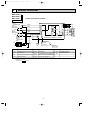
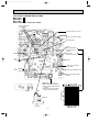
WIRING DIAGRAM
MSC-07RV - E4
MSC-09RV - E4
MSC-12RV - E4
MODELS WIRING DIAGRAM
INDOOR UNIT
TO OUTDOOR
TB
UNIT
L
CONNECTING
BRN
FOR
3
MUH OR
MXZ TYPE
N
12V
FOR
MU OR
MUX TYPE
12V
2
BRN
TAB12
RED
CN201
3
2
1
CN202
2
1
BLU
BLU
WHT
1
BLK
TRANS
F11
RT12
CN
111
RT11
CN
121
C11
SR141
BLK
GRY
YLW
BRN
WHT
RED
3
1
3
5
1
2
3
MF
4
5
6
CN211
ELECTRONIC CONTROL P.C. BOARD
5
GRN
CIRCUIT BREAKER
GRN/YLW
PE
SYMBOL
NR11
CN
101
LD103 CN
151
POWER
SUPPLY
CORD
~/N 220-240V
50Hz
T11
CN
112
NAME
MV
5
POWER MONITOR,
RECEIVER
P.C.BOARD
REMOTE
CONTROLLER
NAME
SYMBOL
SYMBOL
NAME
C11
INDOOR FAN CAPACITOR
NR11
VARISTOR
TB
TERMINAL BLOCK
F11
FUSE(3.15A)
RT11
ROOM TEMPERATURE THERMISTOR
T11
TRANSFORMER
MF
INDOOR FAN MOTOR(INNER FUSE)
RT12
INDOOR COIL THERMISTOR
MV
VANE MOTOR
SR141
SOLID STATE RELAY
NOTE:1. About the outdoor side electric wiring refer to the outdoor unit electric wiring diagram for servicing.
2. Use copper conductors only. (For field wiring)
3. Symbols below indicate.
/: Terminal block,
: Connector
13
SG79J412H01
OB252C-1.qxp
02.4.25 11:27 AM
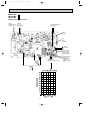
MU-07RV - E4
MU-09RV - E4
MU-12RV - E4
OUTDOOR UNIT
Page 14
MODELS WIRING DIAGRAM
TB2
2
FROM
INDOOR UNIT
CONNECTING
12V
WHT
1
52C
BLK
BRN
TB1
CIRCUIT BREAKER
52C
L
WHT
BRN
NO COM
N
POWER SUPPLY
~/N
220-240V
50Hz
PE
NAME
SYMBOL
COMPRESSOR CAPACITOR
C2
OUTDOOR FAN CAPACITOR
DSAR
C
WHT
BLU
GRN/YLW
C1
C2
RED
S
BLK
WHT 1 WHT
BLU 2 BLK
RED 3 RED
NAME
SYMBOL
C1
DSAR
MC
COMPRESSOR(INNER PROTECTOR)
MF
OUTDOOR FAN MOTOR(INNER FUSE)
MC
R
MF
SYMBOL
NAME
52C
COMPRESSOR CONTACTOR
TB1,TB2 TERMINAL BLOCK
SURGE ABSORBER
NOTE:1. About the indoor side electric wiring refer to the indoor unit electric wiring diagram for servicing.
2.Use copper conductors only. (For field wiring)
3. Symbols below indicate.
/: Terminal block,
: Connector
MODELS WIRING DIAGRAM
CN721
NR61
SR61
T61
N BLU
TAB20
CN711
WHT
1
BLK
2
RED
3
C65
52C
PE
4
GRN/YLW
NAME
SYMBOL
MF
CN661
SR62
BLK
CIRCUIT BREAKER TB1 BRN
L BRN
POWER SUPPLY
~/N
220-240V
50Hz
1
2
3
F61
N
RED
CN730
TB2
3
FROM
INDOOR UNIT
CONNECTING
12V
21S4
RT61
DSAR
MUH-07RV - E4
MUH-09RV - E4
MUH-12RV - E4
OUTDOOR UNIT
VG79B132H01
3
BLU
DEICER P.C.BOARD
C
WHT
C1
RED
MC
S
R
BLK
NAME
SYMBOL
NAME
SYMBOL
OUTDOOR FAN MOTOR(INNER FUSE) TB1,TB2 TERMINAL BLOCK
C1
COMPRESSOR CAPACITOR
MF
C65
OUTDOOR FAN CAPACITOR
NR61
VARISTOR
21S4
R.V. COIL
SURGE ABSORBER
RT61
DEFROST THERMISTOR
52C
COMPRESSOR CONTACTOR
DSAR
F61
FUSE(2A)
MC
COMPRESSOR(INNER PROTECTOR)
SR61, SR62 SOLID STATE RELAY
T61
TRANSFORMER
NOTE:1. About the indoor side electric wiring refer to the indoor unit electric wiring diagram for servicing.
2.Use copper conductors only. (For field wiring)
3. Symbols below indicate.
/: Terminal block,
: Connector
14
SG79B111H01
OB252C-1.qxp
02.4.25 11:27 AM
5
Page 15
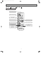
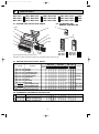
REFRIGERANT SYSTEM DIAGRAM
Unit:mm
MUH-07RV - E3 MUH-07RV - E4
MUH-09RV - E3 MUH-09RV - E4
MSC-07RV - E3 MSC-07RV - E4
MSC-09RV - E3 MSC-09RV - E4
INDOOR UNIT
(with heat insulator)
Indoor
heat
exchanger
Indoor coil
thermistor
RT12
OUTDOOR UNIT
Refrigerant pipe [ 9.52
Flared connection
4-way valve
Muffler
Defrost
thermistor
RT61
Stop valve
(with service
port)
Outdoor
heat
exchanger
Strainer
Room temperature
thermistor
RT11
Capillary tube
[3.0x[1.4x800 (2 pcs)
Compressor
Capillary tube
[3.0x[1.6x600(MUH-07)
[3.0x[1.6x400(MUH-09)
Flared connection
Check valve
R.V. coil
heating ON
cooling OFF
Strainer
Capillary tube
[3.0x[1.4x600(MUH-07)
[3.0x[1.4x550(MUH-09)
Stop valve
Refrigerant pipe [6.35
(with heat insulator)
Refrigerant flow in cooling
Refrigerant flow in heating
Unit:mm
MSC-12RV -
E3
MSC-12RV -
INDOOR UNIT
Indoor
heat
exchanger
Indoor coil
thermistor
RT12
MUH-12RV -
E4
Refrigerant pipe [12.7
(with heat insulator)
E3
MUH-12RV - E4
OUTDOOR UNIT
4-way valve
Muffler
Stop valve
(with service port)
Flared connection
Strainer
Defrost
thermistor
RT61
Room temperature
thermistor
RT11
Outdoor
heat
exchanger
Capillary tube
[3.0x[1.4x500(2pcs)
Compressor
Capillary tube
[3.0x[1.8x300
Flared connection
Strainer
Capillary tube
[3.0x[1.6x700
R.V. coil
heating ON
cooling OFF
Stop valve
Refrigerant flow in cooling
Refrigerant pipe [6.35
(with heat insulator)
Check
valve
15
Refrigerant flow in heating
OB252C-1.qxp
6
02.4.25 11:27 AM
Page 16
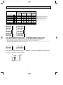
MICROPROCESSOR CONTROL
MSC-07RV - E4 MU-07RV - E4 MUH-07RV - E4
MSC-09RV - E4 MU-09RV - E4 MUH-09RV - E4
MSC-12RV - E4 MU-12RV - E4 MUH-12RV - E4
6-1. 11-1. COOL (
) OPERATION
1. Indoor fan speed control
Indoor fan operates continuously at the set speed by FAN SPEED CONTROL button regardless of thermostat’s OFF-ON.
In Auto the fan speed is as follows.
MSC-07RV MSC-09RV MSC-12RV -
MSC-07RV - E3
MSC-09RV - E3
E1
E2
MSC-12RV - E3
Fan speed
Initial temperature difference
Room temperature minus set temperature : 2 degrees or more································High
Room temperature minus set temperature : Between 1 and 2 degrees····················Med.
Room temperature minus set temperature : less than 1 degree································Low
MSC-07RV MSC-09RV MSC-12RV -
E1
E1
MSC-07RV MSC-09RV MSC-12RV -
E2
E2
2 deg.
1 deg. 1.7 deg.
4 deg.
E4
E4
E4
Fan speed
Initial temperature difference
Room temperature minus set temperature : 1.7 degrees or more·····························High
Room temperature minus set temperature : Between 1 and 1.7 degrees·················Med.
Room temperature minus set temperature : less than 1 degree································Low
7
Difference between room
temperature and set temperature during operation
Difference between room
temperature and set temperature during operation
3 deg.
1 deg. 1.7 deg.
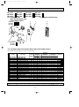
TROUBLESHOOTING
7-1. Trouble criterion of main parts
MSC-07RV - E4 MU-07RV - E4 MUH-07RV - E4
MSC-09RV - E4 MU-09RV - E4 MUH-09RV - E4
MSC-12RV - E4 MU-12RV - E4 MUH-12RV - E4
Check method and criterion
Part name
INNER FUSE
136I3 CUT OFF
Measure the resistance between the terminals with a tester.
(Coil wiring temperature10°C ~ 30°C)
Motor part
Indoor fan
motor(MF)
Figure
Color of
lead wire
Normal
MSC-07/09RV- E4
Abnormal
MSC-12RV- E4
WHT-BLK
396 ~ 430Ω
396 ~ 430Ω
BLK-RED
320 ~ 348Ω
320 ~ 348Ω
WHT
RED
FUSE
Open or
short-circuit
BLK
YLW
GRY
BRN
Measure the resistance between the terminals with a tester.
(Coil wiring temperature –10°C ~ 40°C)
Outdoor fan
motor(MF)
INNER FUSE
163I3 CUT OFF
Color of
lead wire
MAIN
Normal
MU-07/09RV- E4
MU-12RV- E4
WHT-BLK
311 ~ 381 Ω
265 ~ 325Ω
BLK-RED
283 ~ 347Ω
292 ~ 359Ω
Abnormal
AUX.
FUSE
Open or short-circuit
BLK
Color of
lead wire
Normal
MUH-07/09RV- E4
MUH-12RV- E4
WHT-BLK
311 ~ 381 Ω
265 ~ 325Ω
BLK-RED
283 ~ 347 Ω
292 ~ 359 Ω
16
Abnormal
Open or short-circuit
RED WHT
OB252C-1.qxp
02.4.25 11:27 AM
Page 17
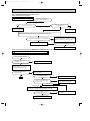
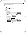
When OPERATION INDICATOR lamp flashes 3-time.
Indoor fan motor doesn’t operate.
A Check of indoor fan motor
Turn OFF the power supply.
Check connector CN211 visually.
Yes
No
Is soldered point of the connector
correctly soldered?
Are lead wires connected?
No
Yes
Re-connect the lead wires.
Re-solder it.
Disconnect lead wires from connector CN211 on indoor electronic control P.C. board.
Measure resistance between lead wires No.1 and No.5 and then No.3 and No.5.
Is resistance 0 (short circuit) or ∞ (open circuit)?
No
(others)
Yes ( 0 or ∞ )
Turn ON the power supply. Stop it if the unit operate. Insert screwdriver into air outlet to rotate
indoor fan motor slowly for 1 revolution or over, and
measure voltage No.2(+) and No.3(-) on CN121.
No
Repair or replace the indoor fan motor.
Does voltage repeat 0V DC and 5V DC?
Yes
Replace the indoor electronic control P.C. board.
Indoor unit operates by pressing the EMERGENCY OPERATION switch, but doesn’t operate with the remote controller.
B Check of remote controller and receiver P.C. board
wCheck the remote controller is exclusive for this air conditioner.
Switch on the remote controller.
No
Is LCD display on the remote controller displayed?
Replace the batteries.
(not clear)
Yes
Remove batteries, then set them back and
press the RESET button. Check if the unit
operates with the remote controller.
Does the unit operate with the
remote controller?
No
Turn on a radio to AM and press switch on
the remote controller.
Yes
No
Is noise heard from radio?
Replace the remote controller.
Ok
Yes
Are there any fluorescent lights of
inverter or rapid-start type within
the range of 1m?
No
MSC-07/09/12RV-
Yes
MSC-07/09/12RV-
E1
• Re-install the unit away from lights.
• Attach a filter on receiving part.
,
E2
,
E3
E4
Measure the voltage between receiver P.C. board connector CN302
No.3(–)and No.5(+) when the remote controller button is pressed.
Yes
Is the voltage approx. 4V DC?
No(5V or 0V DC)
Replace the receiver P.C. board.
17
Replace the indoor electronic control
P.C. board.
OB252C-1.qxp
02.4.25 11:27 AM
Page 18
The unit doesn’t operate with the remote controller.
Also, the OPERATION INDICATOR lamp doesn’t light up by pressing the EMERGENCY OPERATION switch.
C Check of indoor electronic control P.C. board
Check the both “parts side” and “pattern
side” of indoor electronic control P.C.
board visually.
Turn OFF the power supply.
Remove indoor fan motor connector CN211 and
vane motor connector CN151 from the indoor electronic
control P.C. board and turn ON the power supply.
Does the unit operate with the remote controller?
No
Does the OPERATION INDICATOR lamp light up
by pressing the EMERGENCY OPERATION switch?
Yes
Turn OFF the
power supply.
Replace the vane
motor.
Turn OFF the
power supply.
Replace the fuse.
Yes
Yes
Is winding
resistance of
vane motor 0 "?
No
Be sure to check both resistances.
Is winding
resistance of
fan motor 0 "?
Is fuse(F11) blown?
Replace the indoor
electronic control
P.C. board.
Be sure to check both fuse
and varistor in any case.
Is varistor(NR11) burnt?
No
Yes
Yes
Replace the fan
motor.
No
Replace the varistor.
18
No
OB252C-1.qxp
02.4.25 11:27 AM
Page 19
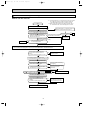
Compressor and / or outdoor fan motor doesn’t operate.
D Check of outdoor unit
<MU-07/09/12RV>
Start
Is the switch SW2-2 on the
indoor electronic control
P.C. board set to MU type?
No
Change the switch SW-2-2
on the indoor electronic control
P.C. board to MU type.
Yes
Operate the unit in COOL mode by pressing the
EMERGENCY OPERATION switch.
3-minute time delay works.
Test run operation operates for 30 minutes.
Compressor
doesn't operate.
Is there 220-240V AC
Yes
between 1–2 on the outdoor
terminal block (TB2)?
No
Check the indoor electronic
control P.C. board, and rectify
the indoor and outdoor
connecting wire.
Is there 220-240V AC between L–N
on the outdoor terminal block (TB1)?
No
Check the power supply, and
rectify the connecting wire.
Yes
Is there 220-240V AC between COM
on the compressor contactor (52C) and
N on the outdoor terminal block (TB1)?
Yes
No
Replace the compressor
contactor (52C).
Check the compressor and
compressor contactor, and
rectify the connecting wire.
Outdoor fan motor
doesn't operate.
MU-07/09/12RV- E1 , E2 , E3
Is fuse "F" (2A) blown?
No
Is there 12V DC between
1–2 on the outdoor
terminal block (TB2)?
No
Check the indoor electronic
control P.C. board, and rectify
the indoor and outdoor
connecting wire.
Yes
Yes
Replace the fuse "F" (2A).
Is there 220-240V AC between L–N No
on the outdoor terminal block (TB1)?
Yes
Is there 220-240V AC between COM
No
on the compressor contactor (52C) and
N on the outdoor terminal block(TB1)?
Yes
Check the outdoor fan motor
and outdoor fan capacitor,
and rectify the connecting wire.
19
Check the power supply, and
rectify the connecting wire.
Replace the compressor
contactor (52C).
OB252C-1.qxp
02.4.25 11:27 AM
Page 20
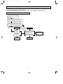
Compressor and / or outdoor fan motor doesn’t operate.
D Check of outdoor unit
<MUH-07/09/12RV>
Start
Is the switch SW2-2 on the No
indoor electronic control
P.C. board set to MUH type?
Change the switch SW-2-2
on the indoor electronic control
P.C. board to MUH type.
Yes
Operate the unit in COOL or HEAT mode by pressing the
EMERGENCY OPERATION switch.
3-minute time delay works.
Test run operation operates for 30 minutes.
Compressor
doesn't operate.
Rectify the indoor and
outdoor connecting wire.
No
Is there 5V DC between J8 – –J9 +
(MUH-07/09/12RV- E1 , E2 , E3 )/
J205 + –J101– (MUH-07/09/12RV- E4 )
on the deicer P.C. board?
Yes
No
Is there 220-240V AC between 4
on the compressor contactor (52C) and
TAB20 on the deicer P.C. board?
Yes
No
Yes
Replace the
deicer P.C. board.
Is there 220-240V AC between
3 on the compressor contactor
(52C) and N on the outdoor
terminal block (TB1)?
No
Is there 220-240V AC between L–N
on the outdoor terminal block (TB1)?
Rectify the connecting wire.
Replace the
deicer P.C. board.
Yes
Check the compressor and compressor
capacitor, and rectify the connecting wire.
Outdoor fan motor
doesn't operate.
Is there 5V DC between J8 – –J9 +
(MUH-07/09/12RV- E1 , E2 , E3 )/
J205 + –J101– (MUH-07/09/12RV- E4 )
on the deicer P.C. board?
Yes
Check the outdoor fan motor
and rectify the connecting
wire.
Rectify the indoor and
outdoor connecting wire.
No
No
Is there 220-240V AC between 4 on
the compressor contactor (52C) and
TAB 20 on the deicer P.C. board?
Yes
Replace the
deicer P.C. board.
20
No
Is there 220-240V AC between L–N
on the outdoor terminal block (TB1)?
Yes
Rectify the connecting wire.
OB252C-1.qxp
02.4.25 11:27 AM
Page 21
E How to check mis-wiring and serial signal error
Outdoor unit does not work.
w 1 Set the switch(SW2-2) on indoor electronic control P.C. board to
MU or MUX type, when the outdoor unit is MU or MUX type.
If the setting is MUH or MXZ type, the unit does not work.
Start
w 2 Short circuit of JPG and JPS on the indoor electronic control
P.C. board enables self -check to be displayed in 3 seconds.
Turn OFF the power supply(indoor/outdoor unit).
Set the switch(SW2-2) on the indoor electronic
control P.C. board to MU or MUX type. w1
No
Is the outdoor unit "MUH or MXZ" type?
Yes
•Turn ON the power supply(indoor/outdoor unit).
•Press once EMERGENCY OPERATION switch.
Yes
Serial signal error is indicated.
(0.5-sec. ON, 2.5-sec. OFF)
3 min. later, what self-check result is
displayed on OPERATION INDICATOR
lamp on indoor unit? w 2
Does the unit operate?
Mis-wiring is indicated.
(0.5-sec. ON, 0.5-sec. OFF)
Yes
Make them sure.
No
Refer to the
"Instruction of
troubleshooting."
Is this mis-wiring, poor contact,
or disconnection of wire?
No
1. Turn OFF the power supply(indoor/outdoor unit) and disconnect indoor and outdoor connecting wire on indoor side.
2. Short-circuit between indoor terminal block N and 3.
3. Turn ON the power supply(indoor unit) and press once EMERGENCY OPERATION switch.
Is there 20V DC between both ends of
R132 on indoor electronic control P.C.
board ?
( By tester, the stylus is between 0 ~ 20V. )
No
Replace the indoor electronic
control P.C. board.
No
Refer to T Check of mis-wiring
or mis-piping.
No
Check the outdoor power supply,
power supply cord and
connection.
Yes
•Turn OFF the power supply(indoor unit).
•Connect ON indoor and outdoor connecting wire.
Turn ON the power supply(outdoor unit).
Is the outdoor unit "MUH" type?
Yes
Is there 220-240V AC between outdoor
terminal block L-N (TB1)?
Yes
Is there 5V DC between J8 - –J9 + (MUH-07/09/12RV- E1 , E2 , E3 )/
J205 + –J101 - (MUH-07/09/12RV- E4 ) on the deicer P.C. board?
Yes
No
Replace the deicer P.C. board.
Turn ON the power supply(indoor unit).
During EMERGENCY OPERATION,
is there 10V DC between both ends
of R601?
(By tester, the stylus is between 5 ~10V)
Yes
Replace the deicer P.C. board.
21
No
Make the wiring between CN730
on the deicer P.C. board and
outdoor terminal block correct.
Ok
OB252C-1.qxp
02.4.25 11:27 AM
Page 22
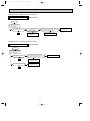
Compressor and / or outdoor fan motor doesn’t stop.
V Check of outdoor unit
<MU-07/09/12RV>
Start
Turn OFF the power supply.
After 1 minute, turn ON
power supply again.
Does compressor or
outdoor fan motor stop?
No
Yes
Is there 12V DC between
1–2 on the outdoor
terminal block (TB2)?
Yes
No
Is there 220-240V AC between COM on
Yes
the compressor contactor (52C) and N on
the outdoor terminal block (TB1)?
No
Replace the indoor
electoronic control
P.C. board.
Ok
Rectify the connecting wire.
Compressor and / or outdoor fan motor doesn’t stop.
V Check of outdoor unit
<MUH-07/09/12RV>
Start
Turn OFF the power supply.
After 1 minute, turn ON
power supply again.
Does compressor stop?
No
Yes
Ok
Is there 220-240V AC between 3 on
the compressor contactor (52C) and N on
the outdoor terminal block (TB1)?
Yes
Replace the
deicer P.C. board.
Does outdoor fan motor stop?
No
Replace the
deicer P.C. board.
Yes
Ok
22
No
Rectify the connecting wire.
Replace the compressor
contactor(52C).
OB252C-1.qxp
02.4.25 11:27 AM
Page 23
When OPERATION INDICATOR lamp flashes 6-time.
Thermistors in the outdoor unit are abnormal.
W Check of outdoor thermistor
<MUH-07/09/12RV>
Start
Turn OFF the
power supply.
Replace the deicer P.C.
board.
Defrost thermistor (RT61)
Measure
resistance
between CN 661
1 and 2.
Does the resistance
of thermistor have
the characteristics ?
Yes
No
Re-connect CN661.
Turn ON the power
supply and press
the EMERGENCY
OPERATION
switch.
No
Does the unit operate
10 minutes or more?
Yes
Ok ❈
Replace the
thermistor.
❈ Defective contact of the connector is considered.
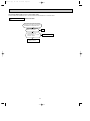
Unit operates COOL mode even if it is set to HEAT mode.
w First, measure the resistance of R.V. coil to confirm it is disconnected or is not short-circuit.
X Check of R.V. coil
<MUH-07/09/12RV>
Turn ON the power supply and operate
the indoor unit in HEAT mode by pressing
the EMERGENCY OPERATION switch.
After 3 minutes, does the unit
operate in COOL mode?
No
Ok
Yes
Is there 220-240V AC
between CN7211 – 2 on the
deicer P.C. board?
Yes
Replace the R.V. coil.
23
No
Replace the
deicer P.C. board
OB252C-1.qxp
02.4.25 11:27 AM
Page 24
Unit operates HEAT mode even if it is set to COOL mode.
w First, measure the resistance of R.V. coil to confirm it is disconnected or is not short-circuit.
X Check of R.V. coil
<MUH-07/09/12RV>
Turn ON the power supply and operate
the indoor unit in COOL mode by pressing
the EMERGENCY OPERATION switch.
Yes
After 3 minutes, does the unit
operate in HEAT mode?
No
Ok
Yes
Is there 220-240V AC
between CN7211 – 2 on the
deicer P.C. board?
No
Replace the R.V. coil.
Yes
Replace the
deicer P.C. board.
24
OB252C-1.qxp
02.4.25 11:28 AM
Page 25
TEST POINT DIAGRAM AND VOLTAGE
MSC-07RV - E4
MSC-09RV - E4
MSC-12RV - E4
Indoor electronic control P.C. board
}
Power supply input
220-240V AC
Fuse(F11) 250V AC 3.15A
}
Fan motor power supply
Varistor (NR11)
CN111
Room temperature
thermistor (RT11)
CN112
Indoor coil
thermistor (RT12)
CN201
}
12V
DC
+
CN121
Timer short mode point
(JPS, JPG)
JPGND
J205
Emergency operation switch
+
Vane motor power supply
(CN151)
CN302
R132
SW2 (Refer to page 121 of
OB227 REVISED EDITION-B.)
1 sets the Auto restart function
ON/ OFF.
2 switches over MU and MUX
type/ MUH and MXZ type.
Resistance(k")
}
5V
DC
0~20V DC
P.C.board
25
OB252C-1.qxp
02.4.25 11:28 AM
Page 26
MUH-07RV - E4
MUH-09RV - E4
MUH-12RV - E4
Outdoor deicer P.C. board
CN721
CN711
Outdoor fan motor R.V. coil
220-240V AC
220-240V AC
}
}
}
Power supply input
220-240V AC
NR61
Varistor
F61
Fuse
2A/250V
+
--
}
R601
5~10VDC
Defrost interval
time short pin
(JPDS, JPSG)
(Refer to page 5.)
}
CN661 1-2
Defrost thermistor RT61
5V DC
J205 +
J101 -12V DC
J204 +
J101 --
26
}
Jumper wire for
change in
defrost setting
(JRF,JRG)
(Refer to page
5.)
OB252C-1.qxp
02.4.25 11:28 AM
8
Page 27
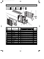
PARTS LIST
MSC-07RV - E1 (WH) MSC-07RV - E2 (WH) MSC-07RV - E3 (WH) MSC-07RV - E4 (WH)
MSC-09RV - E1 (WH) MSC-09RV - E2 (WH) MSC-09RV - E3 (WH) MSC-09RV - E4 (WH)
MSC-12RV - E1 (WH) MSC-12RV - E2 (WH) MSC-12RV - E3 (WH) MSC-12RV - E4 (WH)
8-2. ACCESSORY AND
REMOTE CONTROLLER
8-1. INDOOR UNIT STRUCTURAL PARTS
1 (W1)
12
11
2
13
10
3
9 (W2)
4
8 (W2)
5
6
MSC-07RV MSC-09RV MSC-12RV -
7 (W1)
(W1) These figures show about MSC-12RV.
MSC-07RV MSC-09RV MSC-12RV -
E2
E2
E2
E3
E4
E3
E4
E3
E4
(W2) Refer to OB227 REVISED EDITION-B 16. OPTIONAL PARTS. (See page 184 )
8-1. INDOOR UNIT STRUCTURAL PARTS
Q'ty/unit
MSC-09RV-
Symbol
No.
Part No.
E02
E02
E02
E02
E02
E02
E02
E02
E02
409
411
409
424
409
424
408
408
410
Part Name
234
234
976
000
067
010
142
100
100
BOX(WH)
1
BOX(WH)
2
CORNER BOX (LEFT)
3
FRONT PANEL(WH)
4
SCREW CAP(WH)
5
GRILLE(WH)
6
CATCH
AIR FILTER
7
AIR FILTER
8
DEODORIZING FILTER
9
AIR CLEANING FILTER
10 E02 409 975 CORNER BOX (RIGHT)
11 E02 408 970 INSTALLATION PLATE
in Wiring
MSC-07RVE1
E2
E3
E4
E1
E2
E3
MSC-12RV-
E4
E1
Diagram (WH) (WH) (WH) (WH) (WH) (WH) (WH) (WH) (WH)
1 1 1 1 1
1
1 1
1
1 1 1 1 1
1
1
1 1
1 1 1 1 1
1
1
1 1
2
2
2
2
2
2
2
2
2
1 1 1 1 1
1
1
1 1
3 3 3 3 3
3
3
3 3
2 2 2 2 2
2
2 2
2
1
1
1
1
1
1
1
1
1
1 1 1 1 1
1
1
1 1
1 1 1 1 1
1
1
1 1
1 1 1 1 1
1
1
1 1
E2
E3
E4
(WH) (WH) (WH)
1
1
1
2
1
3
1
1
1
2
1
3
1
1
1 Including No.4,5,6
2 2PCS/SET
1
3 3PCS/SET
2
1
1
1
1
2
1
1
1
1
2
1 MAC-1800DF
1 MAC-1300FT
1
1
1
1
1
1
8-2. ACCESSORY AND REMOTE CONTROLLER
E02
E02
E02
13
E02
12
141
527
504
583
083
083
426
426
REMOTE CONTROLLER HOLDER
REMOTE CONTROLLER HOLDER
REMOTE CONTROLLER
REMOTE CONTROLLER
1
1
1
1
1
1
1
1
1
1
1
1
27
1
1
1
1
1
Remarks
OB252C-1.qxp
02.4.25 11:28 AM
Page 28
MSC-07RV - E1 (WH) MSC-07RV - E2 (WH) MSC-07RV - E3 (WH) MSC-07RV - E4 (WH)
MSC-09RV - E1 (WH) MSC-09RV - E2 (WH) MSC-09RV - E3 (WH) MSC-09RV - E4 (WH)
MSC-12RV - E1 (WH) MSC-12RV - E2 (WH) MSC-12RV - E3 (WH) MSC-12RV - E4 (WH)
8-4. INDOOR UNIT HEAT EXCHANGER
8-3. INDOOR UNIT ELECTRICAL PARTS
AND FUNCTIONAL PARTS
18 (W)
17
SLEEVE
BEARING
1
16
14
15
13
2
ROOM TEMPERATURE
THERMISTOR
3
12
11
19
4
10
20
5
FUSE
6
VARISTOR
7
8
(W)These figures show about MSC-12RV.
9
8-3. INDOOR UNIT ELECTRICAL PARTS AND FUNCTIONAL PARTS
No.
1
2
3
4
5
6
7
8
9
10
11
12
13
14
15
16
17
Part No.
E02
E02
E02
E02
E02
E02
E02
E02
E02
E02
E02
E02
E02
E02
E02
E02
E02
E02
E02
E02
E02
E02
E02
E02
E02
E02
E02
E02
E02
E02
E02
001
408
409
409
409
127
336
408
424
504
583
691
425
505
584
692
426
506
693
408
693
408
151
665
424
691
151
665
408
408
408
504
702
235
040
041
382
385
034
452
452
452
452
452
452
452
452
452
452
452
303
303
308
300
300
375
375
505
505
307
302
509
Part Name
Symbol
in Wiring
Diagram
SLEEVE BEARING
DRAIN HOSE
NOZZLE (WH)
VANE UPPER (WH)
VANE LOWER (WH)
F11
FUSE
NR11
VARISTOR
VANE MOTOR SUPPORT SET
ELECTRONIC CONTROL P.C.BOARD
ELECTRONIC CONTROL P.C.BOARD
ELECTRONIC CONTROL P.C.BOARD
ELECTRONIC CONTROL P.C.BOARD
ELECTRONIC CONTROL P.C.BOARD
ELECTRONIC CONTROL P.C.BOARD
ELECTRONIC CONTROL P.C.BOARD
ELECTRONIC CONTROL P.C.BOARD
ELECTRONIC CONTROL P.C.BOARD
ELECTRONIC CONTROL P.C.BOARD
ELECTRONIC CONTROL P.C.BOARD
MV
VANE MOTOR
MV
VANE MOTOR
ROOM TEMPERATURE THERMISTOR RT11
MF
INDOOR FAN MOTOR
MF
INDOOR FAN MOTOR
TB
TERMINAL BLOCK
TB
TERMINAL BLOCK
FAN MOTOR RUBBER MOUNT
FAN MOTOR RUBBER MOUNT
RT12
INDOOR COIL THERMISTOR
LINE FLOW FAN
BEARING MOUNT
Q'ty/unit
MSC-07RV
E1
E2
E3
MSC-09RV
E4
E1
E2
E3
MSC-12RV
E4
E1
E2
E3
Remarks
E4
(WH) (WH) (WH) (WH) (WH) (WH) (WH) (WH) (WH) (WH) (WH) (WH)
1
1
1
1
1
1
1
1
1
1
1
1
1
1
1
1
1
1
1
1
1
1
1
1
1
1
1
1
1
1
1
1
1
1
1
1
1
1
1
1
1
1
1
1
1
1
1
1
1
1
1
1
1
1
1
1
1
1
1
1
1
1
1
1
1
1
1
1
1
1
1
1
1
1
1
1
1
1
1
1
1
1
1
1
1
1
1
1
1
1
1
1
1
1
1
1
1
1
1
1
1
1
1
1
1
1
1
1
1
1
1
1
1
1
1
1
1
1
1
1
1
1
1
1
1
1
1
1
1
1
1
1
1
1
1
1
1
1
1
1
1
1
2
2
2
1
2
1
1
1
1
1
1
1
1
1
1
1
1
1
1
1
1
1
1
1
1
1
1
1
1
1
1
1
1
1
1
2
2
2
1
2
1
1
1
1
1
1
1
1
1
2
1
1
1
1
1
1
1
1
1
1
2
2
1
1
1
1
1
1
1
1
1
2
1
1
1
1
1
1
1
3.15A
AUTO RESTART
AUTO RESTART
AUTO RESTART
AUTO RESTART
AUTO RESTART
AUTO RESTART
AUTO RESTART
AUTO RESTART
AUTO RESTART
AUTO RESTART
AUTO RESTART
RC4V19RC4V19-
2PCS/SET
2PCS/SET
8-4. INDOOR UNIT HEAT EXCHANGER
E02
18 E02
E02
19 E02
E02
20 E02
408
410
515
151
155
151
620
620
620
666
666
667
INDOOR HEAT EXCHANGER
INDOOR HEAT EXCHANGER
INDOOR HEAT EXCHANGER
UNION(GAS)
UNION(GAS)
UNION(LIQUID)
1
1
1
1
1
28
1
1
1
1
1
1
1
1
1
1
1
1
1
1
{9.52
{12.7
{6.35
OB252C-1.qxp
02.4.25 11:28 AM
Page 29
MU-07RV - E1 MU-07RV - E2 MU-07RV - E3 MU-07RV - E4
MU-09RV - E1 MU-09RV - E2 MU-09RV - E3 MU-09RV - E4
MU-12RV - E1 MU-12RV - E2 MU-12RV - E3 MU-12RV - E4
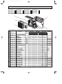
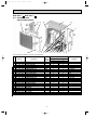
8-5. OUTDOOR UNIT STRUCTURAL PARTS
12
11
10
9
1
2
3
5
4
6
7
8
Part number that is circled is not shown in the illustration.
No.
1
2
3
4
5
6
7
8
9
10
11
12
13
Part No.
E02
E02
E02
E02
E02
E02
E02
E02
E02
E02
E02
E02
E02
E02
E02
E02
E02
E02
E02
E02
E02
E02
E02
336
336
336
437
589
438
408
141
594
336
075
339
340
339
340
339
336
339
440
336
336
339
412
630
232
521
900
900
900
900
900
900
506
506
290
290
661
661
662
245
233
233
515
297
936
936
Part name
OUTDOOR HEAT EXCHANGER
CABINET
GRILLE(OUT)
COMPRESSOR
COMPRESSOR
COMPRESSOR
COMPRESSOR
COMPRESSOR
COMPRESSOR
COMPRESSOR RUBBER SET
COMPRESSOR RUBBER SET
BASE
BASE
STOP VALVE(GAS)
STOP VALVE(GAS)
STOP VALVE(LIQUID)
SERVICE PANEL
BACK PANEL
BACK PANEL
MOTOR SUPPORT
TOP PANEL
CAPILLARY TUBE
CAPILLARY TUBE
Symbol
in Wiring
Diagram
MC
MC
MC
MC
MC
MC
Q'ty/unit
MU-09RV-
MU-07RV-
MU-12RV-
Remarks
E1
E2
E3
E4
E1
E2
E3
E4
E1
E2
E3
E4
1
1
1
1
1
1
1
1
1
1
1
1
1
1
1
1
1
1
1
1
1
1
1
1
1
1
1
1
1
1
1
1
1
1
1
1
1
1
1
1
1
3
3
3
RH-135VGCT
RH-130VGCT
RH-145VGCT
RH-140VGCT
RH-231VHAT
1 RH-220VHAT
3RUBBERS/SET
3 3RUBBERS/SET
1
1
1
1
1
1
1
1
1
1
1
1
1
{9.52
1 {12.7
1 {6.35
1
1
1
1
1
1
1
1
1
1
1
1
1
1
1
1
{3.0x{1.4x600
1 {3.0x{1.6x600
1
1
1
1
1
1
3
3
3
3
3
3
3
3
1
1
1
1
1
1
1
1
1
1
1
1
1
1
1
1
1
1
1
1
1
1
1
1
1
1
1
1
1
1
1
1
1
1
1
1
1
1
1
1
1
1
1
1
1
1
1
1
1
1
1
1
1
1
1
1
1
1
1
1
1
1
1
1
29
OB252C-1.qxp
02.4.25 11:28 AM
Page 30
MU-07RV - E1 MU-07RV - E2 MU-07RV - E3 MU-07RV - E4
MU-09RV - E1 MU-09RV - E2 MU-09RV - E3 MU-09RV - E4
MU-12RV - E1 MU-12RV - E2 MU-12RV - E3 MU-12RV - E4
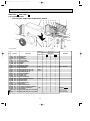
8-7. REMOTE CONTROLLER
8-6. OUTDOOR UNIT
ELECTRICAL PARTS AND
FUNCTIONAL PARTS
MU-07RV MU-09RV MU-12RV -
E1
E2
E3
E1
E2
E3
E1
E2
E3
6
10
5
2
1
3
MU-07RV MU-09RV MU-12RV -
4
E4
E4
E4
8-6. OUTDOOR UNIT ELECTRICAL PARTS AND FUNCTIONAL PARTS
Part numbers that are circled are not shown in the illustration.
No.
1
2
3
4
5
6
7
8
9
Part No.
E02
E02
E02
E02
E02
E02
E02
E02
E02
E02
E02
E02
E02
E02
E02
E02
E02
E02
E02
E02
336
665
437
676
439
677
095
661
664
085
694
079
696
437
466
438
001
466
095
128
501
501
301
301
301
301
350
351
351
353
353
353
353
374
375
374
340
340
382
383
Part name
Symbol
in Wiring
Diagram
PROPELLER FAN
PROPELLER FAN
OUTDOOR FAN MOTOR
MF
OUTDOOR FAN MOTOR
MF
OUTDOOR FAN MOTOR
MF
OUTDOOR FAN MOTOR
MF
OUTDOOR FAN CAPACITOR
C2
OUTDOOR FAN CAPACITOR
C2
OUTDOOR FAN CAPACITOR
C2
COMPRESSOR CAPACITOR
C1
COMPRESSOR CAPACITOR
C1
COMPRESSOR CAPACITOR
C1
COMPRESSOR CAPACITOR
C1
TERMINAL BLOCK
TB1
TERMINAL BLOCK
TB1
TERMINAL BLOCK
TB2
COMPRESSOR CONTACTOR 52C
COMPRESSOR CONTACTOR 52C
FUSE
F
SURGE ABSORBER
DSAR
Q'ty/unit
MU-09RV-
MU-07RVE1
E2
E3
1
1
1
E4
E1
E2
E3
1
1
1
1
1
1
1
MU-12RVE4
E1
E2
E3
1
1
1
1
1
1
1
1
1
1
1
1
1
1
1
1
1
1
1
1
1
1
1
1
1
1
1
1
1
1
1
1
1
1
1
1
1
1
1
1
1
1
1
1
1
1
1
1
1
1
1
1
1
1
1
1
1
1
1
1
1
1
1
1
1
1
1
1
1
1
1
1
1
1
1
1
1
1
1
1
1
1
1
1
1
1
1
1
1
1
1
8-7. REMOTE CONTROLLER
10 E02 408 426
REMOTE CONTROLLER
Remarks
E4
1
30
1
1
1
1
RA6V23RA6V23RA6V33RA6V331.5+ /440V AC
1.5+ /440V AC
2.0+ /440V AC
25+ /440V AC
25+ /440V AC
30+ /440V AC
30+ /440V AC
3P
3P
2P
1
250V/ 2A
1
OB252C-2.qxp
02.4.25 11:28 AM
MUH-07RV - E1
MUH-09RV - E1
MUH-12RV - E1
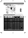
8-8. OUTDOOR
Page 31
MUH-07RV - E2 MUH-07RV - E3 MUH-07RV - E4
MUH-09RV - E2 MUH-09RV - E3 MUH-09RV - E4
MUH-12RV - E2 MUH-12RV - E3 MUH-12RV - E4
UNIT STRUCTURAL PARTS
13
12
1
11
2
3
10
4
Part numbers that are circled are not shown in the illustration.
No.
1
2
3
4
5
6
7
8
9
10
11
12
13
14
15
Part No.
E02
E02
E02
E02
E02
E02
E02
E02
E02
E02
E02
E02
E02
E02
E02
E02
E02
E02
E02
E02
E02
E02
E02
E02
E02
E02
E02
E02
E02
E02
E02
E02
440
442
336
336
164
589
128
593
141
594
336
075
339
340
339
340
139
444
336
440
336
442
336
159
156
339
441
412
134
134
442
154
630
630
232
521
900
900
900
900
900
900
506
506
290
290
661
661
662
961
245
233
515
515
297
936
936
936
936
936
937
936
936
642
Part name
OUTDOOR HEAT EXCHANGER
OUTDOOR HEAT EXCHANGER
CABINET
GRILLE(OUT)
COMPRESSOR
COMPRESSOR
COMPRESSOR
COMPRESSOR
COMPRESSOR
COMPRESSOR
COMPRESSOR RUBBER SET
COMPRESSOR RUBBER SET
BASE
BASE
STOP VALVE(GAS)
STOP VALVE(GAS)
STOP VALVE(LIQUID)
4-WAY VALVE
SERVICE PANEL
BACK PANEL
MOTOR SUPPORT
MOTOR SUPPORT
TOP PANEL
CAPILLARY TUBE
CAPILLARY TUBE
CAPILLARY TUBE
CAPILLARY TUBE
CAPILLARY TUBE
CAPILLARY TUBE
CAPILLARY TUBE
CAPILLARY TUBE
CHECK VALVE
Symbol
in Wiring
Diagram
MC
MC
MC
MC
MC
MC
5
6
7
8
Q'ty/unit
MUH-09RV-
MUH-07RVE1
E2
E3
E4
E1
E2
E3
E4
1
1
1
1
1
1
1
1
1
1
1
1
1
1
1
1
1
1
1
1
1
1
1
1
1
1
1
1
1
9
MUH-12RV-
E1
E2
E3
E4
1
1
1
1
1
1
1
1
1
1
1
1
3
3
3
RH-135VGHT
RH-130VGCT
RH-174VGHT
RH-165VGCT
RH-231VHAT
1 RH-220VHAT
3RUBBERS/SET
3 3RUBBERS/SET
1
1
1
1
1
1
1
1
1
1
1
1
1
1
1
1
1
1
1
{9.52
1 {12.7
1 {6.35
1
1
1
1
1
1
1
1
1
1
1
2
2
2
1
1
1
1
1
1
1
1
1
1
1
1
1
1
1
3
3
3
3
1
1
1
1
1
1
1
1
1
1
1
1
1
1
2
1
1
1
31
1
1
1
1
1
1
2
1
1
1
1
1
1
1
1
1
1
1
1
1
1
2
1
2
1
1
1
1
1
1
3
3
1
1
1
3
1
1
1
1
1
1
1
1
1
1
1
1
1
1
1
1
2
1
2
3
1
1
1
1
1
1
2
1
1
1
1
1
1
2
1
1
1
1
1
1
1
1
1
1
1
1
Remarks
{3.0x{1.4x800
2 {3.0x{1.4x500
{3.0x{1.4x600
{3.0x{1.4x550
{3.0x{1.6x600
{3.0x{1.6x400
1 {3.0x{1.6x700
1 {3.0x{1.8x300
1
OB252C-2.qxp
02.4.25 11:28 AM
Page 32
MUH-07RV - E1 MUH-07RV - E2 MUH-07RV - E3 MUH-07RV - E4
MUH-09RV - E1 MUH-09RV - E2 MUH-09RV - E3 MUH-09RV - E4
MUH-12RV - E1 MUH-12RV - E2 MUH-12RV - E3 MUH-12RV - E4
8-10. ACCESSORY AND
8-9. OUTDOOR UNIT
REMOTE CONTROLLER
ELECTRICAL PARTS AND
FUNCTIONAL PARTS
MUH-07RV MUH-09RV MUH-12RV -
E1
E2
E3
E1
E2
E3
E1
E2
E3
8
7
12
6
2
14
13
1
3
MUH-07RV MUH-09RV MUH-12RV -
5
4
E4
E4
E4
8-9. OUTDOOR UNIT ELECTRICAL PARTS AND FUNCTIONAL PARTS
Part numbers that are circled are not shown in the illustration.
No.
1
2
3
4
5
6
7
8
9
10
11
Part No.
E02
E02
E02
E02
E02
E02
E02
E02
E02
E02
E02
E02
E02
E02
E02
E02
E02
E02
E02
E02
E02
E02
E02
E02
E02
336
665
440
671
442
672
085
694
079
696
440
679
699
128
437
466
440
697
289
697
440
699
440
095
085
501
501
301
301
301
301
353
353
353
353
451
451
451
383
374
375
374
374
310
310
310
310
490
382
385
Part name
Symbol
in Wiring
Diagram
PROPELLER FAN
PROPELLER FAN
OUTDOOR FAN MOTOR
MF
OUTDOOR FAN MOTOR
MF
OUTDOOR FAN MOTOR
MF
OUTDOOR FAN MOTOR
MF
COMPRESSOR CAPACITOR
C1
COMPRESSOR CAPACITOR
C1
COMPRESSOR CAPACITOR
C1
COMPRESSOR CAPACITOR
C1
DEICER P.C. BOARD
DEICER P.C. BOARD
DEICER P.C. BOARD
SURGE ABSORBER
DSAR
TERMINAL BLOCK
TB1
TERMINAL BLOCK
TB1
TERMINAL BLOCK
TB2
TERMINAL BLOCK
TB2
DEFROST THERMISTOR
RT61
DEFROST THERMISTOR
RT61
DEFROST THERMISTOR
RT61
DEFROST THERMISTOR
RT61
R. V. COIL
21S4
FUSE
F61
VARISTOR
NR61
Q'ty/unit
MUH-09RV-
MUH-07RVE1
E2
E3
1
1
1
E4
E1
E2
E3
1
1
1
1
1
1
1
1
1
1
1
1
1
1
1
1
1
1
1
1
1
1
1
1
1
1
1
1
1
1
1
1
1
1
1
1
1
1
1
1
1
1
1
1
1
1
1
1
1
1
1
1
1
1
1
1
1
1
1
1
1
1
1
1
1
1
1
1
1
1 250V 2A
1
1
2
1
2
1
2
1
1
3P
1 3P
2P
1 2P
1
1
1
1
1
1
RA6V23RA6V23RA6V331 RA6V3325+ /440V AC
25+ /440V AC
30+ /440V AC
1 30+ /440V AC
1
1
1
1
1
1
1
1
1
1
1
1
1
Remarks
E4
1
1
1
1
1
1
1
1
1
1
1
1
E3
1
1
1
E2
1
1
1
E1
1
1
1
E4
MUH-12RV-
1
1
1
1
1
1
1
1
1
1
1
1
8-10. ACCESSORY AND REMOTE CONTROLLER
12 E02
E02
13
E02
14 E02
430
440
444
440
426
704
704
705
REMOTE CONTROLLER
DRAIN SOCKET
DRAIN SOCKET
DRAIN CAP
1
1
2
32
1
1
1
2
1
2
1
2
2
1
1
1
2
1
2
1
2
2
2PCS/SET
OB252C-2.qxp
02.4.25 11:28 AM
Page 33
MUX-10RV - E1 MUX-10RV - E2
8-11. OUTDOOR UNIT STRUCTURAL PARTS,
ELECTRICAL PARTS AND FUNCTIONAL PARTS
24
23 22 21 20
19
8-12. REMOTE CONTROLLER
18 17
1
4
5
16
15
14
13
12
6
11
2
3
30
10
9
8
7
When servicing, cut the tube to the proper length
as shown in the REFRIGERANT SYSTEM DIAGRAM.
8-11. OUTDOOR UNIT
STRUCTURAL PARTS, ELECTRICAL PARTS AND FUNCTIONAL PARTS
Part numbers that are circled are not shown in the illustration.
No.
1
2
3
4
5
6
7
8
9
10
11
12
13
14
15
16
17
18
19
20
21
22
23
24
25
26
27
28
29
Part No.
M21
T2W
T2W
M21
T2W
T2W
T2W
T2W
T92
T2W
T2W
T2W
M21
M21
M21
M21
T2W
T2W
T2W
T2W
M21
T2W
M21
T2W
T2W
T2W
M21
T2W
T2W
N71
304
459
478
E03
418
E03
E03
514
E03
E42
E42
K08
195
463
179
E42
E39
E42
416
601
E60
370
459
E42
E03
B00
E60
A79
350
353
630
297
232
521
245
293
200
290
661
662
936
648
936
645
389
389
388
515
501
375
378
342
301
330
340
376
382
Part Name
Symbol
in Wiring
Diagram
C2
OUTDOOR FAN CAPACITOR
C1
COMPRESSOR CAPACITOR
OUTDOOR HEAT EXCHANGER
TOP PANEL
CABINET
OUTER NOZZLE
SERVICE PANEL
SEPARATOR
MC
COMPRESSOR
BASE ASSEMBLY
STOP VALVE (GAS)
STOP VALVE (LIQUID)
CAPILLARY TUBE ([3.0O[1.6O1200)
SOLENOID VALVE
CAPILLARY TUBE ([3.0O[1.4O1900)
SOLENOID VALVE
BYPASS VALVE SOLENOID COIL 21R
21R2
SOLENOID COIL (B)
21R1
SOLENOID COIL (A)
MOTOR SUPPORT
PROPELLER FAN
TB
TERMINAL BLOCK
TERMINAL BLOCK
TB2,TB3
COMPRESSOR CONTACTOR
52C1,52C2
OUTDOOR FAN MOTOR
MF
OVERCURRENT RELAY
51C
RELAY
X1,X2
TERMINAL BLOCK
TB
FUSE
F12,F13
Q'ty / unit
E2
1
1
1
1
1
1
1
1
1
1
2
2
1
1
1
2
1
1
1
1
1
1
2
2
1
1
2
1
2
1
1
1
1
1
1
1
1
1
1
2
2
1
1
1
2
1
1
1
1
1
1
2
2
1
1
2
1
2
8-12. REMOTE CONTROLLER
30 E02 408 426 REMOTE CONTROLLER
2
33
Remarks
MUX-10RVE1
1.5+440V AC
17+440V AC
KH-134VLL
[9.52
[6.35
[3.0O[1.6O1000
[3.0O[1.4O400 (2PCS), [3.0O[1.4O200
LN
RA6V22G4F11123T
2,1,2,1
2A 250V
OB252C-2.qxp
02.4.25 11:29 AM
Page 34
MUX-18RV - E1 MUX-18RV - E2
8-13. OUTDOOR UNIT
STRUCTURAL PARTS, ELECTRICAL PARTS AND FUNCTIONAL PARTS
31
30
29 28 27
26
25
24 23 22 6
21
20
1
19
18
17
16
15
14
13
14
13
12
11
2
10
9
4
3
8-14. REMOTE CONTROLLER
37
34
5
6
7
8
OB252C-2.qxp
02.4.25 11:29 AM
Page 35
MUX-18RV - E1 MUX-18RV - E2
8-13. OUTDOOR UNIT
STRUCTURAL PARTS, ELECTRICAL PARTS AND FUNCTIONAL PARTS
Part numbers that are circled are not shown in the illustration.
No.
Part No.
Part Name
Symbol
in Wiring
Diagram
Q'ty / unit
Remarks
MUX-18RVE1
E2
1
1
1 T2W 457 232 CABINET
1
1
2 T2W 466 509 OUTER NOZZLE
1
1
3 M21 K59 245 SERVICE PANEL
51C1,51C2
2
2
G4F11123T
4 T2W E03 330 OVERCURRENT RELAY
MC1,MC2
2
2
KH-134VLL
5 T92 514 200 COMPRESSOR
[3.0O[1.6O1000
3
3
6 M21 S07 936 CAPILLARY TUBE ([3.0X[1.6X1400)
[3.0O[1.6O1100 (2PCS)
1
1
7 T2W E06 290 BASE
1
1
[3.0O[1.4O1,100
8 M21 B93 936 CAPILLARY TUBE ([3.0X[1.4X1100)
1
1
[9.52
9 T2W 689 667 STOP VALVE(GAS)
1
1
[6.35
10 T2W 689 665 STOP VALVE(LIQUID)
1
1
[9.52
11 M21 K59 661 STOP VALVE(GAS)
1
1
[6.35
12 M21 K59 662 STOP VALVE(LIQUID)
2
2
13 M21 SJ4 667 UNION(3/8)
2
2
14 M21 L01 666 UNION(1/4)
1
1
15 M21 195 648 SOLENOID VALVE
2
2
16 M21 179 645 SOLENOID VALVE
21R
1
1
17 T2W A23 490 SOLENOID COIL
21R1
1
1
18 T2W E41 489 SOLENOID COIL(B)
21R2
1
1
19 T2W E41 488 SOLENOID COIL(C)
1
1
20 T2W E41 291 BACK PANEL
TB
1
1
A, B UNIT
21 T2W E60 375 TERMINAL BLOCK
TB
1
1
POWER SUPPLY
22 T2W E60 376 TERMINAL BLOCK
X11,X12
2
2
LY-2F
23 T2W 813 342 FAN MOTOR RELAY
52C1,52C2
2
2
24 T2W 459 342 COMPRESSOR CONTACTOR
C3
1
1
3µF 440V AC
25 M21 W16 350 OUTDOOR FAN CAPACITOR
C1,2
2
2
17µF 440V AC
26 T2W 304 353 COMPRESSOR CAPACITOR
1
1
27 M21 B19 515 MOTOR SUPPORT
MF
1
1
RA6V50 28 T2W A73 301 OUTDOOR FAN MOTOR
1
1
29 M21 JN0 501 PROPELLER FAN
1
1
30 T2W A74 630 OUTDOOR HEAT EXCHANGER
1
1
31 M21 B57 249 SIDE PANEL
1
1
[3.0O[1.6O300
32 M21 G46 936 CAPILLARY TUBE ([3.0X[1.6X800)
TB
1
1
C UNIT
33 T2W E61 377 TERMINAL BLOCK
TB2,TB3
2
2
34 M21 370 378 TERMINAL BLOCK
X1,X2,52CA
3
3
35 M21 B00 340 RELAY
F12,F13,F14
3
3
2A 250V
36 T2W A79 382 FUSE
When servicing, cut the tube to the proper length as shown in the REFRIGERANT SYSTEM DIAGRAM.
8-14. REMOTE CONTROLLER
37 E02 408 426 REMOTE CONTROLLER
2
35
OB252C-2.qxp
02.4.25 11:29 AM
Page 36
MUX-24RV - E1 MUX-24RV - E2
8-15. OUTDOOR UNIT
ELECTRICAL PARTS AND FUNCTIONAL PARTS
16
1
15
13
14
12
8-16. REMOTE CONTROLLER
11
19
10
9
17
8
2
3
4
5
7
6
8-15. OUTDOOR UNIT ELECTRICAL PARTS AND FUNCTIONAL PARTS
Part number that is circled is not shown in the illustration.
No.
1
2
3
4
5
6
Part No.
M21
T2W
T2W
T2W
T2W
T2W
17A
E44
E38
E38
E44
813
501
389
389
388
388
342
Part Name
PROPELLER FAN
SOLENOID COIL (B)
SOLENOID COIL (D)
SOLENOID COIL (C)
SOLENOID COIL (A)
FAN MOTOR RELAY
7 T2W E44 375 TERMINAL BLOCK
8 T2W E62 375 TERMINAL BLOCK
9 T2W E06 353 OUTDOOR FAN CAPACITOR
10 T2W E08 381 FUSE
11 T2W 459 342 COMPRESSOR RELAY
12
13
14
15
16
17
18
T2W
T2W
T2W
T2W
T2W
M21
M21
A62
779
E37
E37
E44
B00
020
353
353
388
389
301
340
378
COMPRESSOR CAPACITOR
COMPRESSOR CAPACITOR
SOLENOID COIL
SOLENOID COIL
OUTDOOR FAN MOTOR
RELAY
TERMINAL BLOCK
Symbol
in Wiring
Diagram
21R2
21R4
21R3
21R1
X11,X12
TB1,TB2
TB3,TB4
TB
C11
F
52C1,52C2
52C3,52C4
C1
C2
21RA
21RB
MF
X1,X2,X3,X4
TB5,6,7,8,9,10
Q'ty / unit
E2
1
1
1
1
1
2
1
1
1
1
1
2
4
4
1
1
1
1
1
1
3+/440V AC
3.15A 250V AC
4
4
200/240V AC
1
1
1
1
1
4
6
1
1
1
1
1
4
6
30+/420V AC
25+/420V AC
8-16. REMOTE CONTROLLER
19 E02 408 426 REMOTE CONTROLLER
3
36
Remarks
MUX-24RVE1
LY-2F
RA6V25G4F11123T-MT
OB252C-2.qxp
02.4.25 11:29 AM
Page 37
MUX-24RV - E1 MUX-24RV - E2
8-17. OUTDOOR UNIT
STRUCTURAL PARTS
1
22
21
20
19
18
17
16
15
14
13
3
2
4
5
6
8
7
9 10
11 12
Part number that is circled is not shown in the illustration.
No.
1
2
3
4
5
6
7
8
9
10
11
12
13
14
15
16
17
18
19
20
21
22
23
Part No.
T2W
T2W
M21
M21
M21
T92
T2W
T2W
M21
M21
T2W
T92
M21
T2W
T2W
T2W
T2W
T2W
T2W
T2W
T2W
T2W
M21
E44
E44
51E
AJ2
179
702
E44
E44
00A
00L
E44
531
21J
E44
E44
E44
E44
E44
E44
E44
E44
E44
K47
521
245
515
936
645
600
642
644
661
661
290
600
662
643
641
648
248
523
297
630
232
249
936
Part Name
OUTER NOZZLE
SERVICE PANEL
MOTOR SUPPORT
CAPILLARY TUBE ([3.0O[1.6O1100)
SOLENOID VALVE (A,B)
COMPRESSOR (C,D)
PIPE B S. V
S. V HEADER B
STOP VALVE (GAS)
STOP VALVE (GAS)
BASE
COMPRESSOR (A,B)
STOP VALVE (LIQUID)
S. V HEADER A
PIPE A S. V
SOLENOID VALVE
REAR PANEL
REAR GUARD
TOP PANEL
OUTDOOR HEAT EXCHANGER
FRONT PANEL
SIDE PANEL
CAPILLARY TUBE ([3.0O[1.6O800)
Symbol
in Wiring
Diagram
MC2
MC1
Q'ty / unit
Remarks
MUX-24RVE1
E2
1
1
1
2
4
1
1
1
2
2
1
1
4
1
1
2
1
1
1
1
1
1
4
1
1
1
2
4
1
1
1
2
2
1
1
4
1
1
2
1
1
1
1
1
1
4
[3.0O[1.6O1000
RH-174VGH
[9.52
[12.7
RH-231VHA
[6.35
Including Capillary TUBE
([3.0O[1.8O260, [3.0O[1.6O400)
[3.0O[1.6O420 (2PCS)
[3.0O[1.6O650 (2PCS)
When servicing, cut the tube to the proper length as shown in the REFRIGERANT SYSTEM DIAGRAM.
37
OB252C-2.qxp
02.4.25 11:29 AM
Page 38
MXZ-18RV - E1 MXZ-18RV - E2
8-18. OUTDOOR UNIT
STRUCTURAL PARTS AND FUNCTIONAL PARTS
26
25
24
23 22 21 20
19
18
1
2
17
11 12
16
15
13
3
14
4
5
6
7
8
9
10
Part numbers that are circled are not shown in the illustration.
No.
1
2
3
4
5
6
7
8
9
10
11
12
13
14
15
16
17
18
19
20
21
22
23
24
25
26
27
28
Part No.
R01
T2W
M21
M21
M21
T2W
T2W
M21
T92
M21
M21
M21
M21
M21
M21
M21
T2W
T2W
T2W
T7W
M21
M21
T2W
M21
T2W
M21
M21
M21
A00
A70
LL4
LL4
LL4
A69
E65
LL4
669
LL4
LL4
LL4
LL4
SJ4
SJ4
SJ4
A64
E41
E65
250
LL4
LL4
A70
SJ4
E41
LL4
986
L11
662
009
521
232
501
009
212
245
452
248
488
487
646
290
666
667
668
646
523
403
939
938
515
630
301
297
936
936
Part Name
Symbol
in Wiring
Diagram
SIDE PANEL
HANDLE
FAN GUARD
FRONT PANEL
PROPELLER FAN
HANDLE
LABEL
SERVICE PANEL
MC
COMPRESSOR
REAR PANEL
LEV. A
EXPANSION VALVE (COIL)
LEV. B
EXPANSION VALVE (COIL)
EXPANSION VALVE
BASE ASSEMBLY
UNION (1/4F)
UNION (3/8F)
BALL VALVE (3/8)
HPS
HIGH PRESSURE SWITCH
REAR GUARD
4-WAY VALVE
ACCUMULATOR
MUFFLER
MOTOR SUPPORT
OUTDOOR HEAT EXCHANGER
MF
OUTDOOR FAN MOTOR
TOP PANEL
CAPILLARY TUBE ([4.0✕[2.4✕2000)
CAPILLARY TUBE ([2.0✕[0.6✕1000)
Q'ty / unit
Remarks
MXZ-18RVE1
E2
1
2
1
1
1
1
1
1
1
1
1
1
2
1
2
2
2
1
1
1
1
1
1
1
1
1
1
1
1
2
1
1
1
1
1
1
1
1
1
1
2
1
2
2
2
1
1
1
1
1
1
1
1
1
1
1
RHV - 207FEM
RA6V50[4.0O[2.4O300 (2PCS)
[4.0O[2.4O400 (3PCS)
[2.0✕[0.6✕500
When servicing, cut the tube to the proper length as shown in the REFRIGERANT SYSTEM DIAGRAM.
38
OB252C-2.qxp
02.4.25 11:29 AM
Page 39
MXZ-18RV - E1 MXZ-18RV - E2
8-19. OUTDOOR UNIT ELECTRICAL PARTS
1
16
17
15
14
8-20. ACCESSORY AND
REMOTE CONTROLLER
13
2
21
20
12
3
11
10
4
5
9
6
7
8
8-19. OUTDOOR UNIT ELECTRICAL PARTS
Part numbers that are circled are not shown in the illustration.
No.
1
2
3
4
5
6
7
8
9
10
11
12
13
14
15
16
17
18
19
Part No.
T2W
M21
T2W
M21
T2W
T2W
T2W
M21
T2W
T2W
T2W
T2W
T2W
T2W
T2W
T2W
M21
T2W
T2W
E22
A19
E41
V47
A70
E58
E41
LL4
E55
E41
E41
E41
E58
E41
A70
A70
U48
E58
E22
341
447
309
443
337
376
441
424
309
306
308
307
451
398
357
356
362
375
425
Part Name
Symbol
in Wiring
Diagram
DIODE MODULE
DS61
DIODE MODULE
DS63
FIN TEMPERATURE THERMISTOR RT63
TR
POWER TRANSISTOR MODULE
L
REACTOR
TB
TERMINAL BLOCK
RELAY P.C. BOARD
NF61
NOISE FILTER
DISCHARGE TEMPERATURE THERMISTOR RT62
GAS PIPE TEMPERATURE THERMISTOR RT64,65
DEFROST TEMPERATURE THERMISTOR RT61
SUCTION TEMPERATURE THERMISTOR RT66, RT67
ELECTRONIC CONTROL P.C. BOARD
R.V. COIL
21S4
C61
POWER-FACTOR CAPACITOR
C67
SMOOTHING CAPACITOR
R65
CURRENT-DETECTING RESISTOR
TB
TERMINAL BLOCK
NF62
NOISE FILTER
Q'ty / unit
Remarks
MXZ-18RVE1
E2
1
1
1
1
1
2
1
1
1
1
1
1
1
1
1
1
1
1
1
1
1
1
1
1
2
1
1
1
1
1
1
1
1
1
1
1
1
1
2
1
1
3N
SUCTION EVAPORATION
1800+ 400V AC
100+ 400V AC
LNPE
8-20. ACCESSORY AND REMOTE CONTROLLER
20 E02 430 426 REMOTE CONTROLLER
21 T2W E59 704 DRAIN SOCKET ASSEMBLY
39
DRAIN SOCKET O1
DRAIN CAP O2
OB252C-2.qxp
02.4.25 11:29 AM
Page 40
HEAD OFFICE: MITSUBISHI DENKI BLDG., 2-2-3, MARUNOUCHI, CHIYODA-KU, TOKYO 100-8310, JAPAN
C Copyright 2000 MITSUBISHI ELECTRIC ENGINEERING CO.,LTD
Distributed in Mar. 2002. No.OB252 REVISED EDITION C 13
Distributed in Jan. 2002. No.OB252 REVISED EDITION B 273
Distributed in Mar. 2001. No.OB252 REVISED EDITION A 249
Distributed in Mar. 2000. No.OB252 543
Made in Japan
New publication, effective Mar. 2002
Specifications subject to change without notice.