1
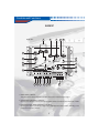
QUALITY, RLIABILITY, & PURE BLISS
MULTI-CHANNEL ELECTRONIC CROSSOVER
NETWORK WITH REMOTE CONTROL
AX303P
OPERATING INTSTRUCTIONS
PLEASE RETAIN MANUAL FOR FUTRE USE AND REFERENCE
Table of Contents
Table of Contents
INTRODUCTION
3
UNIT INTRODUCTION / INSTALLATION
4
CONTROLS AND FUNCTIONS
5-7
SIGNAL CONNECTIONS
8
WIRE CONFIGURATION
9
FEATURES
10
ADJUSTMENTS AND TROUBLESHOOTING
11
WARNING / DISCLAIMER
12
WARRANTY
13-14
2
The AX303P is an electronic crossover network. With this you can install various types of multi-channel
amplifier systems into your ehicle. By putting the AX303P in the center of your multi-channel amplifier car
stereo system, the unit will provide you with ultimate sound reproduction and distribution. The AX303P
crossover unit has built in line drivers which will help you adjust your level settings to match your source unit
and amplifiers.
Controls and Functions
AX303P
3
MAIN UNIT
5
4
22
6
AX303P
3 - WAY ELECTRONIC CROSSOVER WITH REMOTE CONTROL
PWR
2
Od8
BASS BOOST
40H Z
12d8
25H Z
250H
Z
BASS FREQ
400HZ
X-OVER FREQ
40HZ
80HZ
40HZ
80HZ
40HZ
LOW PASS
HIGH PASS
1
80HZ
HIGH PASS
7
X-OVER FREQ
MIN
MAX
NORMAL
INPUT LEVEL
REVERSE
OUT
9
BAND PASS
MID
FREQ
MULTI FILTER
IN / OUT
10
8
HIGH PASS
PHASE
IN
13
OUTPUT LEVEL
STEREO
14
MONO
MIN
MODE
11
MAX
SUB WOOFER
FRONT
MAX
MID - RANGE
MIN
MAX
HIGH PASS
OUTPUT
INPUT
REAR
MIN
IN / OUT
SUB
MID - RANGE
HIGH
L
L
REMOTE
R
R
SUB WOOFER
15 16 17
18 19 20
POWER
BATT
GND
FUSE
12
REM
21
1. INPUT LEVEL CONTROL
This gain control is used to adjust the sensitivity of the unit to match the radio's output.
2. SUBWOOFER FREQUENCY CONTROL
By turning the selector you can choose from an infinite number of crossover points from 40Hz - 400Hz.
3. BASS EQUALIZER / BASS FREQUENCY CONTROL
By turning the selector, you activate a single octave 12dB boost from 25Hz - 250Hz, depending on the
position of the frequency selector.
Controls and Functions
17. IN / OUT JACKS
You can use this connection if you have another pre-amp audio source or connect two or more
AX303P units together.
18. SUBWOOFER OUTPUT JACKS
Connect the RCA cable to the subwoofer channel of the amplifier input.
19. MID-RANGE OUTPUT PORT
Connect the RCA cable to the rear channel of the amplifier input.
20. HIGH-PASS OUTPUT JACKS
Connect the RCA cables to the front channel of the amplifier input.
21. POWER TERMINAL
Make connections using the supplied detachable plug. Connect the "B+" terminal to the battery positive
(+). Connect the "B-" terminal to chassis ground. Connect the REMOTE terminal to a 12V (switched) DC
source to allow the bass driver to be turned on/off by the head unit.
22. POWER LED
This blue LED light up when the unit is on.
REMOTE CONTROL UNIT
REMOTE CONTROLLER
Q.
LEVEL
MIN
2
MAX
20
AX303P
1
2
1. SUBWOOFER GAIN CONTROL
This control adjusts the subwoofer gain control.
2. Q SELECT
Allows independent, continuous change of the boost frequency bandwidth (Q-factor) for each band
from 20 (narrow bandwidth, steep slope), to 2 (wide bandwidth, gentle slopes).
Signal Connections
POWER CONNECTIONS:
Before connecting anything, be sure to disconnect the ground terminal from your battery to
prevent any damage to the audio components. Leave the ground wire disconnected until all components
are hooked up and the stereo is ready to play. Remove the power terminal from the AX303P before
fastening the wires into the correct slots as a precaution. Make sure you are looking at the terminal with
the set screws facing upwards while following the instructions.
B+:
The first slot from the left is the B+ or positive (+) 12V terminal. Connect this terminal to a
positive (+) 12V lead using the same source that powers your amplifiers. This should eliminate any
chance of picking up noise due to voltage differences. If you decide to run power wire for the crossover
directly to the battery, be sure to add an in-line fuse within a recommended 18 inches of the battery post.
This will protect both the system and the vehicle from possibly dangerous electric shock. Use a minimum
of 16 AWG stranded copper wire for this application and be sure to apply grommets whenever the power
wire is run through any metal wall.
GROUND:
The second slot from the left is the ground or B- terminal. To ground your AX303P, locate a solid
metal area close to the crossover that is a good source of ground (preferable the floor). Your best ground
will come from a grounding point attached directly to the frame of the vehicle. Investigate the area you
wish to use for electrical wires. Do not try to move vacuum, break or fuel lines. Using either a wire brush
or sandpaper to eliminate unwanted paint to supply a better contact when grounding. Use the same
gauge wire for ground as you did for the power wire. Terminate your ground wire using the correct size
ring terminal and attach it to bare metal using a #8 sheet metal screw. It is important for this connection to
be solid. To complete the job, spread silicon over the screw and bare metal to prevent rust and/or water
from entering.
REMOTE:
The third terminal from the left is the remote turn-on. This terminal must be connected to a
switched +12V source. Typically, remote turn-on leads are located by the source unit, which are used to
turn on and off all processors in correspondence with the source unit. If a radio does not have a remote
turn-on, then a power antenna wire may be used.
Wiring Configuration
AX303P
AX303P
3 - WAY ELECTRONIC CROSSOVER WITH REMOTE CONTROL
PWR
0dB
12dB
BASS BOOST
40H Z
25H Z
250H
Z
BASS FREQ
400HZ
X-OVER FREQ
LOW PASS
HIGH PASS
80HZ
40HZ
80HZ
40HZ
80HZ
40HZ
HIGH PASS
X-OVER FREQ
MIN
MAX
NORMAL
INPUT LEVEL
BAND PASS
REVERSE
IN
HIGH PASS
PHASE
OUT
MID
FREQ
MULTIPLIER
FUSE 3A
IN / OUT
STEREO
MONO
MIN
MODE
MAX
SUB WOOFER
FRONT
MIN
MAX
MID - RANGE
MIN
MAX
HIGH PASS
OUTPUT
INPUT
REAR
IN / OUT
SUB
MID - RANGE
+
HIGH
L
L
REMOTE
R
R
SUB WOOFER
POWER
BATT
GND
FUSE
REM
-
BATTERY
REMOTE CONTROLLER
Q.
LEVEL
MIN
MAX
2
20
AX202P
OPTIONAL REMOTE
LOW PASS LEVEL
AND Q LEVEL CONTROL
TWEETER
(MID)
WOOFER
TO INPUT
ADDITIONAL
AMPLIFIERS,
X-OVER OR
VIDEO SYSTEM
HEAD UNIT
SUB
WOOFER
REMOTE TURN-ON
US 6,656,000B2
DES. 423,503
9
Features
AX303P
Blue acrylic protective cover
2-way input source and 3-way output ports
Remote power on/off by remote turn-on
Remote control for Q-factor and subwoofer level control
DC to DC switching power supply.
Fully adjustable subwoofer mid, and high-pass output levels
Stereo / Mono mode switch
Variable bass boost frequency
Infinitely variable subwoofer, mid-range and high-pass crossover
Band-pass / high-pass switch on mid-range
Phase shift switch
In / Out switch
Built-in power protection fuse (3A)
Automatic ON/OFF DC power control with radio or tape player
Frequency multiplier (1x , 10x) on high-pass output
Specifications
Adjustable bass boost and bass frequency (25Hz - 250Hz)
Q-factor: 20-2 (variable)
Selectable crossover frequency
-Subwoofer (Low-pass): 40Hz - 400Hz
-Mid high-pass: 40Hz - 800 Hz
-Mid low-pass: 2kHz - 7kHz
-High-pass: 40Hz - 8kHz
Power supply: 10 - 16V DC negative ground
Input impedance: 10K ohm
S/N ratio: > 85dB
Slope rate: 18dB/octave
Max input level : 7V RMS
Channel Separation: 65dB
THD: Less then 0.05%
Dimensions: 9.3" (W) x 2.2" (H) x 5.9" (D)
11
4ECHNICAL!SSISTANCETECH AUDIOBAHNINCCOM
Warning / Disclaimer
WARNING
Investigate the layout of your automobile thoroughly before drilling or cutting any holes.
Take care when you work near the gas tanks, gas lines, hydraulic lines, and electrical wiring.
Attach the system securely to the automobile to prevent damage, particularly in the event
of an accident. Do not mount the system so that the wire connections are unprotected
or are subject to pinching or damage from nearby objects.
The +12V DC power wire must be fused at the battery positive terminal connection.
Before making or breaking power connections at the system power terminals,
disconnect the +12V wire at the battery end. Confirm your radio/head unit and/or other
equipment is turned off while connecting the input jacks and speaker terminals.
If you need to replace the power fuse, replace it only with a fuse identical to that
supplied with the system. Using a fuse of different type or rating may result in damage to
this system which is not covered by the warranty.
Disclaimer
Specifications are subject to change with out notice.
For the most updated Specifications call Audiobahn,
or your local Authorized Audiobahn Dealer,
or check the Audiobahn website.
www.audiobahninc.com
12
13
14