1
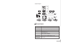
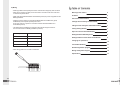
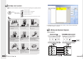
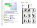
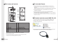
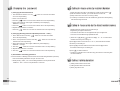
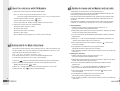
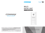
MULTI
ENTRY UNIT
Model No. DRC- MSC / MSB
• Thank you for purchasing our COMMAX product.
• Please carefully read this User’s Guide (in particular, precautions for safety)
before using the product and follow the instructions to use your productexactly.
• The company is not responsible for any safety accidents caused in abnormal operation of the product.
a513-11, Sangdaewon-dong, Jungwon-gu, Seongnam-si, Gyeonggi-do, Korea
Int’l Business Dept. : Tel.; +82-31-7393-540~550 Fax.; +82-31-745-2133
Web site : www.commax.com
Printed In Korea/ 2007.12
3)System diagram
CH2
13. Specification
Item
Wiring
Power voltage
Transmission Method
Screen dimension
Content(DRC-MSC/MSB)
To Build Distributor: 8-wire(talk 2, Data 2, Video 2, Power 2)
DC24~DC28V 5A ( powered by building distributor)
Duplex System
128x64 GRAPHIC LCD
Power requirement
Standby : 60mA
Maximum operation: 450mA(Max.)
Distance range
(to Build Distributor )
When power source is supplied from Building Distributor. Less than 20m
When power source is supplied separately. 20 ~100m
Distance range
(to Build Distributor )
5Lux ± 3 Lux
17
Table of Contents
2) Wiring
- Please pay attention to the polarity of the wires. Units will not work properly when mis-wired
- When using a UTP(CAT.5) cable, be sure to check the connection of the color of the wires
as shown in the picture above.
Warnings and caution
2
- Within 20m between Build Distributor and Multi Entry Panel, the power is supplied from the
Building Distributor.
Features
4
Part names and Functions
6
Calling In-house unite by resident Number
7
Calling In-house unite by the listed resident names
7
Calling / talking duration
7
Open the entrance with PIN Number
8
Setting the ID for Multi-Entry Panel
8
Setting In-House unit aas master and Sub Units
9
Changing the password
10
Connectable Products
11
Resident registration program
11
Wiring and System Diagram
15
Specification
17
- Greater than 20m to less than 100m between Build distributor and Multi entry panel,
the Multi Entry Panel requires separate power source
(In this case, there is no power line connection between the Build Distributor and
the Multi Entry Panel)
- The allotted ID of the Multi Entry Unit should match with the assigned number of
the connection terminal of Building Distributor (CCU-BS)
Multi Entry Panel
Build distributor
ID : 1
Terminal 1
ID : 2
Terminal 2
ID : 3
Terminal 3
ID : 4
Terminal 4
- When wiring, please use a tool like a screwdriver.
16
1
Warnings and caution
◎ Make sure to follow the instructions to prevent any danger or property losses.
It indicates prohibition.
Warning
It indicates prohibition of disassembly.
Death or serious
injury is expected.
It indicates prohibition of contact.
It indicates dos and don’ts.
It indicates that the plug should be pulled out from the socket.
Warning
Do not put the plug in the socket
simultaneously.
It may generate abnormal heat
or cause a fire.
Do not connect to other products
while in use.
It may cause breakdown.
Do not forcibly bend the cord or
put a heavy object on the product.
It may cause a fire.
17) With this data, you can make use of the “modify”, ”Add” functions in this program
and select “ SEND ” to complete.
13. Wiring and System Diagram
1) Wiring Diagram
2
Do not use water, thinner or a detergent used to wash oil products when
you wash the exterior.
Make sure to wash it by using a dry cloth to
prevent any breakdown or electric shock.
Do not install the product in a
humid place.
It may cause an electric shock or
a fire.
Do not forcibly pull out the
cord from the socket.
If the cord is damaged, it may
cause a fire or an electric shock.
Do not put the plug in the socket with a wet hand.
It may cause an electric shock.
Do not disassemble, repair or
modify the product.
It may cause a fire, an electric shock
or an injury due to malfunction of the
product.
Do not use AC circuit breaker.
It may cause an electric shock.
15
Warnings and caution
It indicates prohibition.
Caution
It indicates prohibition of disassembly.
An injury or property
losses are expected
It indicates prohibition of contact.
It indicates dos and don’ts.
It indicates that the plug should be pulled out from the socket.
Caution
12) “Completed sending” message is displayed as above, select (Y).
(When “LOBBY Not connected” message is displayed, please recheck the cable
connection, the Dip switches of the Building Distributor and “Select No.” & “Select Port”
in the program menu while shutting off the Building Distributor.
Then select “ Send ” again while the Building Distributor is on.
13) The file of the resident numbers and names stored for Building No.1 is automatically
saved in the format of AptNo1(e.g.: Building No. 2 —> AptNo 2.TXT) in the same
temporary folder.
14) Select “Exit” to quit this program.
15) Select “READ” brings the data from existing information of resident numbers and names
in the Building Distributor as shown in the image below.
16) “Name List” appears when selecting “READ” which is then saved into “Name Management”
by selecting “OK” (But for example, in case there is existing data stored in the temporary
folder in the format such as “AptNo1.txt” shown above, “Name list” shown below will not
take priority to be saved over the existing data, “AptNo1.txt”)
14
If the socket holes are larger
than normal, do not put the
plug.
It may cause an electric shock
or a fire.
Make sure that dust or foreign
substances are not gathered
on the product.
Make sure to prevent foreign
substances from entering the
product.
It may cause a breakdown.
Do not put a heavy object on
the product.
It may cause a breakdown.
Do not disassemble or give an
impact to the product.
Avoid direct rays of the sun or
heating devices at a time of
installation.
Install the product in a flat and
stable place.
Otherwise, it may not function
properly.
Pull the plug if the product is
not used for a long time.
If the product generates strange
sound, make sure to pull the
plug immediately and contact
Commax service center.
3
1. Features
8) Enter a resident number and name and then select “ OK ” to enter the next resident
number and name. (can be entered up to 200 resident numbers and names)
1) Wiring : 8 wires when including a power source ~
Simple installation - all wiring can be used with UTP cable(CAT.5)
2) Connect up to 4 Multi Entry Panels per building
3) Connect up to 4 residences per single Floor distributor (CCU-FS)
4) Connect Multi-Entry Panels with Building distributor (CCU-BS)
5) The power source is required for each Multi Entry Panel.(DC24V or DC-28V according
to the installation distance to Building Distributor.
6) All the in-house units (Color Video Phone, B/W Video Phone or Audio Phone) are
DC source type products and only the Master Unit is supplied with a power source from
the Floor Distributor.(CCU-FS) Additional in-house units need a separate power source,
except for the Audio type in house unit.(AP-5HM)
7) A door Camera unit does not serve as an individual door bell ,but a 2-wire door bell
type is supported for an individual door.
●Multi-Entry Units
With its slim, aluminum case and tempered glass camera lens, the Multi Entry Panel is
resistant to external impact.
It allows visitors to talk with residences list’ for names through the LCD display,
and easily register each residences’ name of each building or assigned area into the
9) Select “ Cancel ” to quit
10) In order to edit or delete, select the resident number and name among the existing
list of names as shown above , and Then you can modify through the selection of
“ Modify ”or “ Delete ”.
11) Select “ Send ” to complete and save this information into the Building Distributor.
Multi Entry Panel through the keypad or a personal computer.
Various selections are available among Video type with keypad ( DRC-MSC/MSB),
Video type by buttons(DRC-nSC/nSB) and Audio type (DR-nSB) according to clients’ needs.
Using a DRC-MSC (color) entry unit with a black & white videophone unit, as well as
using a DRC-MSB (black & white) entry unit with a color videophone unit, will cause
blurred images.
1) LCD size : 128x 64 (key pad type)
2) Connecting Door Bell type for an individual door.
3) Connectable to up to 4 units per building
4) Night automatic illumination - white LED illumination (built-in Camera)
5) Manual camera angle control
6) Full duplex
7) Power source DC 24V~ DC28V
4
13
3) Set the dip switches of Building Distributor to match its assigned ID.
4) Run “NAME TOOL_200.exe” file.
8) Screen display duration lasts for 30 seconds after receiving a call
9) Talking duration time last for 60 seconds.
10) Temperature limit : -10℃ ~ +40℃
11) Dimension(mm) : 140(W) x 341(H) x44(D)
12) Weight: 1570g
5) Select the Building ID in “ Select No ”. on the menu.
6) Select the port connecting with the computer in “ Select Port ”
7) Select “ Add ” to enter a resident number and name
▶Installation
Flush Mount Type
12
Surface Mount Type
5
11. Connectable Products
2. Part names and Functions
1) Building Distributor(CCU-BS) : one Building Distributor is connected to up to
4 Multi Entry Panels , Outside Distributor, Floor distributor and Audio type guard
station unit.
(Building Serial Numbers are allocated to each Buildings Distributor by its Dip Switch )
2) The Floor Distributor(CCU-FS) : one Floor Distributor can connect to up to
4 residences on each floor.
3) In-house unit: master unit can connect to up to 2 Sub-units per residence.
4) Audio type unit: this unit can be used for external unit to communicate to residences
such as Guard station through one-way communication.
5) A Program to register residences: resident name is entered in the Building Distributor
by a personal computer.
12. Resident registration program (NAME TOOL_200)
This program updates through the company web site (WWW.COMMAX.COM)
1) Download “ NAME TOOL_200.zip” through COMMAX homepage and expand
the zip files to a temporary folder.
No.
Contents
No.
Contents
1
C-MIC
10
Power status and Light night lamp
2
Lamp for CCD Camera
11
Dial button
3
CDS Sensor
12
Key
4
CCD Camera
13
Cancel button
5
LCD Display
14
Camera angle control
6
Down button
15
Terminal for door release
7
Right and Left button
16
Volume control for receiving call
8
Call button
17
Connection terminal to CCU-BS
9
Speaker
2) Connect the side, D-sub connector of download cable to the serial port of the PC and
Connect other side , 3P connector to RS232 Port of Building Distributor
This is the Entrance unit that is connectable to up to 4 units with a
Building Distributor(CCU-BS).
It can be connected with the Floor distributor unit(CCU-FS) which connects
4 residence through the Building Distributor (CCU-BS)
6
11
10. Changing the password
3. Calling In-house unite by resident Number
1) Changing Resident Password
1. Hold “Residence Number” and “Key
button for 2 seconds and release
when LCD stops blinking.
2. Enter “Current password“
3. Hold “Key
1) Press the buttons according to the residence number and then Press “
”
2) After the residence answers, you can talk with the in-house unit.
3) “Beep” will sound in the cause of a wrong number,
4) “Line Busy” is indicated on the LCD of Multi Entry panel when already talking
with others through the Panel.
button for 2 seconds and release when LCD stops blinking.
4. Enter “New Password“ with 4 digits on Multi Entry Panel displaying
“NEW PW : “message.
5. Hold “Key
button for 2 seconds and release when LCD stops blinking.
4. Calling In-house unite by the listed resident names.
6. Repeat “New password“ to confirm it.
7. Hold “Key
“ button for 2 seconds and release when LCD stops blinking.
2) Changing Building Password (default password : “4321”)
1. Enter “9900“ and then hold “Key
“ button for 2 seconds and release
1) Press one of [▼], [◀ ▶], [
when LCD stops blinking.
2. Enter “current password“ and then hold “Key
“ button for 2 seconds and
release when LCD stops blinking.
3. Enter “New Password“ with 4 digits on Muti-Entry Panel displaying
“NEW PW : “message.
4. Hold “Key
“ button for 2 seconds and release when LCD stops blinking.
5. Repeat “New password“ to confirm it.
6. Hold “Key
- Register residents’ names into the CCU-BS through
“Programming for register residence list ”
- A maximum of 200 names can be registered with up to 18 digits each.
- The name can be strolled through alphabetical order.
”button for 2 seconds and release when LCD stops blinking.
] buttons to display “A” ~ “Z” on LCD to select
resident name that you are looking for..
2)Press [▼] to select one of them from “A” to “Z ”, which includes the resident
name that you are looking for.
3)Press [◀ ▶] to scroll to resident name section and Press [▼] to select
the resident name that you are looking for.
4)Press [
] to call the residence.
* “Line Busy” is indicated on the LCD of the entry panel when it is connecting with
3) Initialization of building password
the same residence.
* All the information of Building Passwords is stored in the Building Distributor.(CCU-BS)
1. Shut off the Building Distributor and open the unit’s case.
2. While pressing “ SW2 “, turn on the Building Distributor and the password will
5. Calling / talking duration
initialize to “ 4321 “ and the Lamp will blink for 3 seconds.
1) Calling duration lasts for 30 seconds.
2) Talking duration lasts for 60 seconds.
3) Press [ X ] button to end
10
7
6. Open the entrance with PIN Number
1. Opening the common entrance with Household Number
Note : The doors do not open by default password “ 1234 ”
Only after changing default Password to new one, can you use this function.
1) Press resident number” and “KEY
button
2) Press PIN number and the “KEY
button
The door opens with the “OPEN” message display on the LCD screen.
2. Opening the common entrance with PIN Number
1)Enter the number sequence, “9900”.
8. Setting in-house unit as Master and sub units
• Setup begins from the multi-entry unit connected to channel 1.
•In one household, there should only be one established MASTER multi-entry unit.
The remaining units should be set as SLAVE units.
•From the household number registration mode, pressing the “Door release” button
sets the unit as MASTER, and pressing the “Extension Call” button sets the unit
as SLAVE.
•After completing registration of the household number, set the multi-entry unit's ID
number to “1”. (If a multi-entry unit's ID is set to “0”, it is not in normal operation)
1. Setting Master
2)Press the “KEY” button.
1) Set the multi-entry unit's ID number connected to channel 1, to “ 0 ”.
(From the household number registration mode)
3)Enter the PIN number of a building.
2) While picking up the handset of an in-house unit, press the “Extension call” button
and the “door release” button at the same time.
4)Press the “KEY” button.
5)If the “OPEN” message appears, the common entrance will open.
3) You can communicate with the Multi Entry Panel while the resident’s number is
displayed on it.
4) When the “✽✽✽-> M” message is displayed on the Multi Entry Panel when you
press the “Door release” button on an in-house unit.
5) Then, register the ID of the shown residence, and press “
7. Setting the ID for Multi-Entry Panel
First set the ID number sequence for the multi-entry unit to “0”. After each multi-entry unit
has been installed, the user must program the building distributor's channels to correspond with each multi-entry unit's ID number, 1 to 4.
(CH1 → ID:1, CH2 → ID:2, CH3 → ID:3, CH4 → ID:1)
If a multi-entry unit's ID is set to “0”, then it is in household registration mode.
(If a multi-entry unit's ID is set to “0”, it is not in normal operation)
1) Hold “Key
“ button for 2 seconds and then release when the LCD stops blinking.
2) When “Password” message appears on the LCD, enter the password set for the
Building and press the “Key
” button.
3) When “ ID : “ message appear on the LCD, enter the number from 1 to 4 in order.
4) Then press the “ Key
“ button to complete ID setting.
” button to hear
a sound of completion.
6) The registration is complete when you hang up the handset.
(Repeat this process to register other room numbers.)
7) After completing registration of all household numbers, be sure to set a multi-entry
unit's ID to “1”.
2. Setting the Sub-Unit
1) Set the multi-entry unit's ID connected to channel 1, to “0”.
(From the household number registration mode)
2) While picking up the handset of an in-house unit, press the “Extension call” button
and the “door release” button at the same time.
3) You can communicate with Multi Entry Panel while the resident’s number
displayed on it.
4) In that status, “✽✽✽-> S “message is displayed on the Multi Entry Panel
when you press the “Extension call” button on the in-house unit.
5) Then, register the ID of the said residence, and press “
sound of completion.
” button to hear a
6) The registration is complete when you hang up the handset.
(Repeat this process to register other room numbers.)
8
7) After completing registration of all household numbers, be sure to set a multi-entry
unit's ID to “1”.
9