1
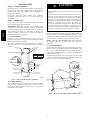
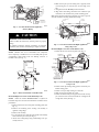
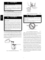
b. If fan coil is against wall, secure fan coil to wall stud
using 1/8--in (3 mm) thick right--angle brackets. Attach
brackets to fan coil using no. 10 self--tapping screws
and to wall stud using 5/16--in. lag screws. (See Fig. 8.)
DRAIN PAN
SUPPORT BRACKET
4” (102mm) MAX
SECURE FAN COIL TO STRUCTURE
UNIT AWAY FROM WALL
PIPE STRAP
(TYPICAL BOTH SIDES)
OR
UNIT AGAINST WALL
.125" (3mm)
MOUNTING BRACKET
(TYPICAL BOTH SIDES)
A07571
FX4D
Fig. 7 -- Drain Pan Support Bracket
6. Convert air--seal assembly for horizontal right.
a. Remove air--seal assembly from coil by removing 4
screws. (See Fig. 6.)
b. Remove air splitter (B) from coil seal assembly by removing 3 screws. (See Fig. 3--factory shipped inset.)
c. Remove filter plate (A) and install air splitter (B) in
place of filter plate.
d. Install filter plate (A) as shown in horizontal right application.
e. Remove condensate troughs (C) and install on opposite
tube sheets.
f. Install hose onto plastic spout.
7. Install horizontal pan on right side of coil assembly.
8. Slide coil assembly into casing. Be sure coil bracket on each
corner of vertical pan engages coil support rails.
9. Reinstall 2 snap--in clips to correctly position and secure
coil assembly in unit. Be sure clip with large offsets is used
on right side of unit to secure horizontal pan.
10. Remove two oval fitting caps from the left side of the coil
door and fitting panel.
11. Remove insulation knockouts on right side of coil access
panel.
12. Remove 2 oval coil access panel plugs and reinstall into
holes on left side of coil access panel and fitting panel.
13. Install condensate pan fitting caps (from item 10) in the
right side of the coil door making sure that the cap snaps
and seats cleanly on the back side of the coil door. Make
sure no insulation interferes with seating of the cap.
14. Reinstall access fitting panels, aligning holes with tubing
connections and condensate pan connections. Be sure to reinstall metal clip between fitting panel and vertical condensate pan.
Make sure liquid and suction tube grommets are in place to prevent
air leaks and cabinet sweating.
D. Manufactured and Mobile Home Housing Applications
1. Fan coil unit must be secured to the structure using field-supplied hardware.
2. Allow a minimum of 24--in (610 mm) clearance from access
panels.
3. Recommended method of securing for typical applications:
a. If fan coil is away from wall, attach pipe strap to top of
fan coil using no. 10 self--tapping screws. Angle strap
down and away from back of fan coil, remove all slack,
and fasten to wall stud of structure using 5/16--in. lag
screws. Typical both sides of fan coil.
DOWN FLOW
BASE KIT (KFACB)
SECURE UNIT TO FLOOR
ANGLE BRACKET OR PIPE STRAP
4” (102mm) MAX
A07567
Fig. 8 -- A--Coil
Step 3 — Air Ducts
Connect supply--air duct over the outside of 3/4--in (19 mm)
flanges provided on supply--air opening. Secure duct to flange,
using proper fasteners for type of duct used, and seal duct--to--unit
joint. If return--air flanges are required, install factory--authorized
accessory kit.
Use flexible connectors between ductwork and unit to prevent
transmission of vibration. When electric heater is installed, use
heat--resistant material for flexible connector between ductwork
and unit at discharge connection. Ductwork passing through
unconditioned space must be insulated and covered with vapor
barrier.
Units equipped with 20--30kW electric heaters require a 1--in (25
mm) clearance to combustible materials for the first 36--in (914
mm) of supply duct.
Ductwork Acoustical Treatment
Metal duct systems that do not have a 90_ elbow and 10--ft (3m) of
main duct to first branch takeoff may require internal acoustical
insulation lining. As an alternative, fibrous ductwork may be used
if constructed and installed in accordance with the latest edition of
SMACNA construction standard on fibrous glass ducts. Both
acoustical lining and fibrous ductwork shall comply with National
Fire Protection Association as tested by UL Standard 181 for Class
1 air ducts.
Step 4 — Electrical Connections
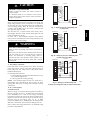
All products from the factory protect the low voltage circuit with a
5 amp automotive type fuse inline on the wire harness. Speed
selections are made at the fan motor by selecting taps 1, 2 or 3 with
the blue wire (see section E). The motor is pre--programmed with
the time delay circuit on some of the speed taps ( see section E for
clarification).
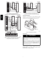
When a factory--approved accessory control package has been
installed, check all factory wiring per unit wiring diagram and
inspect factory wiring connections to be sure none were loosened
in transit or installation. If a different control package is required,
see unit rating plate.
4