1
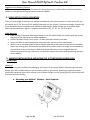
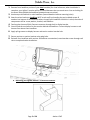
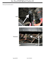
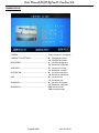
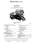
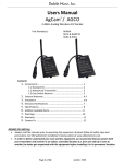
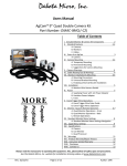
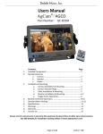
Dakota Micro, Inc. Users Manual AGCO AgCam® Combine Kits AGCO Part Numbers: BQC9K-C2T ........................... 2 Camera, Quad Monitor Field Install Transverse Combine Kit BQC9K-C4T ........................... 4 Camera, Quad Monitor Field Install Transverse Combine Kit BQC9K-C2A ........................... 2 Camera, Quad Monitor Field Install Axial Combine Kit BQC9K-C4A ........................... 4 Camera, Quad Monitor Field Install Axial Combine Kit BUSBK-C2 ............................. C2100 - 2 Camera Field Install Kit Transverse & Axial Kit Contents: 1. 2. 3. 4. 5. 6. 7. 8. 9. 10. 11. 12. 13. 14. Page Included Components & Warnings ...............................................2 Standard Features a. Camera ........................................................................3 b. Monitor........................................................................3 c. Cables ..........................................................................3 Camera Installation & Mounting ...................................................4 Cable Installation & Mounting ......................................................4-5 Monitor Installation & Mounting ..................................................5-7 a. Axial Combines ............................................................5-6 b. Transverse Combines ..................................................6 Installing the C2100 Video Adaptor ..............................................7 Installing the Under Cab Harness ................................................7-8 Monitor & Remote Operation .......................................................8-10 Monitor Menu Settings .................................................................11-12 Quad Menu Settings ......................................................................13-16 Specifications .................................................................................17 Warranty........................................................................................18 Warnings........................................................................................19 Dealer Information ........................................................................20 Always read the manuals prior to operating this equipment. Please follow all safety signs and precautions. Page 1 of 20 Author: CMZ User Manual AGCO AgCam® Combine Kit 1. INCLUDED COMPONENTS All Field Install Kits Include: Qty 1 – Four (4) camera input, under cab harness (AGCO PN: BCOMB-4C). 9” Quad Monitor Kit Include: Transverse - BQC9K-C2T and BQC9K-C4T kits include: Qty 1 – 9” Quad Monitor Qty 2 – Monitor Bracket Wing Bolts Qty 1 – Transverse Combine Monitor Bracket Qty 1 – Monitor Remote Axial - BQC9K-C2A and BQC9K-C4A kits include: Qty 1 – 9” quad monitor Qty 2 – Monitor Bracket Wing Bolts Qty 1 – Axial Combine Monitor Bracket Qty 1 – Monitor Remote C2100 Kits Include: BUSBKC2 kits include: Qty 1 – USB Video Input Adaptor for C2100 Monitor Camera Kits Include: BQC9K-C2T, BQC9K-C2A and BUSBK-C2 kits include the following cameras & cables: Qty 2 - AGCO AgCam® PAL Cameras (AGCO PN: AC-RC). Qty 1 - 20’ Power/Video Cable (AGCO PN: AC-EC20). Qty 1 - 40’ Power/Video Cable (AGCO PN: AC-EC40). BQC9K-C4T and BQC9K-C4A kits include the following cameras & cables: Qty 4 - AGCO AgCam® PAL Cameras (AGCO PN: AC-RC). Qty 2 - 20’ Power/Video Cable (AGCO PN: AC-EC20). Qty 2 - 40’ Power/Video Cable (AGCO PN: AC-EC40). Camera Warnings NEVER RELY ON YOUR AGCAM® AS A SAFETY FEATURE. It is up to you to keep your road travel and other operations safe. Your AgCam® will provide you with information only based on what it sees. Operation of machinery safety guidelines still apply. The AgCam® is equipped with an array of infrared light emitters which are invisible to the human eye. This feature will aid in low light conditions but has limitations. The effective range of the night vision feature is 1 to 45+ feet and will produce a monochrome image only. Do not attempt to drive machinery using this feature. 2. STANDARD FEATURES a. Camera Waterproof, shockproof, suitable for nearly any use. Minimum focal distance of 5”. Page 2 of 20 Rev: 03/10/14 Dakota Micro, Inc. Built-in, high quality CCD camera with high performance infrared (IR) illuminator modules. IR has effective range of 45’+ in complete darkness. In-line conditioner and surge suppressor prevents over/under powering of unit, preventing damage. Built-in CDS light-source sensor can automatically turn on/off the IR’s by detecting the light intensity of the environment. Our exclusive Photogray camera body lens darkens in bright conditions and becomes completely transparent under low light conditions. This lens is also transparent of infrared light, allowing the LED’s to penetrate even when its darkened. Standard lens features 92° field of view (3.6mm). Optional lenses available include: 6mm, 12mm & 16mm. Removable/Replaceable camera tail. b. Quad Monitors Features the latest in LCD technology. Adjust brightness, contrast, saturation, hue and sharpness for each camera, adjustable for both the monitor and quad settings. Credit card style remote control included Full quad display at real time refresh rate (60fps). Supports both NTSC and PAL video formats. Camera title settings allow you to uniquely name each camera. Individually mirror each camera. On screen display includes date & time. View 1, 2 or 4 cameras at the same time. c. Cables Silicone jacket enables high flexibility in all temperatures. AGCO combine camera kits include durable extension cables in 20’ and 40’ standard lengths and feature sturdy, watertight connectors. Custom video cables lengths available: 10’, 20’, 30’, 40’, 50’, 60’and 80'. 3. CAMERA INSTALLATION & MOUNTING Temporary Mounting For temporary mounting, it is recommended that you use the supplied 65# pull magnet. If using magnetic mount, fasten camera cable with a zip tie or other style fastener. This will act as a “safety wire” in the event your camera is knocked loose for some reason. When selecting a location, make sure that the equipment surface is clean of all foreign material and as flat as possible to ensure that the magnetic camera base will have good contact and not vibrate off. Permanent Mounting: For permanent mounting, it is recommended that you remove the magnet and attach to any solid surface with two (2) screws. After camera is securely mounted, attach the camera pigtail (AGCO PN: AC-CT) into the back of the camera. You can now plug your camera tail into the power/video input into AgCam® extension power/video cable. Make sure they are securely attached and locked (¼ turn will lock the cables together). Page 3 of 20 Author: CMZ User Manual AGCO AgCam® Combine Kit Suggestions for Mounting Camera: When determining the location for the camera it is always best to use a solid surface to minimize vibration. Ladders are not good mounting choices due to lack of stability. 4. CABLE INSTALLATION & MOUNTING There is 1 (one) length of cable for each camera included with your camera system: In a two camera kit, you will receive one (1) 20’ and one (1) 40’ power/video cable. (or two of each if you have selected a 4 camera kit). If you would like to purchase different or additional cable lengths, please contact your local AGCO dealer where you purchased your AgCam®. Lengths are available in 10’, 20’, 30’, 40’, 50’,60’ and 80'. Cable Warnings Cable routing is important. Where you choose to run the cables should not interfere with the normal operation of the machine or any safety equipment. ALWAYS be aware of any “pinch points” or other potential hazards to the cable. Secure all cables to vehicle/equipment using cable clips, zip ties or other style fastener. While in use on combine hopper or other combine operations, take care to remember that combines have many moving parts. Use extreme care when routing cables, and it is strongly recommended that you use bolts to secure the camera. While it would be sufficient to use the magnetic base for monitoring purposes during road travel, it is advised to secure the camera with bolts during operation of the combine. 5. MONITOR INSTALLATION & MOUNTING FOR KITS INCLUDING AGCAM QUAD MONITORS: Mounting: Remove your monitor carefully from packaging, and inspect all mounting hardware. Mounting location and bracket style will vary depending on type of combine (Axial or Transverse). Mounting locations have been specifically selected to ensure your monitor is out of direct sunlight, this will prolong the life of the unit as well as ensure optimum visibility. a. Mounting your AgCam® Monitor – Axial Combine: Page 4 of 20 Rev: 03/10/14 Dakota Micro, Inc. 1. Remove front headliner portion of your Axial combine (for visual reference, when installation is 2. 3. 4. 5. 6. complete, your AgCam® monitor will be mounted between the two round vents. You are looking for the access holes behind the headliner between these two points). Knockout pre-drilled hole in main headliner (located between bracket mounting holes). Attach monitor bracket to headliner (NOT to cab roof) by threading the two included screws & washers into bottom of the monitor bracket, through main headliner. With this in mind, the order of components will be: screw, washer, bracket, and headliner. Feed monitor harness/Quick Connect connector through hole in display bracket. You will find the connection for the monitor behind the headliner. Connect display harness to cab harness from above front headliner. Apply split grommet to display harness and seat in monitor bracket hole. 7. Secure monitor to monitor bracket using wing bolts. 8. Reinstall front headliner with monitor and bracket now attached, screw bracket screws through roof cab to complete bracket installation. b. Mounting your AgCam monitor –Transverse Combine: Page 5 of 20 Author: CMZ User Manual AGCO AgCam® Combine Kit 1. 2. 3. 4. 5. 6. 7. Locate the bracket mounting hole on the front side of the front, right hand cab post. Secure bracket to post temporarily using standard bolt. Position bracket on post so that display mounting tabs are level. Using a pencil, mark the location on the post for the 2nd screw. Remove the bolt that was temporarily installed in step 2 and set the bracket aside. Drill a 7/32”diameter hole in the post at the location marked in step 4. Place bracket on post and install using the standard bolt on the front (left) side and a thread rolling screw on the rear (right) side. 5. INSTALLING YOUR C2100 VIDEO ADPATOR For BUSBK-C2 kits only. 1. Plugs into Quick Connect port located behind headliner (see section 5 for location). 2. Plugs into USB port on rear of C2100 monitor. IMPORTANT: C2100 Monitors can ONLY display 2 cameras. Page 6 of 20 Rev: 03/10/14 Dakota Micro, Inc. 6. INSTALLING YOUR UNDER CAB HARNESS (Transverse & Axial): Your under cab video harness looks like this: 1. Plugs into port on underside of combine 2. AgCam® video input ports (max 2 for C2100, max 4 for AgCam® Quad monitor) On both Axial and Transverse combines, your under cab harness video connector will be located under the center, front section of the cab, as indicated below: Page 7 of 20 Author: CMZ User Manual AGCO AgCam® Combine Kit Close up of connection points Axial: Transverse: Page 8 of 20 Rev: 03/10/14 Dakota Micro, Inc. 7. Monitor & Remote Operation Turn the monitor on only after it has been securely mounted, supplied with power, and the cameras are connected. Front of 9” Quad Monitor: 1 Output Jack Headphone Jack 2-4 FOR USE ONLY WITH Quad Processor 2 3 Full Screen Duplex Screen When connected to DM Quad, will show cameras 1/2/3/4 each time pressed. When connected to DM Quad will show cameras 1 /4 and cameras 2 /3 each time pressed. 4 Quad Screen When connected to DM Quad will display all four (4) cameras connected. 5 - Key To decrease parameter. 6 + Key To increase parameter. 7 MENU To switch menu selection, press multiple times. To go to next icon, use +. 8 AV Key Switches between AV1, AV2, AV3, & AV4. 9 POWER Turns monitor ON/OFF . 11-12 ports located on sides and bottom of monitor 10 USB Port Input for optional cable when using a computer connected to the VGA port. (duplicates image from input device) 11 Quad Plug USB female connector for Quad processor. 12 VGA Input Input for VGA from computer or other console .(duplicates image from input device) Page 9 of 20 Author: CMZ User Manual AGCO AgCam® Combine Kit Back of 9” Quad Monitor: and and ENTER MENU Move up and down through individual menu options Move left and right through individual menu options Allows users to select a chosen Quad option Button displays quad menu options on your monitor Remote: POWER ON/OFF Mute Enable/Disable sound Flip image Left/Right Flip image Up/Down Navigation Arrows MENU Enters the menu Also acts as “enter” button in menu settings Adjusts screen display modes Reset your selection Enables timer that will turn off monitor Superimpose a grid on screen Aspect Ratio adjustment normal/wide Chooses the highlighted selection in MENU Page 10 of 20 Rev: 03/10/14 Dakota Micro, Inc. Getting Started: IMPORTANT: There are two different menu settings sections within the 9MQ monitor. Monitor menu settings, and Quad menu settings. A. Standard Monitor Menu Settings 1. Power on monitor by pushing “POWER” button on the face of monitor or remote. 8. Monitor Menu Settings Press the MENU key on the monitor (#7 pictured on pg. 9) or the remote. Use the – and + keys on the monitor or the left and right arrow keys on the remote to move through the icons at the top of the screen. 1. Use the MENU key on the monitor (up and down arrows on remote) to select an item under each section. Selected menu items turn red. 2. Use – or + on the monitor (left and right arrows on remote) to change the value of the highlighted item. 3. To exit: a. Press the – or + key on the monitor (left or right arrow on remote) multiple times till the menu until goes away. b. Allow monitor to time out (approximately 5 seconds). PICTURE BRIGHT: Adjusts the brightness of the image CONTRAST: Adjusts the contrast of the image COLOR: Adjusts the color of the image TINT: Adjust tint of image (appears only when camera is plugged in) RESET: Returns settings to default VOLUME VOLUME: Adjusts the volume level Page 11 of 20 Author: CMZ User Manual AGCO AgCam® Combine Kit OPTION CAMERA 1: AV1 event trigger delay time CAMERA 2: AV2 event trigger delay time CAMERA 3: AV3 event trigger delay time CAMERA 4: AV4 event trigger delay time ROTATE: Invert image on screen SYSTEM LANG: Select your language (English default) SOURCE: Has no function GUIDE LINES: Super imposes a grid on your monitor screen (select ON or OFF) PRESET SLEEP: Enables sleep timer delay setting (in minutes) AV1: Enable (ON) or Disable (OFF) AV1 AV2: Has no function AV3: Has no function AV4: Has no function VGA: Enable (ON) or Disable (OFF) VGA input Page 12 of 20 Rev: 03/10/14 Dakota Micro, Inc. 9. QUAD MENU SETTINGS - Located on the top, back of monitor 1. 2. 3. 4. 5. 6. 7. Press and hold the MENU button (Refer to pg. 10) for 3 seconds Use arrow buttons (Refer to pg. 10) to select desired menu to adjust. Use ENTER button (Refer to pg. 10) to select desired option on any menu screen. Use MENU button to exit out of any menu option. move up and down through individual menu options. . Press and hold MENU button for 3 seconds to exit menu setup. Page 13 of 20 Author: CMZ User Manual AGCO AgCam® Combine Kit SYSTEM SETUP: DATE ........................................Set your current date. MONTH:DAY: YEAR TIME .........................................Set your current time. HOUR:MINUTE:SECOND SYSTEM FORMAT .....................Video system. NTSC/PAL selectable SYSTEM ID NUMBER ................Select unique ID # for Quad KEY LOCK..................................When set to ON position, only individual camera views available When set to OFF position, all functions available CAMERA PRIORITY ...................Function not available on this model VCR OUT ..................................Function not available on this model POWER ON OUTPUT ................Selects the type of display image shown on power on FACTORY RESET.......................Restores unit to factory preset options Page 14 of 20 Rev: 03/10/14 Dakota Micro, Inc. DISPLAY SETUP: DISPLAY ON SCREEN ....................... Press ENTER to “Check” what information is displayed on screen SCREEN POSITION ........................... X: moves screen to right, moves screen to left Y: moves screen up, moves screen down BORDER COLOR .............................. Press ENTER to select displayed border color TIME SETUP: AUTO SEQUENCE TIME ................... Auto Sequence Time allows for automatic rotation of the images, full screen, on the monitor. You can adjust the delay time for each camera from 1 to 99 seconds. NOTE: You cannot set any image to 00 or the display will get stuck on this image indefinitely. 00 is reserved for future use to disable one or more cameras from the rotation. Press the key on the key board, the screen will show quad view, and then press again the screen will rotate between cameras 1-4. HOLD TIME SETUP .......................... Function not available on this model. Page 15 of 20 Author: CMZ User Manual AGCO AgCam® Combine Kit CAMERA SETUP: CAMERA ............................................................... Select cameras 1-4 to adjust CAMERA TITLE SETTINGS ..................................... Changes parameter Changes parameter BRIGHTNESS ........................................................ Increases brightness Decreases brightness CONTRAST ........................................................... Increases contrast Decreases contrast SATURATION ........................................................ Increases saturation Decreases saturation HUE ...................................................................... Increases hue Decreases hue SHARPNESS .......................................................... Increases sharpness Decreases sharpness MIRRORING ......................................................... OFF=non mirrored ON=mirrored image Page 16 of 20 Rev: 03/10/14 Dakota Micro, Inc. 10. WARNINGS 1) To avoid electrical shock and maintain optimal functionality, do not open the enclosures. High voltage may be present and there are no user serviceable parts inside. All warranties will be void should any enclosures be tampered with in any way. 2) Do not use any harsh chemical solvents, cleaning agents or corrosive detergent to clean away dirt on the surface of the screen or lens. 3) Our photo-chromic camera lenses have been made impact-resistant and have been drop-ball tested according to Sec. 3.84,21 CRF BUT ARE NOT UNBREAKABLE. Because they have been hardened chemically, they show no stress pattern. Inspect your lenses frequently. Chipped or scratched surfaces will reduce protection. Such lenses should be replaced only by the manufacturer. 4) This camera uses a special coated optic lens with photo chromatic properties; if the lens needs to be replaced we require that it be returned to the factory. 5) Power to cameras is not interrupted by turning off monitor; 12v power source must be terminated when not in use to avoid battery drain. To avoid this problem be sure when hard wiring a unit, use a fused circuit. 6) Do not use your Dakota Micro camera system for anything other than legal surveillance and observation uses. Dakota Micro, Inc. is not liable for any illegal or nefarious usage. Page 17 of 20 Author: CMZ User Manual AGCO AgCam® Combine Kit 11. ADDITIONAL AVAILABLE ITEMS (NOT INCLUDED IN AC-9MQ KIT) Description Ranch Hand Wireless Transmitter Only: Includes 3dBi antenna, wall plug power, cigarette lighter power, RCA adaptor Part Number Picture AC-RHTX Ship Weight: 1.47 lbs Ranch Hand Wireless Receiver Only: Includes 3dBi antenna, wall plug power, cigarette lighter power, RCA adaptor AC-RHRX Ship Weight: 1.47 lbs 8DBI Wireless Panel Antenna: Flat mount directional antenna w/20’ cable AC-WA8P Ship Weight: 1.55 lbs 8DBI Wireless Antenna: Omnidirectional antenna w/20’ cable AC-WA8 Antenna Length: 17 inches Ship Weight: 1.05 lbs AgCam 3.6mm Camera w/ pigtail, no extension cables (92 degree field of view) AC-RC Ship Weight: 1.28 lbs 30’ Shielded Power/Video Cable Length: 30 feet : Ship Weight: 0.92 lb AC-EC30 40’ Shielded Power/Video Cable Length: 40 feet : Ship Weight: 1.19 lbs AC-EC40 Contact your local dealer for more information or to place an order. Page 18 of 20 Rev: 03/10/14 Dakota Micro, Inc. 12. CONSUMER LIMITED WARRANTY LIMITED WARRANTY Subject to the disclaimer, limitations and other directions stated hereafter, Dakota Micro, Inc. warrants that the Product will be free from defects in material and workmanship for periods as stated hereafter from the date of original purchase. THIS WARRANTY IS EXPRESSLY MADE IN LIEU OF ANY AND ALL OTHER WARRANTIES, EXPRESS OR IMPLIED, INCLUDING THE IMPLIED WARRANTIES OF MERCHANTABILITY OR FITNESS. THE EXCLUSIVE REMEDY OF THE BUYER IS LIMITED TO REPAIR OR REPLACEMENT OF THE PRODUCT. EXCEPT AS STATED IN THIS WARRANTY, DAKOTA MICRO SHALL NOT BE LIABLE FOR ANY LOSS, INCONVENIENCE, OR DAMAGE, INCLUDING DIRECT, SPECIAL, INCIDENTAL, OR CONSEQUENTIAL DAMAGES, RESULTING FROM THE USE OR INABILITY TO USE THE PRODUCT, WHETHER RESULTING FROM BREACH OF WARRANTY, NEGLIGENCE, STRICT LIABILITY OF ANY OTHER LEGAL THEORY. Any oral statements or representations made by anyone which are contrary to or at variance with the terms stated in this LIMITED WARRANTY are void. Dakota Micro will, at its option, either repair the defect or replace the defective Product or part thereof with a new or remanufactured equivalent at no charge to the purchaser for parts or labor for the period of three (3) years for AgCam®/EnduraCam® cameras, two (2) years for AgCam®/EnduraCam® monitors, quads and Wireless Ranch Hands, Eighteen Months (18) for all Overview Cameras & Monitors and one (1) year for Mini DVR, cables and all other accessories. The Dakota Micro limited warranty periods outlined above apply throughout the United States and Canada only. A one (1) year maximum limited warranty for all Products applies to all other geographic locations unless otherwise stated in writing by Dakota Micro. This limited warranty does not apply to any issues connected with appearance that have no relation to the performance of the Product nor to any Product the exterior of which has been damaged or defaced, which has been subjected to improper voltage or other misuse, abnormal service or handling, or which has been altered or modified in design or construction. In order to enforce the rights under this limited warranty, the purchaser should follow the steps set forth in the complete Dakota Micro “Warranty & Repair Policy” listed at www.dakotamicro.com , and provide proof of purchase to Dakota Micro. Neither the sales personnel of Dakota Micro nor any dealer or any other person is authorized to make any warranties other than those described herein, or to extend the duration of any warranties beyond the time periods described herein. The warranties described herein shall be the sole and exclusive warranties and remedies provided by Dakota Micro. Correction of defects, in the manner and for the period of time described herein, shall constitute complete fulfillment of all liabilities and responsibilities of Dakota Micro to the purchaser with respect to the Product, and shall constitute full satisfaction of all claims. In no event shall Dakota Micro be liable or in any way responsible for any damages or defects in the Product which were caused by repairs or attempted repairs performed by anyone other than Dakota Micro. Some states do not allow the limitation or exclusion of incidental or consequential damages, so said limitation may not apply to you. Any action at law, suit in equity, or other judicial proceeding for the enforcement of any right provided for herein or otherwise, or with respect to any claim that a purchaser may have against Dakota Micro shall be instituted only in the Courts of the State of North Dakota, either in the state district court located in Wahpeton, North Dakota or in Federal District Court location in Fargo, North Dakota. Without regard to conflicts of law principles, the laws of the state of North Dakota shall govern the interpretation and enforcement of the terms of this Limited Warranty and all aspects of the relationship between Dakota Micro and the purchaser. This warranty gives you specific legal rights and you may also have other rights, which may vary from state to state. Page 19 of 20 Author: CMZ User Manual AGCO AgCam® Combine Kit 13. CONTACT US Dakota Micro Inc. products, specifications, pricing and programs are subject to change without prior notice. Dakota Micro Inc. reserves the right to make design changes at any time without obligation to retroactively install them on previously sold units. Dakota Micro, Inc. 1 866 462-4226 www.dakotamicro.com 8659 148th Ave. SE Cayuga, ND 58013 Page 20 of 20 Rev: 03/10/14