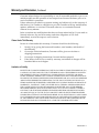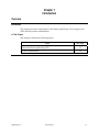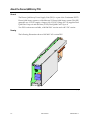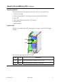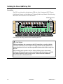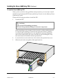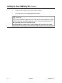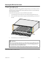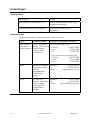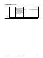
1
Dense QAM Array
Power Supply Unit
Please Read This Entire Guide
Important
Please read this entire guide before you install or operate this product. Give
particular attention to all safety statements.
Dense QAM Array
Power Supply Unit
Notices
Trademark Acknowledgments
· Continuum DVP, “Bringing the Interactive Experience Home”, and SciCare are
trademarks of Scientific-Atlanta, Inc.
· Scientific-Atlanta, the Scientific-Atlanta logo, Continuum, and Mercury are
registered trademarks of Scientific-Atlanta, Inc.
· All other trademarks shown are trademarks of their respective owners.
Publication Disclaimer
Scientific-Atlanta, Inc., assumes no responsibility for errors or omissions that may
appear in this publication. Scientific-Atlanta reserves the right to change this
publication at any time without notice. This document is not to be construed as
conferring by implication, estoppel, or otherwise any license or right under any
copyright or patent, whether or not the use of any information in this document
employs an invention claimed in any existing or later issued patent.
Copyright
©2002 Scientific-Atlanta, Inc. All rights reserved. Printed in Belgium.
Information in this publication is subject to change without notice. No part of this
publication may be reproduced or transmitted in any form, by photocopy, microfilm,
xerography, or any other means, or incorporated into any information retrieval
system, electronic or mechanical, for any purpose, without the express permission of
Scientific-Atlanta, Inc.
Contents
Safety Precautions .....................................................................................................................................iv
Guidelines for Users.................................................................................................................................... v
Guidelines for Service Personnel.............................................................................................................. vi
Warranty and Disclaimer............................................................................................................................ ix
Preface
About This Guide............................................................................................................ xi
Chapter 1
Introduction
Overview........................................................................................................................1-1
About the Dense QAM Array PSU.............................................................................1-2
Product Identification...................................................................................................1-4
Chapter 2
Installation
Overview........................................................................................................................2-1
Installing the Dense QAM Array PSU .......................................................................2-2
Removing the PSU from the chassis...........................................................................2-5
Chapter 3
Customer Information
Overview........................................................................................................................3-1
Product Support ............................................................................................................3-2
Returning Products.......................................................................................................3-4
Appendix A
Technical Specifications
Specifications ................................................................................................................A-1
Glossary ...................................................................................................................................... Glossary-1
6984278 Rev A
iii
Safety Precautions
Read and Retain Instructions
All electrically powered units can be dangerous. We have taken great care to ensure
safety during the design and production of our units. Incorrect installation, handling
or component replacement can, however, impair safety.
Safety guidelines in this manual and labels or instructions on the unit are provided
to warn users and service personnel about residual risk.
Carefully read all safety and operating instructions before operating this product,
and retain them for future reference.
Warning and Caution Icons
WARNING:
Avoid personal injury and product damage! Do not proceed beyond any icon
until you fully understand the indicated conditions.
The following icons alert you to important information about the safe operation of
this product:
You will find this icon in the literature that accompanies this product. This
icon indicates important operating or maintenance instructions.
You may find this icon affixed to this product. This icon indicates a live
terminal; the arrowhead points to the terminal device.
You may find this icon affixed to this product. This icon indicates a
protective earth terminal.
You may find this icon affixed to this product. This icon indicates excessive
or dangerous heat.
Service Personnel, Users and Operators
The terms defined below are used frequently in this manual. The definitions given
are based on definitions in the safety standards in question, but partially simplified
to help the explanation.
The term service personnel applies to trained and qualified individuals who are
allowed to install, replace or service electrical equipment. The service personnel are
expected to use their experience and technical skills to avoid possible injury to
themselves and others due to hazards that exist in service and restricted access areas.
The term user or operator applies to all other persons than service personnel.
iv
6984278 Rev A
Guidelines for Users
Precautions
The following precautions are applicable to users:
To prevent electrical shock or fire hazard:
· Do not remove covers.
· No operator serviceable parts inside.
· Refer servicing to qualified personnel.
· Do not expose this unit to rain or moisture.
· Disconnect the main- and backup-power before changing fuses.
For continued protection against risk of fire:
· Replace only with the same type and rating of fuse.
6984278 Rev A
v
Guidelines for Service Personnel
General
The specific warnings and precautions in the sections below are applicable to service
personnel.
Requirements for the Installation Site
You should select the installation site carefully. Observe the following rules:
· Protective Earth
The protective earth lead of the building installation should comply with the
national and local requirements.
· Environmental Condition
Keep in mind that electronic equipment requires a dry and clean environment
with proper ventilation and cooling facilities. High-humidity conditions can cause
corrosion and degradation of electrical components. At all times the installation
site should be dry, clean and ventilated. Temperature extremes can cause a variety
of problems such as product failure, hardware damage, etc. Ensure that the
product is operated in an environment that meets the requirements as stated in the
unit’s technical specifications.
Electrical Shock Hazard
Electrical shock can cause personal injury or even death. At any time you must avoid
direct contact with dangerous voltages. The protective earth connection is essential
to safe operation and must be verified before connecting the power supply. You
should know the following safety warnings and guidelines:
· Dangerous Voltages
- Product installation or replacement must be performed by service personnel
only.
- Only service personnel are allowed to remove chassis covers and access any of
the components inside the chassis.
- After service, assemble the unit and ensure it is safe to use before you put it back
in operation.
· Earthing
- Do not violate the earth protection by using an extension cable, power cable or
autotransformer without a protective earth conductor.
- Take care to maintain the protective earthing of the unit during service or repair
and to re-establish it before you put it back in operation.
Continued on next page
vi
6984278 Rev A
Guidelines for Service Personnel, Continued
Fire Hazard
Incorrect use or installation of electrical equipment can cause a risk of fire. Be aware
of the following:
· Ventilation
Slots and openings in the product housing are provided for ventilation. Do not
block these openings and slots as insufficient airflow can be unsafe and cause fire.
· Critical Component Replacement
For continued protection against risk of fire; replace critical components only with
components of the same type and rating.
· Fuse Replacement
Replace fuses only with fuses of the same type and rating.
Precautions
Be aware of the following general precautions and guidelines:
· Wristwatch and Jewelry
For your personal safety and to avoid damage of the unit during service and
repair, do not wear electrically conducting objects such as wristwatch or jewelry.
· Lightning
Do not work on the product, or connect or disconnect cables during periods of
lightning.
· Labels
Do not remove any warning labels. Replace damaged or illegible warning labels
with new ones.
ESD
Electrostatic discharge (ESD) results from the static electricity build up on the human
body and other objects. This static discharge can degrade components and cause
failures.
Observe the following rules to reduce ESD effects:
· Do not attempt to open a unit without proper precautions against electrostatic
discharge such as:
- Use a wrist or ankle strap.
- Use an anti-static tablemat when working inside a product.
· Keep components in their anti-static packaging until you install them.
- Avoid touching electronic components when installing e.g. a module.
Continued on next page
6984278 Rev A
vii
Guidelines for Service Personnel, Continued
EMC
To meet the EMC requirements of Directives 89/336/EEC and 93/68/EEC you must
use correctly shielded cables of good quality for all external connections, except the
power, when installing the unit.
Observe the following rules:
· Make sure that all multi-connector cables have conductive connector housings
with shielded clamps. Exceptions from this general rule will be clearly stated in the
connector description for the excepted connector in question.
· Make sure that the coaxial cables are of the double-braided type.
© 2002 Scientific-Atlanta, Inc. All rights reserved.
viii
6984278 Rev A
Warranty and Disclaimer
Statement
Scientific-Atlanta (S-A) warrants good title to any hardware furnished by it. S-A
warrants that during the Warranty Period as defined below services will be
performed in a good and workmanlike manner. S-A also warrants that during the
Warranty Period, each item S-A delivers (other than separately licensed software
and services) (an “Item”) will be free from material defects in workmanship and
materials and under ordinary use, conform in all material respects to its published
specifications current at the time the Item was shipped, downloaded, otherwise
delivered to Customer. During the Warranty Period, S-A will use reasonable
commercial efforts to correct errors detected in licensed software after receiving
notification of such errors from Customer.
Items may include refurbished goods, subassemblies, or components, which S-A
warrants as provided in this section.
Warranty Period
The Warranty Period begins on the date the Item is delivered and extends for 12
months for hardware and 90 days for software, parts, and services. S-A will repair or
replace, at its option, any product that fails to satisfy this Warranty and that is
returned to S-A by Customer at Customer’s expense during the Warranty Period,
unless the failure was the result of shipping; improper installation, maintenance or
use; abnormal conditions of operation; attempted modification or repair by
Customer; or an act of God. S-A will re-perform any services that do not conform to
this Warranty provided S-A has received notice of non-conformance within the
Warranty Period.
Disclaimer
THIS WARRANTY IS IN LIEU OF ALL OTHER WARRANTIES, EXPRESS, IMPLIED, OR
STATUTORY, INCLUDING ANY WARRANTY OF MERCHANTABILITY, FITNESS FOR A
PARTICULAR PURPOSE, OR NONINFRINGEMENT. S-A DOES NOT WARRANT THAT
THE FUNCTIONS CONTAINED IN ANY LICENSED SOFTWARE WILL MEET THE
CUSTOMER’S REQUIREMENTS OR THAT THE OPERATION OF THE LICENSED SOFTWARE WILL BE UNINTERRUPTED OR ERROR-FREE. ANY THIRD-PARTY SOFTWARE
SUPPLIED WITH OR INCORPORATED IN ANY ITEM IS PROVIDED “AS IS,” WITHOUT
WARRANTIES OF ANY KIND. IF A THIRD PARTY SUPPLIES ANY ADDITIONAL
WARRANTIES, SUCH WARRANTIES WILL BE OFFERED DIRECTLY BY SUCH THIRD
PARTY TO CUSTOMER. CUSTOMER'S SOLE REMEDY FOR ANY BREACH OF WARRANTY IS THE REPAIR OR REPLACEMENT, AT S-A’S OPTION, OF THE FAILED ITEM.
S-A SPECIFICALLY DISCLAIMS ANY AND ALL WARRANTIES, EXPRESS OR IMPLIED,
TO CUSTOMERS, RESELLERS, DISTRIBUTORS, OR END USERS OF CUSTOMER.
Customer’s Responsibility
Customer must pay packing, crating, and transportation costs to and from the
factory.
At Customer’s request, S-A will make reasonable efforts to provide warranty service
at Customer’s premises, provided Customer pays S-A’s then current rates for field
services and the associated travel and living expenses.
Continued on next page
6984278 Rev A
ix
Warranty and Disclaimer, Continued
Customer acknowledges its responsibility to use all reasonable methods to prove out
and thoroughly test the operation of and output from Licensed Software prior to its
use in Customer's operations.
Unless otherwise provided in a separate writing, and subject only to the warranty of
this Section, S-A is under no obligation to provide Customer with any modifications,
updates, additions, or revisions to licensed software, or to maintain licensed
software in any manner.
In the event that any modifications that have not been authorized by S-A are made to
licensed software, any and all warranty and other obligations of S-A shall
immediately cease with respect to such software.
Claims Under This Warranty
In case of a claim under this warranty, Customer should do the following:
1.
Notify S-A by giving the Item model number, serial number, and details of
the difficulty.
2.
On receipt of this information, Customer will be given service data or
shipping instructions.
3.
On receipt of shipping instructions, forward the Item prepaid.
4.
If the Item or fault is not covered by warranty, an estimate of charges will be
furnished before work begins.
Limitation of Liability
EXCEPT FOR CLAIMS FOR PERSONAL INJURY CAUSED BY ITEMS FURNISHED BY S-A,
S-A SHALL NOT BE LIABLE TO THE CUSTOMER OR ANY OTHER PERSON OR ENTITY
FOR INDIRECT, SPECIAL, INCIDENTAL, CONSEQUENTIAL, PUNITIVE, OR EXEMPLARY DAMAGES ARISING OUT OF OR IN CONNECTION WITH THE TRANSACTION
IN WHICH THE ITEMS OR SERVICES WERE FURNISHED OR ANY ACTS OR OMISSIONS
ASSOCIATED THEREWITH OR RELATING TO THE SALE, LICENSE, OR USE OF ANY
ITEMS OR SERVICES FURNISHED, WHETHER SUCH CLAIM IS BASED ON BREACH OF
WARRANTY, CONTRACT, TORT, OR OTHER LEGAL THEORY AND REGARDLESS OF
THE CAUSES OF SUCH LOSS OR DAMAGES OR WHETHER ANY OTHER REMEDY
PROVIDED HEREIN FAILS. IN NO EVENT SHALL S-A’S TOTAL LIABILITY UNDER A
CONTRACT OR PURCHASE ORDER FOR HARDWARE ITEMS OR SERVICES EXCEED
AN AMOUNT EQUAL TO THE TOTAL AMOUNT PAID FOR SUCH ITEMS PROVIDED
UNDER THE CONTRACT OR PURCHASE ORDER. IN NO EVENT SHALL S-A BE LIABLE
TO CUSTOMER FOR ANY DAMAGES RELATED TO LICENSED SOFTWARE IN EXCESS
OF THE LESSER OF TEN THOUSAND UNITED STATES DOLLARS (US$10,000) OR THE
LICENSE FEE PAID BY CUSTOMER TO S-A FOR THE LICENSED SOFTWARE.
x
6984278 Rev A
Preface
About This Guide
Introduction
This guide provides the needed technical information to install the Dense QAM
Array Power Supply Unit (PSU).
Audience
The audience of this user manual includes users (operators) and service personnel who
are responsible for the installation, operation and service of the Dense QAM Array
PSU. For further information about the definition of operator and service personnel,
see safety guidelines and precautions earlier in this manual.
Scope
This guide provides the following topics.
· The PSU function description
· The installation procedures
· The technical specifications
Related Publications
Refer to the following Scientific-Atlanta publications for more information.
· Continuum DVP Dense QAM Array System Guide, part number 698428, or
Mercury Dense QAM Array System Guide, part number 4000997
· Continuum DVP Dense QAM Array Processor Module Installation and Operation
Guide, part number 6984280, or
Mercury Dense QAM Array Processor Module Installation and Operation Guide, part
number 4000996
· Dense QAM Array Dual QAM Card Installation and Operation Guide, Part number
6984279
© 2002 Scientific-Atlanta, Inc. All rights reserved.
6984278 Rev A
Preface
xi
Chapter 1
Introduction
Overview
Introduction
This chapter provides a description of the Dense QAM Array Power Supply Unit
(PSU) and the product identification.
In This Chapter
This chapter contains the following topics.
Topic
6984278 Rev A
See Page
About the Dense QAM Array PSU
1-2
Product Identification
1-4
Introduction
1-1
About the Dense QAM Array PSU
General
The Dense QAM Array Power Supply Unit (PSU) is a part of the Continuum DVP™
Dense QAM Array system or of the Mercury™ Dense QAM Array system. This PSU
generates two 12 V DC supply voltages. One 12 V DC voltage (12 VA) supplies Dual
QAM Card 1 up to 4 and the other (12 VB) Dual QAM Card 5 up to 8.
Two PSU versions are available, a 100-240 VAC version and a -48 V DC version.
Drawing
The following illustration shows a 100-240 V AC version PSU.
Continued on next page
1-2
Introduction
6984278 Rev A
About the Dense QAM Array PSU, Continued
Features and Benefits
The standard features and benefits for the 100 - 240 V AC version PSU are:
· Universal AC input
· Inrush current limited, overvoltage protection and thermal shutdown
· Quasi-PFC
· 2 non-isolated fully protected 12 V DC outputs
· High efficiency
· High reliability
Indication LEDs
The PSU is provided with 2 LEDs that indicate the status of the 12 V DC supply
voltages.
12 VA
12 VB
The following table describes the PSU LEDs.
6984278 Rev A
LED
Color
Description
12 VA
Green
This led illuminates when the 12 VA is OK.
12 VB
Green
This led illuminates when the 12 VB is OK.
Introduction
1-3
Product Identification
General
Products can be identified by means of the ID label attached to the product.
The following information is available on the label(s).
· Company address
· Model number
· Serial number
· Part number
· Nominal supply voltage
· Maximum current
Under some circumstances you might need this information. For example when a
unit is failing, the serial number is necessary for returning your unit.
Label
The following is an example of the identification label:
BarcoNet n.v.
EC SERIAL NR: 5768817
Luipaardstraat 12 - 8500 Kortrijk
MODEL: Power Supply Unit PART NR: V9524805
I MAX : 1,8 A
FUSE: T 4A H 250 V
U NOM: 100 - 240 VAC
The label is located on the rear side of the PCB.
Note: This identification label is an example and does not contain exactly the same
information as the label attached to your unit.
© 2002 Scientific-Atlanta, Inc. All rights reserved.
1-4
Introduction
6984278 Rev A
Chapter 2
Installation
Overview
Introduction
This chapter describes the installation of a Dense QAM Array Power Supply Module
(PSU) in the chassis. It is assumed that all safety precautions and guidelines have
been followed prior to performing the installation procedures in this chapter.
It is recommended that the entire installation procedure in this chapter is read prior
to performing the Dense QAM Array PSU installation.
In This Chapter
This chapter contains the following topics.
Topic
6984278 Rev A
See Page
Installing the Dense QAM Array PSU
2-2
Removing the PSU from the chassis
2-5
Installation
2-1
Installing the Dense QAM Array PSU
Introduction
The PSU is positioned in the right most PCB slot of the Continuum DVP™ Dense
QAM Array Chassis or of the Mercury™ Dense QAM Array Chassis. The following
illustration shows the PSU slot in the chassis.
PSU Module position
1
2
3
4
5
6
7
8
Observe the following cautions when installing the PSU.
CAUTIONS:
During installation, the connector on the PSU must line up evenly with the
connector inside the card slot. When inserting the unit into the module slot,
ensure that the unit is level and the top and the bottom sides slide evenly into
the slot.
PSU contains static-sensitive devices. Always follow proper electrostatic
discharge (ESD) handling procedures (wristband with ground strap and ESD
mat) when installing cards in your chassis. Follow Electronic Industries
Association (EIA) standard EIA-625.
Continued on next page
2-2
Installation
6984278 Rev A
Installing the Dense QAM Array PSU, Continued
To Install the Dense QAM Array PSU
When you have read the safety guidelines and precautions, you are ready to install
the PSU in the Continuum DVP Dense QAM Array Chassis or in the Mercury Dense
QAM Array Chassis.
Perform the following procedure to install the PSU.
1.
Unpack the PSU.
CAUTION:
Follow proper ESD handling procedures.
ESD may cause permanent damage to electronic components.
When unpacking a unit, examine it, the accessories, and the packing material
for obvious signs of damage. Check the unit against the delivery/packing
note. Retain the packing material, as it is required for warranty shipments
and for later inspection by the carrier. Should any item be damaged, notify
the carrier and your Scientific-Atlanta representative.
2.
Loosen the three screws at the front of the chassis and open the front cover.
3.
Slide the card in the card guides of the right-hand slot.
1
2
3
4
5
6
7
8
Continued on next page
6984278 Rev A
Installation
2-3
Installing the Dense QAM Array PSU, Continued
4.
Push the unit carefully into the back-plane connector.
5.
Close the front cover and tighten the three screws.
CAUTION:
The six fans mounted on the front cover of the chassis assure sufficient cooling
of the system only when the hinged front cover is closed. During operation of
the system the front cover should be closed.
Ascertain that the cooling works properly during the operation of the system.
2-4
Installation
6984278 Rev A
Removing the PSU from the chassis
To Remove a Dense QAM Array PSU
When you have read the safety guidelines and precautions, you are ready to remove
the PSU from the Continuum DVP Dense QAM Array Chassis or from the Mercury
Dense QAM Array Chassis.
Perform the following steps to remove the PSU from the chassis:
1.
Loosen the three screws at the front of the chassis and open the front cover.
2.
Pull out the PSU from the chassis using the handle (bended lip) on the front of
the unit.
0
1
2
3
4
5
6
7
8
Handle
3.
Close the front cover and tighten the three screws.
CAUTION:
The six fans mounted on the front cover of the chassis assure sufficient cooling
of the system only when the hinged front cover is closed. During operation of
the system the front cover should be closed.
Ascertain that the cooling works properly during the operation of the system.
© 2002 Scientific-Atlanta, Inc. All rights reserved.
6984278 Rev A
Installation
2-5
Chapter 3
Customer Information
Overview
Introduction
This chapter contains information on obtaining product support and returning
damaged products.
In This Chapter
This chapter contains the following topics.
Topic
6984278 Rev A
See Page
Customer Information
3-1
Returning Products
3-4
Customer Information
3-1
Product Support
Obtaining Support
IF you have…
THEN…
general questions about this product
Contact your distributor or sales agent
for product information.
technical questions about this product
Contact the customer services
department.
Assistance Centers
Use the following table to find the assistance center in your area.
Region
Assistance Centers
Telephone, Fax Numbers and E-mail
North America SciCare™ Broadband
· For Technical Support, call:
South America
Services – a division of
Toll-free
1-800-722-2009
Central America Scientific-Atlanta
Local
770-236-5400
Atlanta, Georgia
Fax
770-236-5748
United States
· For Customer Service questions, call:
Toll-free
Local
Fax
1-800-722-2009
770-236-6900
770-236-5477
Europe
BarcoNet nv-Belgium
- a Scientific-Atlanta
company
Luipaardstraat 12
B-8500 Kortrijk
Belgium
Telephone
Fax
E-mail
32-(0)56 445 197
32-(0)56 445 053
[email protected]
Europe
Telephone
BarcoNet A/SDenmark- a Scientific- Fax
Atlanta company
E-mail
Tobaksvejen 23A
DK-2860 Søborg
Denmark
45 39 17 00 00
45 39 17 00 10
[email protected]
Continued on next page
3-2
Customer Information
6984278 Rev A
Product Support, Continued
Asia
6984278 Rev A
Telephone
BarcoNet Sdn. Bhd–
Malaysia- a Scientific- Fax
Atlanta company
E-mail
Lot L1-E-3B Enterprise
4—Technology Park
Malaysia—Lebuhraya
Puchong-Sg. Besi
Bukit Jalil
57000 Kuala Lumpur
Malaysia
Customer Information
60 3 8996 1988
60 3 8996 1988
[email protected]
3-3
Returning Products
Introduction
The procedure to return a product depends on the region where you are located. If
you are located in North, South, or Central America, you should follow the
procedure Returning the Product to Scientific-Atlanta - North, South, or Central
America. If you are located in a region outside America, you should follow the
procedure Returning the Product to BarcoNet - Europe or Asia.
Returning the Product to Scientific-Atlanta - North, South, or Central America
Introduction
Returning a product to Scientific-Atlanta for repair includes the following steps:
· Obtaining a return material authorization (RMA) number
· Packing and shipping the product
The following sections describe each of these procedures in detail.
Obtaining an RMA Number
You must have an RMA number to return products.
RMA numbers are valid for 60 days. If you already have a number, but it is older
than 60 days, you must contact a Scientific-Atlanta SciCare Broadband Services
representative to revalidate the number. You can return the product after the RMA
number is revalidated.
Follow these steps to obtain an RMA number.
1.
Contact a SciCare Broadband Services representative to request a new RMA
number or revalidate an existing one.
You can either call a representative or fill out and fax an RMA Request form.
2.
IF you want to…
THEN…
fax in an RMA Request Form
proceed to step 2.
call to request an RMA number
proceed to step 4.
Fill out the RMA Request Form, and fax it to SciCare Broadband Services at
1-770-236-5477.
Result: A customer service representative writes an RMA number on the
form and faxes the form back to you.
3.
Proceed to Packing and Shipping the Product.
Continued on next page
3-4
Customer Information
6984278 Rev A
Returning Products, Continued
4.
Telephone SciCare Broadband Services to request an RMA number.
Are you located within the United States?
· If yes, call 1-800-722-2009.
· If no, call 1-770-236-5300
5.
Provide the following information to the customer service representative:
· Product model number and/or part number
· Number of products to return
· Symptom(s) you are experiencing with the product
· Your company name, contact, telephone number, fax number, and repair
disposition authority
· Any service contract details
· Purchase order number, if available
Result: The representative issues the RMA number.
Notes: If you cannot provide a purchase order number:
· A proforma invoice listing all costs incurred will be sent to you at the
completion of product repair.
· SciCare must receive a purchase order number within 15 days after you
receive the proforma invoice.
· Products can accrue costs through intentional damage or misuse, or if no
problem is found. If your company requires a purchase order number to
make payment for repairs, products incurring costs will not be dispatched
to you without a valid purchase order number.
6.
Proceed to Packing and Shipping the Product.
Continued on next page
6984278 Rev A
Customer Information
3-5
Returning Products, Continued
Packing and Shipping the Product
Follow these steps to pack the product and ship it to Scientific-Atlanta.
1.
Are the product’s original container and packing material available?
· If yes, pack the product in the container using the packing material.
· If no, pack the product in a sturdy, corrugated box, and cushion it with
packing material.
Important: You are responsible for delivering the returned product to
Scientific-Atlanta safely and undamaged. Shipments damaged due to
improper packaging may be refused and returned to you at your expense.
2.
Write the following information on the outside of the container:
· Your name
· Complete address
· Telephone number
· RMA number
Note: Absence of the RMA number may delay processing of your product for
repair. Make sure to include the number in all correspondence to ScientificAtlanta.
3.
Are you shipping the product from a location within the United States?
· If yes, proceed to step 4.
· If no, do the following:
- Consign international shipments to Scientific-Atlanta, Inc., with the
notified party on the Airway Bill stated as “Expediters International for
Customs Clearance”.
- Proceed to step 4.
4.
Ship the product prepaid and insured to the following address.
Scientific-Atlanta, Inc.
RMA Number ____________
Factory Services
4245 International Boulevard
Norcross, GA 30093
USA
Important: Be sure to prepay all shipments, as Scientific-Atlanta does not
accept freight collect.
Continued on next page
3-6
Customer Information
6984278 Rev A
Returning Products, Continued
Returning the Product to BarcoNet - Europe or Asia
Use the following procedure to return a unit for repair.
1.
Contact the nearest customer services center to obtain a Return Authorization
Number (RAN).
The customer services representative will ask for the unit’s serial number,
which is required to generate the RAN.
2.
Ask the customer services representative to which customer center the unit
should be returned.
It may be another than the one you contacted.
3.
Package the unit carefully and include any information you can about the
problems you are currently experiencing with the unit.
4.
Attach the address label to the shipping carton. Be sure to include the RAN.
5.
Ship the unit.
© 2002 Scientific-Atlanta, Inc. All rights reserved.
6984278 Rev A
Customer Information
3-7
Appendix
Appendix A—Technical Specifications
Appendix A
Technical Specifications
Specifications
Introduction
The following tables list the technical specifications of the Dense QAM Array Power
Supply Unit
Note: Technical specifications are subject to change without prior notice.
Environment Specifications
Item
Specification
Ambient temperature range:
·
Within specs
10 to 40°C /50 to 104°F
·
Operation
0 to 50°C /32 to 122°F
·
Storage
-20 to 70°C /-4 to 158°F
Physical Specifications
Item
Specification
Dimension
·
In mm
55 W x 100 H x 385 D
·
In inch
2.2 W x 3.9 H x 15.2 D
Weight
1.3 kg / 2.86 lbs
Continued on next page
6984278 Rev A
Technical Specifications
A-1
Specifications, Continued
Electrical Specifications
Item
Specification
Input voltage range
100 - 120 / 200 - 240 V AC
Output
Two non-isolated outputs 12 V DC
Output voltage: 12.25 ± 0.25 V (± 2%)
No adjustments necessary.
Maximum Spec. SMPS (with forced aircooling)
6.25 A on each output (150 W output
power)
Maximum Load in application
5.2 A (120 W output power)
Nominal load in application
4.2 A (96 W output power)
Minimal load
0.25 A (to start up the SMPS)
Output current limit for each 12 V
output
6.7 A (short circuit proof)
No derating over entire temperature
range
Nominal load from 0°C (32°F) up to
45°C (113°F)
Efficiency
83%
Switching frequency
± 66 kHz (Forward converter)
No load input power
Max. 5 W
Inrush current limitation with NTC
resistance
110 V: max. 50 A @ peak line
220 V: max. 100 A @ peak line
Fuse
4 A T (internal fuse size 5 x 20 mm)
© 2002 Scientific-Atlanta, Inc. All rights reserved.
A-2
Technical Specifications
6984278 Rev A
Glossary
Term, Acronym,
Abbreviation
Meaning
DVP
Digital Video Platform
EIA
Electronic Industries Association
EMC
ElectroMagnetic Compatibility
ESD
Electrostatic Discharge
LED
Light Emitting Diode
PCB
Printed Circuit Board
PSU
Power Supply Unit
QAM
Quadrature Amplitude Modulation
RAN
Return Authorization Number
RMA
Return Material Authorization
SMPS
Switched Mode Power Supply
© 2002 Scientific-Atlanta, Inc. All rights reserved.
6984278 Rev A
Glossary-1
Want
MORE?
www.scientificatlanta.com
United States
Now
TALK
to someone
Comment
about this
DOCUMENT
Scientific Atlanta, Inc., 5030 Sugarloaf Parkway, Box 465447, Lawrenceville, GA 30042; Tel: 770.903.5000
Europe
Scientific Atlanta Europe GmbH, Westerbachstrasse 28, 61476 Kronberg, Germany; Tel: 49.6173.928.000
BarcoNet n.v. - Belgium, Luipaardstraat 12, B-8500 Kortrijk, Belgium; Tel: +32 (0)56 445 197
Asia-Pacific
Scientific Atlanta (Singapore) Pte. Ltd., 1 Claymore Drive, #08-11 Orchard Towers, Singapore 229594; Tel: 65.733.4314
Latin America
Scientific Atlanta Argentina S.A., Carlos Pelligrini 1149, Piso 11°, Capital Federal C1009ABW, Buenos Aires, Argentina;
Tel: 54.11.4325.2800
If you have comments about your experience with this documentation, please visit the Scientific-Atlanta web site and complete the
user documentation satisfaction survey at the following address:
http://www.scientificatlanta.com/my2cents/doc_survey.htm
Your completed survey will be forwarded to the documentation manager directly responsible for publishing this document.
© 2002 Scientific-Atlanta, Inc. All rights reserved.
This document includes various trademarks of Scientific-Atlanta, Inc.
Please see the Notices section of this document for a list of the Scientific-Atlanta trademarks used in this document.
All other trademarks shown are trademarks of their respective owners.
Product and service availability subject to change without notice.
Part Number 6984278 Rev A
Printed in Belgium July 2002