1
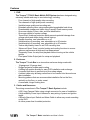
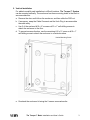
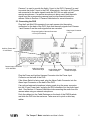
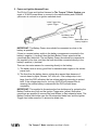
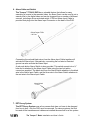
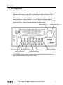
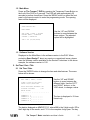
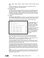
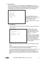
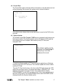
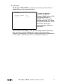
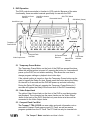
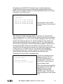
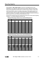
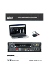
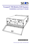
the
TM
BASIC
by
TR4-10 Basic Mobile DVR System
Installation and User’s Guide
Please Read All Instructions Carefully
Before Beginning Installation
*700-0022*
Document Part Number: 700-0022 R004
© 2006 Seon Design™ Inc. All Rights Reserved.
This page intentionally left blank.
The Trooper™ Basic Installation and User’s Guide
ii
Introduction
Thank you for purchasing The Trooper™ TR4-10 Basic Mobile Digital Video
Recording (DVR) System. We are sure you will find this system to be a very
high quality, reliable solution to your video monitoring requirements.
Please install this equipment as shown in this manual. Improper installation may
cause irreparable damage to the components - please follow all local, state and
federal safety regulations during installation.
The Trooper™ Basic Mobile DVR System specifications are subject to change
without notice. Please contact Seon Design™ if you have any questions or
concerns about The Trooper™ System specifications.
Seon Design™ Inc.
Unit 111, 3B Burbidge Street
Coquitlam, BC
Canada V3K 7B2
Tel: (604) 941-0880
Fax: (604) 941-0870
Toll Free: 877-630-7366
E-mail: [email protected]
© 2006 Seon Design™ Inc.
All rights reserved.
The Trooper™ Basic Installation and User’s Guide
iii
Table of Contents
FEATURES .............................................................................................................................. 1
1. DVR .............................................................................................................................. 1
2. Enclosure....................................................................................................................... 1
3. Cables and Harnesses.................................................................................................... 1
INSTALLATION ..................................................................................................................... 2
1. Horizontal Installation .................................................................................................. 2
2. Vertical Installation....................................................................................................... 3
3. Installing the DVR ........................................................................................................ 4
3.1 Installing with the SCT-LD Enclosure ............................................................... 4
3.2 Description of DVR Connectors......................................................................... 4
3.3 Connecting the DVR........................................................................................... 5
4. Camera Cable................................................................................................................ 6
5. Power and Ignition Harness/Fuses................................................................................ 7
6. Alarm Cable and Switch ............................................................................................... 8
7. EZT Decoy System ....................................................................................................... 8
OPERATION............................................................................................................................ 9
1. DVR Programming ....................................................................................................... 9
1.1 Front Panel Controls ........................................................................................... 9
1.2 Main Menu........................................................................................................ 10
1.3 Software Version .............................................................................................. 10
2. Set Time / Date / Title................................................................................................. 10
2.1 Set Time / Date ................................................................................................. 10
2.2 Auto Daylight Saving ....................................................................................... 11
2.3 Display Voltage ................................................................................................ 11
2.4 Main Title.......................................................................................................... 11
2.5 Camera Titles .................................................................................................... 11
3. Record Mode / Schedule............................................................................................. 12
3.1 Record Speed .................................................................................................... 12
3.2 Picture Quality .................................................................................................. 12
3.3 Repeat Record................................................................................................... 13
3.4 Record Audio .................................................................................................... 13
3.5 Delay-On Time ................................................................................................. 13
3.6 Delay-Off Time................................................................................................. 14
3.7 Timers ............................................................................................................... 14
3.8 Alarm Recording............................................................................................... 15
4. System/Defaults .......................................................................................................... 16
4.1 Alarm Buzzer .................................................................................................... 16
4.2 Format Disk ...................................................................................................... 17
4.3 System Update .................................................................................................. 17
4.4 Load Defaults.................................................................................................... 18
4.5 Format CF Card ................................................................................................ 18
4.6 Password ........................................................................................................... 19
5. DVR Operation ........................................................................................................... 20
5.1 Temporary Power Button.................................................................................. 20
5.2 Video Output Jack............................................................................................. 20
5.3 Compact Flash Card Slot .................................................................................. 20
5.4 Hard-Drive Lock............................................................................................... 21
The Trooper™ Basic Installation and User’s Guide
iv
5.5 Hard-Drive Power Indicator ............................................................................. 21
5.6 Hard-Drive Access Indicator ............................................................................ 21
5.7 Removable Hard-Drive..................................................................................... 21
5.8 IR Remote Control Receiver............................................................................. 21
5.9 Alarm Input Indicator ....................................................................................... 21
5.10 DVR Power Indicator........................................................................................ 21
5.11 Channel Buttons ................................................................................................ 22
5.12 MODE Button ................................................................................................... 22
5.13 ZOOM Button ................................................................................................... 22
5.14 SEQ Button ....................................................................................................... 22
5.15 DISPLAY Button .............................................................................................. 22
5.16 REC Button ....................................................................................................... 23
5.17 REV.PLAY Button............................................................................................ 23
5.18 STOP Button ..................................................................................................... 23
5.19 PLAY Button..................................................................................................... 23
5.20 PAUSE Button .................................................................................................. 23
5.21 SEARCH Button ............................................................................................... 24
5.22 COPY Button .................................................................................................... 26
5.23 SHUTTLE/JOG Wheel ..................................................................................... 26
6. Other Features............................................................................................................. 27
6.1 Advanced Smart-Temp ..................................................................................... 27
6.2 Voltage Display and Low Voltage Indicator .................................................... 27
RECORDING CAPACITY .................................................................................................... 28
MAINTENANCE ................................................................................................................... 30
1. Periodic Maintenance.................................................................................................. 30
2. Returning Product For Service.................................................................................... 30
TROUBLESHOOTING.......................................................................................................... 32
SPECIFICATIONS................................................................................................................. 34
1. DVR Enclosure ........................................................................................................... 34
2. DVR ............................................................................................................................ 34
3. DVR Functional Features ........................................................................................... 34
The Trooper™ Basic Installation and User’s Guide
v
Features
1. DVR
The Trooper™ TR4-10 Basic Mobile DVR System has been designed using
extremely reliable and easy-to-use technology, including:
-
Four channels of high-quality video recording
Two channels of high-quality audio recording
Variable image quality and recording rate
Extended recording times using replaceable/upgradeable hard drives
Downloadable images and video using Compact Flash memory cards
On-screen display of time, date, and bus identification
On-screen display of system voltage
‘Smart-Start’ power-up protection which prevents potential damage from
voltage spikes and drops during vehicle start-up
Repeat recording, user selectable on or off
Variable delay-on recording, user selectable up to 60 minutes
Variable delay-off recording, user selectable up to 60 minutes
Twelve daily/weekly timers to set DVR recording time
‘Advanced Smart-Temp’ controls heating and cooling functions to ensure
optimum performance at high and low temperatures
Temporary Power for setup and playback without turning on the vehicle
ignition
Front panel Video Output jack for setup and playback
2. Enclosure
The Trooper™ Lock Box is an innovative enclosure design made with:
-
18-gauge and 16-gauge steel
Rugged polyester powder paint coating
A sliding rail system allowing for easy DVR installation and exchange
A rounded front door to prevent injury from sharp edges
A slotted cable entry allowing connectors to be inserted into the enclosure
after installation
Mounting patterns that can accommodate installation flat on the floor,
vertically on the floor, or under a seat
A removable, hinged locking door
3. Cables and Harnesses
The wiring connections to The Trooper™ Basic System include:
-
A 20 ft long Camera Cable using a single connector for ease of installation
A high-reliability Power Input Harness for easy wiring of power and ignition
trigger
A driver’s Alarm Input Switch and Alarm Cable to allow easy event searching
on the DVR
An inline power fuse for added protection
The Trooper™ Basic Installation and User’s Guide
1
Installation
1. Horizontal Installation
The Trooper™ Lock Box can be mounted on the floor, or underneath a seat.
There are four mounting points in the base of the enclosure that stand the unit off
the mounting surface by 3/16”.
a. Unlock the door and remove it from the enclosure base. Slide the DVR out of
the enclosure by pulling on the two bracket tabs at the front of the DVR.
b. Detach the lid from the enclosure base by removing the 2 retaining screws on
the sides of the lid near the front of the enclosure.
c. Decide whether the power and camera cables will enter the enclosure on the
LEFT or RIGHT side. Swap the Cable Grommet and the Hole Plug if required.
d. Use the 4 enclosed #10 x ¾” screws or #10 x 1” self-drilling screws to secure
the enclosure base to the floor.
Cable Grommet
Hole Plug
If mounting under a seat, please call your Seon Design™ sales
representative or dealer to inquire about the special Underseat Mounting
Bracket Kit available.
e. Slide the lid on to the enclosure and secure it with the 2 retaining screws
removed earlier.
The Trooper™ Basic Installation and User’s Guide
2
2. Vertical Installation
For added versatility and installation in difficult locations, The Trooper™ System
can be mounted vertically. The enclosure has three mounting holes in the back to
accommodate this.
a. Remove the door and lid from the enclosure, and then slide the DVR out.
b. If necessary, swap the Cable Grommet and the Hole Plug to accommodate
the cable entry.
c. Use 3 of the enclosed #10 x ¾” screws or #10 x 1” self-drilling screws to
attach the enclosure to the floor.
d. To prevent excess vibration, use the remaining #10 x ¾” screw or #10 x 1”
self-drilling screw to attach the enclosure to a vertical surface.
Vertical Mounting Screw
e. Re-attach the enclosure lid using the 2 screws removed earlier.
The Trooper™ Basic Installation and User’s Guide
3
3. Installing the DVR
3.1 Installing with the SCT-LD Enclosure
The Trooper™ TR4-10 DVR has two brackets attached to the sides that
allow it to slide easily in and out of the enclosure. The brackets also enable
easy ‘top-up’ orientation of the DVR when installed on the floor or under a
seat.
The rear of each bracket has two plastic retainers that allow cables to easily
slip in between to ensure they do not get pinched at the back of the enclosure
when the DVR slides in.
Cable Retainers
Video Output Jack
Temporary Power Switch
3.2 Description of DVR Connectors
The front of the DVR has a standard RCA-style Video Output Jack used
during setup and playback. There is also a special red Temporary Power
Button that will provide power to the DVR independently of the vehicle
ignition.
On the back of The Trooper™ TR4-10 DVR are the connectors for the
camera inputs, audio inputs and power output for an optional remote
microphone or remote infrared module, a video and audio output for playback,
the Power Input Harness, and the Alarm Input Cable.
The Trooper™ Basic Installation and User’s Guide
4
Camera 1 is used to provide the Audio 1 Input to the DVR. Camera 2 is used
to provide the Audio 2 Input to the DVR. Alternatively, the Audio In RCA jacks
are connected to the same signals inside the DVR for use with optional
remote microphones. If a remote microphone is being used, then the audio
signal from the corresponding camera must be disconnected inside the
camera. Refer to Section 4. Camera Cable below for more information.
3.3 Connecting the DVR
Plug the 6-pin Mini-DIN connector from each camera into the mating
connectors on the back of the DVR. Note that the audio signals from Camera
1 and Camera 2 are the audio signals that are recorded.
Power and Ignition Harness Connector
- 4 Pins (3 Pins Used)
Alarm Input Connector
- 2 Pins
Auxiliary Power Jack
- 2.1mm Barrel
Camera Input Connectors
- 6-Pin Mini-DIN
Audio Input Jacks
- White RCA-Style
Audio Output Jacks
- Red RCA-Style
Video Output Jack
- Yellow RCA-Style
Plug the Power and Ignition Harness Connector into the Power Input
Connector on the back of the DVR.
If the Alarm Switch is being used, plug the Alarm Cable Connector into the
Alarm Input Connector on the back of the DVR.
If an optional external microphone is being used, plug the power connector
into the 2.1mm Power Jack, and plug the RCA connector into the Audio Input
Jack. See Section 4. Camera Cable about disconnecting the audio from the
camera when using an external microphone.
Push the cables into the Cable Retainers on the back of the DVR Brackets
and slide the DVR into the enclosure. Take care not to pinch or bind any
cables.
The Trooper™ Basic Installation and User’s Guide
5
4. Camera Cable
The 4-Channel Trooper™ System uses an integrated Mini-DIN connector for all
of the camera signals. The cable comes pre-wired into the camera, but if
disconnected, it is easily re-attached into the terminal blocks inside the camera.
The color chart below describes each wire:
Cable Colors
Description
Red
Black (and Silver)
Green
White
Yellow
Blue or Brown
Power Positive (+)
Power Ground (-)
Audio Positive (+)
Audio Ground (-)
Video Positive (+)
Video Ground (-)
The wires attach to the terminal blocks in the camera as shown below:
Blue or Brown Wire
- Video Ground (-)
Yellow Wire
- Video Positive (+)
White Wire
- Audio Ground (-)
- Disconnect on Camera 1 or Camera 2 if
using a remote microphone
Red Wire
- Power Positive (+)
Black Wire
- Power Ground (-)
Green Wire
- Audio Positive (+)
- Disconnect on Camera 1 or Camera 2 if
using a remote microphone
The Camera Cable is 20 feet long and should be long enough to reach from a
camera mounted to the header or ceiling of a bus down to the DVR Lock Box.
Longer cables can be obtained by contacting Seon Design™.
The cable can be surface run or concealed. If the installation is surface run,
ensure that the cable is secured at multiple points and is protected from sharp
corners.
If the cable is concealed, then it can be pulled from either end. Pulling from the
connector end will require larger holes in panels; pulling from the wire end will
require the cable to be disconnected from the camera.
The cable enters the DVR Lock Box through the large cable grommet near the
door. The connectors can be fed through the grommet one at a time, or the
grommet can be cut at the top and the cables can be simply slid into the
grommet. Leave enough cable in the DVR Lock Box to allow the DVR to slide all
the way back.
The Trooper™ Basic Installation and User’s Guide
6
5. Power and Ignition Harness/Fuses
The 20-foot Power and Ignition Harness for The Trooper™ Basic System uses
a pair of 18 AWG power wires to connect to the vehicle battery and a 22AWG
yellow wire to connect to an ignition switched circuit.
Yellow Trigger Wire
- Ignition Trigger
Red Battery Wire
- Battery Positive
Black Battery Wire
- Battery Negative
IMPORTANT: The Battery Power wires should be connected as close to the
battery as possible.
If there is a master battery switch in the battery compartment connected to the
battery’s negative (-) terminal, then the black Battery Power wire should be
connected after the switch. The red Battery Power wire should be connected to
the supplied in-line fuse, and then the fuse should be connected directly to the
battery’s positive (+) terminal.
There are two main reasons for connecting directly to the battery:
1) The battery acts as a very good filter for transients and surges on the vehicle
power lines.
2) The lines from the battery have a voltage drop across them because of
current drawn by lights, blowers, A/C units, etc. If the voltage drop is too
large, then the DVR will detect the low voltage and stop recording to protect
itself. If the voltage stays low for too long, the DVR will interpret this as
meaning the vehicle battery is drained and the DVR will shut down
completely.
IMPORTANT: The supplied in-line automotive fuse holders are for protecting the
Battery Positive wire (red) and the Ignition Trigger wire (yellow). Butt-splice
connectors are supplied to connect the fuse holders to their respective wires. The
Battery Positive fuse holder uses the 3A automotive blade fuse, and the Ignition
Trigger fuse holder uses the 1A automotive blade fuse.
The Trooper™ Basic Installation and User’s Guide
7
6. Alarm Cable and Switch
The Trooper™ TR4-10 DVR has a valuable feature that allows for easy
searching of events in the recorded video. An Alarm Event can be used to set a
search point in the digital video and can be triggered from a number of different
sources, including a driver-activated switch. A 20-foot Alarm Input Cable is
provided that plugs into the Alarm Input Connector on the back of the DVR.
Alarm Input Cable
- 20 Feet
Connecting the red and black wires from the Alarm Input Cable together will
activate the Alarm Input. Alternatively, connecting the red wire to electrical
ground can also activate the Alarm Input.
A red push-button Alarm Switch is also provided. This switch mounts into a ½”
hole and is attached to the Alarm Input Cable using the two butt splice
connectors supplied. The black wire from the Alarm Switch attaches to the black
wire in the Alarm Input Cable, and the blue wire in the Alarm Switch attaches to
the red wire in the Alarm Input Cable.
Alarm Switch
- 1 Foot
7. EZT Decoy System
The EZT Decoy System uses a live camera that does not have to be changed
from bus to bus - only the DVR must be removed. For decoy systems, the lock
box and all the harnesses and cables are installed the same as for a live system.
The Trooper™ Basic Installation and User’s Guide
8
Operation
1. DVR Programming
1.1 Front Panel Controls
The DVR uses on-screen programming to allow for easy setup of all the
functions and controls. If the DVR is recording or playing, press the ‘STOP’
button on the front of the DVR and then enter the menus by pressing the
‘MENU’ button. The ‘Up’ and ‘Down’ arrow buttons are used to move up and
down through the menus, while the ‘Left’ and ‘Right’ arrows are used to
change values of menu items. The center Jog Control of the ‘SHUTTLE/JOG’
wheel can also be used to change the values of menu items.
SHUTTLE Wheel
LEFT Arrow Button
UP Arrow Button
RIGHT Arrow Button
ENTER Button
DOWN Arrow Button
JOG Wheel (Center)
MENU/EXIT Button
The ‘ENTER’ button is used to select a menu item. Once in the menus, the
‘MENU’ button functions as an ‘EXIT’ button.
The Trooper™ Basic Installation and User’s Guide
9
1.2 Main Menu
Power up The Trooper™ DVR by pressing the Temporary Power Button on
the front of the DVR for 3 seconds. The DVR will take approximately 20
seconds to perform its self-test. Press the ‘MENU’ button on either the front
panel or the remote control to enter the programming mode. The opening
menu will be displayed:
SEON DESIGN INC.
MAIN MENU
SET TIME / DATE / TITLES
RECORD MODE / SCHEDULE
SYSTEM / DEFAULTS
Use the ‘UP’ and ‘DOWN’
buttons to move between the
three options. The selected
option will be highlighted.
VER 1.00 (07/28/2004)
1.3 Software Version
Displayed on the Main Menu is the software version in the DVR. When
contacting Seon Design™ about any service or operational issues, please
have the software version available for the Service Technician. In the above
example, the software version is 1.00.
2. Set Time / Date / Title
2.1 Set Time / Date
Press the ‘ENTER’ button to change the time and date features. The menu
below will be shown:
SET TIME / DATE / TITLE
TIME: 10:44:32 AM (DST)
DATE: 05/27/2004 THU
AUTO DAYLIGHT SAVINGS: ON
DISPLAY VOLTAGE
: ON
MAIN TITLE:
_ _ _ _ _ _ _ _ _ _ _ _ _ _ _ _
CAMERA
CAMERA
CAMERA
CAMERA
1:
2:
3:
4:
1_
2_
3_
4_
_
_
_
_
_
_
_
_
_
_
_
_
_
_
_
_
_
_
_
_
_
_
_
_
Use the ‘UP’ and ‘DOWN’
buttons to move between the
different fields. Use the ‘LEFT’
and ‘RIGHT’ buttons, or the
‘JOG’ wheel, to change a value.
The time is displayed in 12-hour
format only.
The date is displayed as MM/DD/YYYY, where MM is the 2-digit month, DD is
the 2-digit day of the month, and YYYY is the complete 4-digit year. The day
The Trooper™ Basic Installation and User’s Guide
10
of the week is automatically determined from the month, day, and year
settings. DST (Daylight Saving Time) is automatically determined from the
time and date.
2.2 Auto Daylight Saving
The ‘Auto Daylight Saving’ option allows the internal clock to automatically
adjust to Daylight Saving Time. On the first Sunday in April, the time will jump
from 1:59:59 am to 3:00:00 am for Daylight Saving Time. On the last Sunday
in October, the time will adjust back to Standard Time by changing from
1:59:59 am to 1:00:00 am. If this feature is set to ‘OFF’, then the internal clock
will not change for Daylight Saving Time. Press the ‘LEFT’ or ‘RIGHT’ button
to change between ‘ON’ and ‘OFF’.
2.3 Display Voltage
Displaying the system input voltage can be a valuable tool for diagnosing any
potential problems with the system. Use the ‘LEFT’ or ‘RIGHT’ buttons to
change between ‘ON’ and ‘OFF’
2.4 Main Title
The Trooper™ 4-Channel DVR can display a unique title for each system.
The title can be up to 28 characters long and consist of the capital letters ‘A’
through ‘Z’, the numbers ‘0’ through ‘9’, and some punctuation marks.
SET TIME / DATE / TITLE
TIME: 10:44:32 AM (DST)
DATE: 05/27/2004 THU
AUTO DAYLIGHT SAVINGS: ON
DISPLAY VOLTAGE
: ON
MAIN TITLE:
SCHOOL BUS _ _ _ _ _ _ _ _ _ _ _
CAMERA
CAMERA
CAMERA
CAMERA
1:
2:
3:
4:
1_
2_
3_
4_
_
_
_
_
_
_
_
_
_
_
_
_
_
_
_
_
_
_
_
_
_
_
_
_
Use the ‘UP’ and ‘DOWN’
buttons to move between the
different characters. Use the
‘JOG’ wheel to quickly change
the characters.
Press the ‘MENU’ button to
return to the first menu.
2.5 Camera Titles
The Trooper™ 4-Channel DVR can also display a unique title for each
camera in the system. The title can be up to 12 characters long and consist of
the capital letters ‘A’ through ‘Z’, the numbers ‘0’ through ‘9’, and some
punctuation marks.
The Trooper™ Basic Installation and User’s Guide
11
3. Record Mode / Schedule
Several important features of The Trooper™ Basic System are contained in the
‘Record Mode/Schedule’ menu, as shown below:
RECORD MODE / SCHEDULE
RECORD SPEED
PICTURE QUALITY
REPEAT RECORD
RECORD AUDIO
DELAY-ON TIME
DELAY-OFF TIME
:
:
:
:
:
:
15 IPS
4
ON
ON
30 SEC
30 SEC
TIMERS
ALARM RECORDING
3.1 Record Speed
The ‘Record Speed’ option allows for recording at different image rates. For
The Trooper™ 4-Channel DVR, the record speed is the total speed for all
the cameras combined. For example, if the Record Speed is set to 60 ips
(images per second) and there is only one camera, then that camera will be
recorded at 60 ips. If there are 4 cameras, then each camera will be recorded
at 15 ips. The Record Speed for all the cameras is the same.
The fastest rate is 60 ips (images per second), the rate of full speed video for
a single camera. Lower image rates result in being able to record for much
longer periods of time for a given size of hard-drive. The user may find that
the quality of motion at 5 ips per camera (10 ips for 2 cameras, 15 ips for 3
cameras, 20 ips for 4 cameras) is sufficient for most requirements. At slower
rates, the motion becomes more and more ‘jerky’, as in a time-lapse VCR
system. The Trooper™ DVR can record down to 0.1 ips, or one image every
10 seconds. For most school bus applications this would probably be too
slow, although it would extend the recording time by a factor of 100 over the
rate of 10 ips. The recording Speed options are: 0.1 ips, 0.2 ips, 0.3 ips, 0.5
ips, 1 ips, 5 ips, 10 ips, 20 ips, 30 ips, and 60 ips.
Use the ‘LEFT’ and ‘RIGHT’ buttons, or the ‘JOG’ wheel to change the
Record Speed.
3.2 Picture Quality
The Trooper™ TR4-10 DVR uses video compression to extend the recording
time on the hard-drive. The Picture Quality option allows the user to trade off
the amount a picture is compressed versus the amount of memory the picture
takes up on the hard-drive. A higher picture quality means lower
compression, and therefore a higher memory requirement. For an average
image taken in good lighting conditions the Picture Quality options equate to
the following image storage size:
The Trooper™ Basic Installation and User’s Guide
12
Picture Quality
1 – STD (Standard)
2
3
4
5
6 – HIGH
Image Size in kilobytes (kB)
15 kB
20 kB
25 kB
30 kB
35 kB
40 kB
As shown, recording at Picture Quality 2 will provide twice as much recording
time as recording at Picture Quality 6 (20 kB versus 40 kB image size)
because the images are compressed more at Quality 2. The user should try
different Picture Quality settings to determine the optimum choice for their
situation. Note that the Picture Quality for all the cameras is the same.
See the Recording Capacity section further in this manual for estimated
recording durations for different Speeds, Image Qualities, and hard-drive
sizes.
3.3 Repeat Record
When the DVR has recorded enough video to completely fill the hard-drive,
the user has the choice of making the system stop recording (thereby
retaining all of the information) or allowing the system to start recording over
the information on the hard-drive. This latter feature is called ‘Repeat
Recording’ as the system will record repeatedly over the information on the
hard-drive every time the hard-drive fills up. If enabled, the system records
over the oldest files first before recording over the latest information. Choose
‘ON’ from the Repeat Record menu item to enable this feature.
If Repeat Record is ‘OFF’ and the hard-drive has been filled, the DVR can be
made to start recording again by pressing the ‘REC’ button for 5 seconds.
3.4 Record Audio
By turning the ‘Record Audio’ feature to ‘OFF’ then no signal will be recorded
from the audio input. This feature is useful if no microphone is being used as
hard-drive memory space will not be used to record the unnecessary audio
channel. At slow recording speeds, this can amount to a considerable saving
as the audio recording uses about 15 kilobytes per second when recording.
3.5 Delay-On Time
The Delay-On option uses Smart-Start that protects the DVR from transients
and voltage swings during vehicle startup. When Delay-On is set to ‘0’, the
system will start up as soon as the vehicle ignition is turned on. When the
‘Delay-On’ time is set to ’15 SEC’ or ’30 SEC’, then the system will not power
up for the first 15 or 30 seconds, respectively. This allows for the vehicle
voltage to stabilize and provide a clean power source to the DVR. For DelayOn times greater than 30 seconds, the DVR will not power up for the first 30
seconds. After this the DVR will power up but wait to start recording for the
remainder of the Delay-On time. This feature is very useful when the driver
does not pick up the first passenger for some time after beginning the run.
The Delay-On times can be set to ‘0’, ’15 SEC’, ’30 SEC’, ‘1 MIN’, ‘2 MIN’, ‘3
The Trooper™ Basic Installation and User’s Guide
13
MIN’, ‘4 MIN’, ‘5 MIN’, ’10 MIN’, ’15 MIN’, ’20 MIN’, ’30 MIN’, ’45 MIN’, and ’60
MIN’.
Note that after power-up, the DVR may take up to 20 seconds to start
recording as it performs a thorough self-test.
3.6 Delay-Off Time
The Delay-Off option enables the DVR to continue recording after the driver
has turned off the vehicle ignition. Several different times are available: 15
seconds, 30 seconds, 1 minute, 2 minutes, 3 minutes, 4 minutes, 5 minutes,
10 minutes, 15 minutes, 30 minutes, 45 minutes, and 60 minutes. Choosing
‘0’ will disable the Delay-Off feature.
3.7 Timers
The Trooper™ Basic DVR has the ability to record at preset times during the
day. This is helpful when a bus may have a long drive before picking up any
passengers. Choosing the Timers option brings up the following menu:
TIMERS
ENABLE TIMERS: OFF
DAY
SUN
SUN
SUN
SUN
SUN
SUN
SUN
SUN
SUN
START
12:00A
12:00A
12:00A
12:00A
12:00A
12:00A
12:00A
12:00A
12:00A
STOP
12:00A
12:00A
12:00A
12:00A
12:00A
12:00A
12:00A
12:00A
12:00A
SPEED
10 IPS
10 IPS
10 IPS
10 IPS
10 IPS
10 IPS
10 IPS
10 IPS
10 IPS
QUALITY
4
4
4
4
4
4
4
4
4
SET
OFF
OFF
OFF
OFF
OFF
OFF
OFF
OFF
OFF
The default setting for the
timers is ‘OFF’. When
turned ‘ON’, the DVR will
not record unless a timer
has been turned on.
The default setting for each
individual timer is also
‘OFF’. When turning ‘ON’ a
timer it is very important
that it be programmed
correctly.
The ‘Day’ of each timer can be set to a particular day of the week (SUN,
MON, TUE, WED, THU, FRI, and SAT), or it can be set to record every
Weekday (WDAY), only on the Weekend (WEND), or every day (DLY). The
‘Start’ and ‘Stop’ times are displayed in the 24-hour mode.
The Record Speed and Picture Quality can also be set differently for each
Timer interval. Refer to Sections 3.1 and 3.2 above for more information on
Speed and Picture Quality, respectively.
The vehicle ignition must be turned on for the timers to work. Try to avoid
overlapping timer Start and Stop times as they can appear confusing. Also
note that the Delay-On settings are over-ridden by the timers, except for the
first 30 seconds. If the system is recording during a Timer interval, then the
Delay-Off settings will over-ride the timer once the vehicle ignition is turned
off.
NOTE: If the Timers are enabled (‘ON’) and all the individual timers are ‘OFF’
then the DVR will never start recording. Either turn on an individual timer, or
set Enable Timers to ‘OFF’.
The Trooper™ Basic Installation and User’s Guide
14
3.8 Alarm Recording
The Trooper™ DVR has the ability to interface to an external device that can
trigger an Alarm event. If an Alarm occurs, the event is marked in the
recording for easy searching during playback. Also, the recording Speed and
Picture Quality can be changed during an external Alarm event. The menu
below shows the options available:
ALARM RECORDING
ALARM OPERATION
:
RECORDING SPEED
:
RECORDING QUALITY :
ALARM DURATION TIME:
ON
30 IPS
4
30 SEC
Changing the Alarm Recording to ‘OFF’ will disable the Alarm Input.
The Recording Speed can be set from 0.1 ips to 60 ips. The default is set to
30 ips, which is 3x greater than the default recording speed of 10 ips. This will
allow for greater image continuity when reviewing an Alarm Event on
playback. See section 3.1 for more information on Recording Speed.
The Recording Quality can also be set for the duration of the Alarm Event.
For example, changing the Quality to 6 – HIGH would provide a clearer
picture during the Alarm. Because the Alarm Events are typically short in
duration, increasing the Quality will not have a significant impact on the
overall recording time available on the hard-drive.
The Alarm Duration Time sets the length of time that the Recording Speed
and Recording Quality settings from above are active. The choices are 5
seconds, 10 seconds, 30 seconds, 1 minute, 5 minutes, 10 minutes, 30
minutes, 60 minutes, or NON-STOP. This last option means that once an
Alarm Event has been triggered, the DVR will not exit Alarm Mode until the
DVR has been turned off, or the user has pressed the ‘STOP’ button on the
front panel (or remote control).
During an alarm event, all of the cameras are recorded according to the
settings in the Alarm Recording menu.
The Trooper™ Basic Installation and User’s Guide
15
4. System/Defaults
The System/Defaults menu of The Trooper™ TR4-10 DVR allows control of
several functions that should only be accessed by authorized individuals. One of
the key elements in this menu is the Password option that can protect against
unauthorized access. Please see Section 4.6 below for more information.
SYSTEM DEFAULTS
ALARM BUZZER
FORMAT DISK
SYSTEM\ UPDATE
LOAD DEFAULTS
FORMAT CF CARD
PASSWORD
The System Defaults menu is
shown at the left. Use the ‘UP’ ‘and
‘DOWN’ arrows keys to move
between the menu items.
Press the ‘ENTER’ button to select
an item.
4.1 Alarm Buzzer
The DVR has a built-in buzzer that can be activated under certain warning or
alarm conditions.
ALARM BUZZER
BUZZER ENABLE:
ALARM-IN
DISK FULL
VIDEO LOSS
:
:
:
OFF
OFF
OFF
OFF
The Buzzer Enable option
controls the function of the
three options below. Turn this
option ‘ON’ to enable the
buzzer.
The Alarm-In option will sound
the buzzer if an external Alarm
Input is initiated; the buzzer will
sound for the duration of the
alarm. To turn off the Alarm
buzzer, press any button on the
front of the DVR.
Please see Section 3.8 above for more information on the Alarm Recording
feature.
The Disk Full option will sound the buzzer if the Repeat Record option is
‘OFF’ and the hard-drive has been filled with information.
The Video Loss option will sound an alarm if the video input to the DVR is not
present. Possible causes of this include a broken cable, a connecter
unplugged, or, very rarely, a damaged camera. Note that the buzzer will not
turn off unless the video signal is restored, or the buzzer is disabled in the
menu.
The Trooper™ Basic Installation and User’s Guide
16
4.2 Format Disk
The Format Disk option will erase all the information on the hard-drive and set
up the proprietary file structure the system uses to store information.
FORMAT DISK
NO
YES – WILL ERASE ALL
INFORMATION
This option is also chosen when a new hard-drive is used in the DVR for the
first time.
4.3 System Update
The software inside The Trooper™ DVR can be upgraded in the field as new
features are added. The System Update option will make the DVR read the
new software from the Compact Flash memory card (CF Card) and
reprogram itself.
SYSTEM UPDATE
NO
YES
The software update must be
obtained from Seon Design™.
Attempting to load other
software will not work.
To install a software update, a CF Card must be formatted from a Windows
computer using the ‘FAT’ file format. The software update file is then loaded
onto the CF Card.
Plug the CF Card into the slot on the front of the DVR and choose the ‘YES’
option from the above menu. The screen will display ‘LOADING FILE…’ as it
reads the information from the CF Card. The screen will then display
‘PROGRAMMING’ as the DVR reprograms itself. After it has reprogrammed,
the menu will go back to the System/Defaults menu and ‘SUCCESS’ will be
displayed beside the System Update option.
The Trooper™ Basic Installation and User’s Guide
17
The DVR must shut down and restart to load the new software. Finally, it is
best to load the default settings for the DVR to ensure all of the new functions
have been completely initialized. Please see Section 4.4 below for information
on loading the system defaults.
4.4 Load Defaults
The default values for all of the DVR options can be loaded at once using the
Load Defaults option.
LOAD DEFAULTS
NO
YES
To load the system defaults,
choose ‘YES’ from the menu.
Note that this will erase all of the
user-programmed settings
including the Title, the Delay-On
and Delay-Off Times, and the
Timer settings.
The message ‘LOADING….’ will be displayed as the system loads the new
default values. After the defaults have been successfully loaded, the display
will return to the System/Defaults menu and display ‘SUCCESS’ beside the
Load Defaults option.
4.5 Format CF Card
To save information from the DVR onto a CF Card, the card must first be
formatted using the DVR’s proprietary file system.
FORMAT CF CARD
NO
YES – WILL ERASE ALL
INFORMATION
Choose the ‘YES’ option to
format the CF Card to the
proprietary file system.
Please refer to the CF Card Conversion Software Manual for more
information.
The Trooper™ Basic Installation and User’s Guide
18
4.6 Password
The Trooper™ TR4-10 DVR can implement password protection that will
disable the use of the front panel buttons.
PASSWORD
PASSWORD ENABLE:
PASSWORD
:
OFF
888888
To enable the password
protection, change the
Password Enable option to ‘ON’.
The default password is
‘888888’. This can be easily
changed using the ‘JOG’ wheel.
The password characters can be
the numbers 0 through 9,
uppercase letters, and some
punctuation.
When PASSWORD ENABLE is ‘ON’, the user cannot stop the recording or
enter the menus unless the Password is entered. When entering the
Password, use the center JOG Wheel to change the password character and
use the ‘LEFT’ and ‘RIGHT’ buttons to move between characters.
The Trooper™ Basic Installation and User’s Guide
19
5. DVR Operation
The DVR controls are similar in function to VCR controls. Because of the extra
functionality, there are added controls specifically for use with the DVR.
Hard-Drive Power
Indicator
Hard-Drive Access
Indicator
SHUTTLE Wheel
Removable Hard-Drive
JOG Wheel (Center)
Hard-Drive Lock
Temporary
Power Button
Video Output Jack
Compact Flash
Card Slot
IR Remote Control
Receiver
Alarm Event
Indicator
DVR Power
Indicator
5.1 Temporary Power Button
The Temporary Power Button on the front of the DVR has several functions.
When the vehicle ignition is turned off, pressing the button for 3 seconds will
power up the DVR, but not initiate recording. This allows the user time to
change program settings or playback short video clips.
If the vehicle ignition is turned on, then the Temporary Power button can be
used to bypass the Delay-On time. Simply press the button during the DelayOn interval for 5 seconds and the DVR will power up and start recording.
During the Delay-Off interval, pressing the Temporary Power Button for 5
seconds will bypass the Delay-Off time and shut off the DVR immediately.
5.2 Video Output Jack
The yellow Video Output Jack on the front of the DVR is used during setup
and playback. The connector has the same function as the Video Output
Jacks on the back of the DVR. Note that only one device at a time can be
connected to the Video Output Jacks.
5.3 Compact Flash Card Slot
The Trooper™ TR4-10 DVR can save video and audio information onto a
removable Compact Flash memory card (CF Card), as well as receive
program updates from the CF Card. The CF Card can only be inserted into
The Trooper™ Basic Installation and User’s Guide
20
the slot one way. NEVER force the CF Card into the slot as the internal
connector will be damaged. The correct orientation is for the top of the card to
face to the right of the slot. Slowly insert the card until the connector engages;
the card should feel snug in the slot.
Please refer to Section 4.3 System Update above, or Section 5.22 COPY
Button below for more information on using the CF Card.
5.4 Hard-Drive Lock
The hard-drive in The Trooper™ DVR is removable to allow playback at a
remote location, swapping to another DVR, or upgrading to a larger harddrive. The user must have the proper key to unlock the hard-drive prior to
removal. NEVER try to remove the hard-drive without unlocking the harddrive first as the hard-drive handle and lock may be damaged. Also, do not
unlock the hard-drive while the DVR is recording as the current video
segment may not be recorded.
The key can be removed in both the locked and unlocked positions. To lock
the hard-drive, insert the key and turn ¼ of a turn clockwise.
5.5 Hard-Drive Power Indicator
This lamp will light green when the hard-drive has been properly inserted and
the Hard-Drive Lock has been turned to the locked position.
5.6 Hard-Drive Access Indicator
This lamp will light yellow when the DVR is accessing the hard-drive.
5.7 Removable Hard-Drive
The Trooper™ DVR has a removable hard-drive that is contained in a harddrive tray. To remove the hard-drive, the Hard-Drive Lock must be turned to
the unlocked position. Lift up on the hard-drive tray handle and gently pull out
the hard-drive.
To install the hard-drive, simply slide in a hard-drive tray until the tray seats
inside the front panel. Ensure the handle is lying down against the tray and
the turn the Hard-Drive Lock to the locked position.
Note: While the hard-drive is ‘hot-swappable’ (removable when the DVR is
powered), do not remove the hard-drive while the DVR is recording as the
current video segment may not be recorded. Press the ‘STOP’ button before
unlocking and removing the hard-drive.
5.8 IR Remote Control Receiver
For the best operation, the optional Infra-Red Remote Control for The
Trooper™ TR4-10 DVR should be pointed at the receiver on the front of the
DVR.
5.9 Alarm Input Indicator
When an external Alarm input has been initiated, the red Alarm lamp on the
front of the DVR will be lit. The lamp will stay lit for the duration of the Alarm.
5.10 DVR Power Indicator
This green lamp will light when the DVR is powered up.
The Trooper™ Basic Installation and User’s Guide
21
5.11 Channel Buttons
The four camera channel buttons (CH1, CH2, CH3, and CH4) change which
camera is displayed on the monitor. If a camera channel button is pressed,
but there is no camera plugged in, then a blue screen will be displayed.
5.12 MODE Button
The MODE button changes the way the cameras are displayed on the
monitor. Pressing the MODE button will change the display from ‘quad’ mode
(all four cameras displayed) to PIP (picture-in-picture) mode. When displaying
in PIP mode, press the camera channel buttons to change which camera is
the ‘large’ image and which is the ‘small’, PIP image.
When in ‘quad’ mode, press any of the camera channel buttons to see that
image full screen.
5.13 ZOOM Button
During recording and playback, press the ZOOM button to magnify the image
on the screen 2x. Use the UP, DOWN, LEFT, and RIGHT buttons to move
around the image on the screen.
Press the ZOOM button again to exit ZOOM mode.
5.14 SEQ Button
When recording or playing back, pressing the SEQ button will cycle the
display between ‘quad’ image mode and individual camera views. The cycle
time for each view is 3 seconds.
Press the SEQ button again to exit this mode.
5.15 DISPLAY Button
While the DVR is recording, different information can be displayed on the
screen. The default is to show the time, date, main title, camera title, and
voltage. See the picture below:
CAMERA 1
12.6V
SCHOOL BUS
05/11/2004 09:34:56 AM
The Trooper™ Basic Installation and User’s Guide
22
CAMERA 1
DISK :
39GB
OPER : REC
R. POS: 39.2%
SPEED : 15 IPS
12.6V
SCHOOL BUS
05/11/2004 09:34:56 AM
Pressing the ‘DISPLAY’ button
will show the information in the
picture to the left.
‘DISK’ is the formatted size of
the installed hard-drive,
measured in Gigabytes.
‘OPER’ is the current operation
of the DVR; in this case it is
recording.
‘R. POS’ (Record Position)
shows how much of the harddrive has been recorded.
‘SPEED’ is the current recording speed, displayed in images per second.
Pressing the ‘DISPLAY’ button again will turn off all of the on-screen
information. Pressing the ‘DISPLAY’ button once more returns to the first
screen shown above.
Pressing the ‘DISPLAY’ button when the DVR has stopped recording will
show similar information on the screen as during recording, except that the
‘OPER’ parameter will be changed to ‘LIVE’
Pressing the ‘DISPLAY’ button when the DVR is playing will, again, show
similar information on the screen, except that the ‘OPER’ message will be
changed to ‘PLAY’.
5.16 REC Button
Pressing the ‘REC’ button will start the DVR recording if the DVR is not
playing video or in the menus.
5.17 REV.PLAY Button
During playback, or when stopped, pressing the ‘REV.PLAY’ button will start
playing the video in reverse.
5.18 STOP Button
The ‘STOP’ button stops the DVR from recording or playing. If the DVR is
recording, pressing the ‘STOP’ button will allow about 5 seconds before the
DVR starts recording again. During this time, the user can enter the menu
system, start to play back video, or copy video to the Compact Flash memory
card.
5.19 PLAY Button
If the DVR is not recording, pressing ‘PLAY’ will start to play the recorded
video and audio. See also Section 5.23 below on the ‘SHUTTLE/JOG’ wheel.
5.20 PAUSE Button
This button will pause the video playback and provide a still frame video
image. See also Section 5.23 below on the ‘SHUTTLE/JOG’ wheel.
The Trooper™ Basic Installation and User’s Guide
23
5.21 SEARCH Button
The Trooper™ TR4-10 DVR includes a powerful search function that allows
the user to quickly find the desired information.
When stopped, pressing the ‘SEARCH’ button will bring up the following
menu on the screen:
SEARCH MENU
Use the ‘UP’ and ‘DOWN’ arrow
buttons to move between the
three options. Press the
‘ENTER’ button to enter the
submenu for the desired option.
BY SEGMENT LIST
BY ALARM LIST
BY TIME DATE
Searching by the SEGMENT LIST lets the user choose quickly between video
clips (segments). The beginning time and date for each segment is also
displayed to help in choosing a segment. See the picture below:
A segment size depends on the
recorded Image Rate and the
Picture Quality.
SEGMENT SEARCH
0001
0002
0003
0004
05/11/2004
05/11/2004
05/12/2004
05/12/2004
04:42:23PM
04:46:37PM
08:17:44AM
08:21:18AM
As can be seen in the example
at the left, it is easy to identify
which segment was the start of
the bus run on May 12, 2004
(segment 3).
Use the ‘UP’ and ‘DOWN’
arrows to move to the desired
segment.
Use the center JOG Wheel to scroll through different pages of segments.
Press the “ENTER’ button to begin playing the chosen segment.
The Trooper™ Basic Installation and User’s Guide
24
Searching by the ALARM LIST allows the user to quickly identify any
problems that the driver may have indicated by pressing the Alarm Input
Switch (see the Installation Section 6 and the Operation Section 3.8 for more
information on the Alarm Input).
ALARM SEARCH
0001
0002
0003
0004
A1
A1
V1
PL
05/11/2004
05/11/2004
05/12/2004
05/12/2004
04:42:23PM
04:46:37PM
08:17:44AM
08:21:18AM
An example of a list of Alarm
Events is shown in the picture at
the left.
After the Alarm number, the type of alarm is indicated. An external Alarm
Input is indicated as ‘A1’. If the DVR did not detect a video input for a specific
camera, the then ‘V1’, ‘V2’, ‘V3’, or ‘V4’ would be displayed. If all of the video
signals were disconnected, the ‘VA’ would be displayed. If the power were
disconnected while the DVR was recording, then ‘PL’ would be displayed.
Use the center JOG Wheel to scroll through different pages of alarm events.
Pressing the ‘ENTER’ button when an Alarm event has been chosen will
make the DVR will start playing from that time. If the chosen alarm event was
a Video Loss (V1) or Power Loss (PL), then the DVR will start playing
immediately after the video or power returned. Pressing the ‘REV.PLAY’
button will play backwards to the time before the event occurred.
Searching by Time and Date is straightforward.
DATE/TIME SEARCH
MM/DD/YYYY HH:MM:SS
05/11/2004 04:42:23 PM SEARCH
Choose the desired time and
date by using the ‘UP’ and
‘DOWN’ arrow buttons to
change a field. Use the ‘LEFT’
and ‘RIGHT’ arrow buttons to
move between fields.
When the desired time and date
are selected, use the ‘LEFT’ or
‘RIGHT’ button to choose
‘SEARCH’ and press the
‘ENTER’ button. The DVR will
start the playing from the chosen
time.
The Trooper™ Basic Installation and User’s Guide
25
5.22 COPY Button
The Trooper™ TR4-10 Basic DVR can save information to a Compact Flash
memory card (CF Card). To review the video stored on the CF Card, a special
program is required to convert the proprietary format files to a format that can
be played on a standard PC.
Please refer to the user manual that comes with the CF Card and reader for
more information.
5.23 SHUTTLE/JOG Wheel
During Playback, the ‘SHUTTLE’ and ‘JOG’ wheel controls can be used to
speed up the reviewing process. When playing video, turning the ‘SHUTTLE’
wheel clockwise will increase the playing speed from 1x to 2x, 4x, 6x, 8x, 16x,
32x, and 600x the normal speed. The play-speed will be displayed on the
screen. Turning the ‘SHUTTLE’ wheel counter-clockwise will provide the
same speed increases, but the video is played backwards.
If the ‘PAUSE’ button is pressed while playing, the center ‘JOG’ wheel can be
used to move forwards or backwards one image at a time by turning the
wheel forwards or backwards, respectively. Using the ‘SHUTTLE’ wheel while
paused will start playing the video either forwards or backwards at very slow
rates. This can be very useful when trying to identify the exact image where
an incident occurs. Press the ‘PAUSE’ button to freeze the image.
The Trooper™ Basic Installation and User’s Guide
26
6. Other Features
6.1 Advanced Smart-Temp
The Trooper™ System incorporates several advanced features not found in
any other system on the market. The Advanced Smart-Temp feature is a key
example of how Seon Design™ is leading the way in developing solutions
that benefit the customer directly.
Most computer hard-drives are designed to work from about 40°F to about
120°F. In many areas, the temperature drops well below 40°F, and quite often
below 32°F. Advanced Smart-Temp monitors the temperature inside the DVR
to ensure the hard-drive operates in a safe environment. When the
temperature is below 40°F, Smart-Temp will turn on the internal heater
(optional) and pulse the system fan to circulate the warm air. The red
Voltage/Temperature lamp on the back of the DVR will flash to indicate that
the temperature is too low.
If the temperature inside the DVR is below 5°F, then the Smart-Temp system
will not power the DVR at all, although the hard-drive can still be removed
from the DVR. The red Voltage/Temperature lamp on the back of the DVR will
flash to indicate that the temperature is too low.
If the temperature inside the DVR rises above 113°F, Smart-Temp will turn on
the system fan. If the temperature inside the DVR rises above 140°F, SmartTemp will shut down the DVR to protect the hard-drive from damage. The
system fan will continue to operate and the red Voltage/Temperature lamp on
the back of the DVR will flash to indicate that the temperature is too high.
6.2 Voltage Display and Low Voltage Indicator
The Trooper™ Basic System displays and records the input voltage. This
can be a very helpful tool if problems are encountered with low voltage
vehicle power supplies.
If the voltage to the DVR is too low, the quality of the video signal from the
camera will be very poor, resulting in a poor recording. In addition to the onscreen voltage display, The Trooper™ DVR incorporates a low voltage
indicator on the back of the DVR. If the voltage to the DVR is below 10.5
VDC, the red Low Voltage lamp will turn on. The DVR will stop recording and
begin to shut down as the voltage is too low to operate the camera properly.
When the voltage rises to about 10.9 VDC, the red Low Voltage lamp will turn
off and the DVR operation will return to normal.
The Trooper™ Basic Installation and User’s Guide
27
Recording Capacity
The Trooper™ TR4-10 Basic DVR can record for extended periods of time
depending on the image rate (Speed) and Picture Quality. Below are three tables
that show the estimated recording times for different size hard-drives, image rates,
and Picture Qualities, based on a single camera input. With multiple cameras, the
recording rate per camera is equal to the selected Recording Rate divided by the
number of cameras. For example, if the image rate of 60 ips is chosen and there are
three cameras, then each camera will be recorded at 20 ips.
Note that the average image size is dependent on the scene content and the lighting
conditions. Your actual recording times may vary.
Estimated Recording Times in Hours with 40 GB Hard-Drive
PICTURE QUALITY
Recording
Rate (ips)
60
30
20
15
10
5
1
0.5
0.3
0.2
0.1
1
2
12
24
36
48
72
144
720
1440
2400
3600
7200
3
9
18
27
36
54
108
540
1080
1800
2700
5400
4
7
14
21
28
42
84
420
840
1400
2100
4200
5
6
12
18
24
36
72
360
720
1200
1800
3600
6
5
10
15
20
30
60
300
600
1000
1500
3000
4.5
9
13.5
18
27
54
270
540
900
1350
2700
Estimated Recording Times in Hours with 60 GB Hard-Drive
PICTURE QUALITY
Recording
Rate (ips)
60
30
20
15
10
5
1
0.5
0.3
0.2
0.1
1
18
36
54
72
108
216
1080
2160
3600
5400
10800
2
3
13.5
27
40.5
54
81
162
810
1620
2700
4050
8100
4
10.5
21
31.5
42
63
126
630
1260
2100
3150
6300
5
9
18
27
36
54
108
540
1080
1800
2700
5400
6
7.5
15
22.5
30
45
90
450
900
1500
2250
4500
6.75
13.5
20.25
27
40.5
81
405
810
1350
2025
4050
The Trooper™ Basic Installation and User’s Guide
28
Estimated Recording Times in Hours with 80 GB Hard-Drive
PICTURE QUALITY
Recording
Rate (ips)
60
30
20
15
10
5
1
0.5
0.3
0.2
0.1
1
2
3
4
5
6
24
18
14
12
10
9
48
72
96
144
288
1440
2880
4800
7200
14400
36
54
72
108
216
1080
2160
3600
5400
10800
28
42
56
84
168
840
1680
2800
4200
8400
24
36
48
72
144
720
1440
2400
3600
7200
20
30
40
60
120
600
1200
2000
3000
6000
18
27
36
54
108
540
1080
1800
2700
5400
The Trooper™ Basic Installation and User’s Guide
29
Maintenance
1. Periodic Maintenance
a. The Trooper™ Enclosure is made from 18-gauge steel, coated with an
outdoor powder paint. To clean the enclosure, use a damp cloth with a mild
detergent. Do not let water into the ventilation holes on the enclosure.
b. The Trooper™ Camera has a powder-painted stainless steel enclosure. To
clean the camera enclosure, use a damp cloth with a mild detergent. While
the camera window is made from hard-coated, scratch resistant
polycarbonate, it is best to clean the window with a soft, clean cloth to avoid
scratches.
c. Depending on the operating environment, the fan filter on the back of the
DVR enclosure may need to be changed occasionally. The filter should be
checked monthly for excess dirt and replaced when it restricts airflow. Failure
to replace a blocked filter will result in the DVR shutting down on a hot day
because of inadequate air circulation.
To replace the fan filter, remove the Filter Cover by gently prying it off with a
small flat screwdriver. Discard the used filter and place a new filter back into
the Filter Holder. Push the Filter Cover back into the holder and snap it into
place.
Filter Holder
Filter
Filter Cover
Please contact your Trooper™ System dealer or Seon Design™ to obtain
replacement fan filters.
2. Returning Product For Service
a. If any part of The Trooper™ System is to be returned to Seon Design™ for
service, please call and ask for a Return Authorization (RA) number. An RA
number allows the Service Technicians to better track your product when it
comes in for service. Please show the RA number on the outside of the
package. ANY PRODUCT SENT TO SEON DESIGN™ WITHOUT AN RA
NUMBER MAY BE REFUSED.
b. The contact numbers for Seon Design™ are toll free 877-630-7366, or 604941-0880.
The Trooper™ Basic Installation and User’s Guide
30
c. Please refer to the Warranty form provided with your system to review the
terms of warranty service, contact and shipping information, as well as other
important issues regarding the service and operation of your system
The Trooper™ Basic Installation and User’s Guide
31
Troubleshooting
Problem
Possible Cause and Solution
All problems
Many system problems are caused by issues with
the power supplied to the DVR. We therefore
recommend that you always first check the
following:
The voltage to the system may be too low. Check
the Low Voltage indicator on back of the DVR
The Power Harness from the DVR must be
connected as close to the battery as possible.
Check the wiring to the battery; refer to section
titled Installation: 5. Power and Ignition
Harness/Fuse.
Check the in-line fuse. If it is blown, determine
why it had blown before replacing it.
The DVR does not turn on
Is the temperature below 40°F? Check the
flashing Low Temperature lamp on the back if the
DVR. The DVR temperature must be above 40°F
to operate. The optional DVR Internal Heater can
help to quickly raise the internal temperature of
the DVR.
Is the Power and Ignition Harness plugged into
the DVR securely?
The DVR turns on but does
not start recording
Check the ignition wiring from the Power Input
Harness. Is the yellow wire connected to an
ignition switched circuit?
Is the hard-drive installed properly with the key in
the locked position?
Is the temperature below 40°F? Check the
flashing Temperature lamp on the back of the
DVR. Wait for the DVR to warm up and start
recording.
Is the temperature above 122°F? Check the
flashing Temperature lamp on the back of the
DVR. Check the fan filter for blockage.
Check the battery voltage.
The Trooper™ Basic Installation and User’s Guide
32
Check the settings for the Delay-On time.
There is no picture on the
video monitor output
Check connections inside the camera, as well as
connections inside the DVR Enclosure.
Is the Low Voltage lamp at the back of the DVR
on?
The live camera picture is
snowy, fuzzy or grainy
Check all connections inside the camera.
Is the Camera Cable damaged?
Check the connections inside the DVR Enclosure.
Is the DVR Power Harness connected directly to
the bus battery?
The playback picture is
snowy, fuzzy or grainy
Is the Power Input Harness connected to battery?
Check the video monitor cable attached to the
front or back of the DVR.
No audio on playback
Is the sensitivity adjustment on the audio module
in the camera turned down too low?
Is the Camera Cable mis-wired to the terminal
blocks inside the camera?
Is the camera connector damaged, or not
plugged into the DVR securely?
Is the Audio Playback Feature disabled?
The Trooper™ Basic Installation and User’s Guide
33
Specifications
1. DVR Enclosure
a.
b.
c.
d.
e.
Main Enclosure:
Enclosure Brackets:
Coating:
Tray Slide Rails:
Door Lock:
f.
Dimensions:
g. Weight:
18GA Cold Rolled Steel (CRS)
18GA CRS
Outdoor Polyester Powder Paint, Black
Industrial UHMW-PE
Industrial Cam Lock, Keyed Alike
- Different Keying Available
12” W x 4.5” H x 15” D
305mm x 114mm x 380mm
8 lbs (3.6 kg)
2. DVR
a.
b.
c.
d.
e.
f.
g.
h.
i.
j.
k.
l.
m.
n.
o.
Video Input/Output:
Video Resolution:
Compression Method:
Hard-Drive File Format:
Hard-Drive Style:
Hard-Drive Size:
Hard-Drive Removal:
Camera Input Connector:
Audio Input Level:
Audio Output Level:
Operating Temperature:
Operating Humidity:
Operating Voltage:
Transient Protection:
Temperature Protection:
p. Power Harness Connector:
q. Alarm Input Connector:
r. Dimensions:
s. Weight:
75 ohm NTSC Video
720 x 480 pixels
M-JPEG (Motion JPEG)
Proprietary
2.5” Mobile
40G, 60G, or 80G
Hot Swappable, Locking Key-Secured
6-pin Mini-DIN Style Jack
-8 dBm
-6dBm, 10k ohm
40°F to 122°F (5°C to 50°C)
0 – 90% RH, non-condensing
8 VDC – 18 VDC
400W
Advanced Smart-Temp High Temperature, Low
Temperature, and Extreme Low Temperature
Molex Mini-Fit Jr. High Cycle, Gold Plated
Molex Micro-Fit, Gold Plated
8.5” W x 3.75” H x 12.5” D
216mm x 95mm x 318mm
7 lbs (3.2 kg)
8.5 lbs (3.85kg) with SCT-LD Brackets
3. DVR Functional Features
a.
b.
c.
d.
e.
f.
g.
h.
i.
Time Format:
Date Format:
Daylight Saving:
Main Title:
Camera Titles:
Repeat Record:
Delay-On:
Delay Off:
Daily Timers:
j.
Alarm Input:
k. Playback Search:
l. Playback Speed:
m. Backup Devices:
n. Compact Flash Card:
12 Hour Mode
MM/DD/YYYY
Off or Automatic
28 Characters
12 Characters per Camera
User Selectable On/Off
Off, 15 Sec to 1 Hour, With Smart-Start
Off, 15 Sec to 1 Hour
12 with Variable Recording Speed and Image
Quality
User Selectable On/Off with Variable Recording
Speed, Image Quality, and Alarm Duration
File Segment, Time/Date, or Alarm Event
Image-by-Image, 2x,4x,6x,8x,16x,32x,600x
Analog Output, Digital Output to Compact
Flash, Removable Hard-drive
Type I Only, SanDiskR UltraTM II or Equivalent
The Trooper™ Basic Installation and User’s Guide
34