1
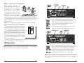
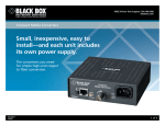
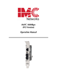
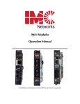
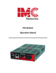
Compact Media Converter
FEDERAL COMMUNICATIONS COMMISSION RADIO
FREQUENCY INTERFERENCE STATEMENT
This equipment has been tested and found to comply with the limits for a Class A computing device, pursuant to Part 15 of the FCC Rules. These limits are designed to provide reasonable protection against harmful interference when the equipment is operated in a commercial environment. This equipment generates, uses and can radiate radio frequency energy and, if not installed and used in accordance with the instruction manual, may cause harmful interference to radio communications. Operation of this equipment in a residential area is
likely to cause harmful interference in which the user will be required to correct the interference at his own expense.
Any changes or modifications not expressly approved by the manufacturer could void the
user's authority to operate the equipment.
The use of non-shielded I/O cables may not guarantee compliance with FCC RFI limits.
This digital apparatus does not exceed the Class A limits for radio noise emission from
digital apparatus set out in the Radio Interference Regulation of the Canadian Department of
Communications.
Le présent appareil numérique n’émet pas de bruits radioélectriques dépassant les limites
applicables aux appareils numériques de classe A prescrites dans le Règlement sur le brouillage radioélectrique publié par le ministère des Communications du Canada.
Installation Guide
LMC001A-R5 - LMC002A-R5 - LMC003A-R5
LMC004A-R5 - LMC007A-R5 - LMC008A-R5
LMC009A-R3
About Compact Media
Converters
The Compact Media Converter series is
IEEE 802.3 compliant, providing a singleconversion between 10 Mbps twisted pair
and either 10 Mbps fiber or thin coax.
Each Compact Media Converter is a 1U
high, standalone unit that includes diagnostic LEDs for each port and an internal
universal (100-240 VAC) power supply.
Q U I C K S T A R T
Introduction
Installation
Configuration
Crossover/Pass-Through
LinkLoss & Pulsing FiberAlert
LED Operation
Technical Support
Warranty
Safety Certifications
1
1
2
2
2
4
6
7
8
The following Compact Media Converter versions are available:
SAFETY CERTIFICATIONS
UL/CUL: Listed to Safety of Information Technology Equipment, Including Electrical Business
Equipment.
CE: The products described herein comply with the Council Directive on
Electromagnetic Compatibility (89/336/EEC) and the Council Directive on
Electrical Equipment Designed for use within Certain Voltage Limits (73/23/EEC).
Certified to Safety of Information Technology Equipment, Including Electrical
Business Equipment. For further details, contact Black Box.
Class 1 Laser product, Luokan 1 Laserlaite,
Laser Klasse 1, Appareil A’Laser de Classe 1
10BT (RJ-45) - 10BFL — 10Base-T twisted pair/10Base-FL 850 nm multimode fiber; includes one RJ-45 connector and one pair ST (LMC001A-R5)
or SC (LMC002A-R5) connectors.
10BT (RJ-45) - 10BFL/1300 — 10Base-T twisted pair/10Base-FL 1300 nm
multi-mode fiber; includes one RJ-45 connector and one pair ST
(LMC003A-R5) or SC (LMC004A-R5) connectors.
10BT (RJ-45) - 10BFL SM/PLUS — 10Base-T twisted pair/10Base-FL 1310 nm
single-mode fiber; includes one RJ-45 connector and one pair ST
(LMC007A-R5) or SC (LMC008A-R5) connectors.
10BT (RJ-45) - 10B2 (BNC) — 10Base-T twisted pair/10Base-2 thin coaxial;
includes one RJ-45 connector and one BNC connector (LMC009A-R3)
Installing Compact Media Converter
1000 Park Drive • Lawrence, PA 15055-1018 USA
TEL: (724) 746-5500 • FAX: (724) 746-0746
E-MAIL: [email protected]
WEB: http://www.blackbox.com
© 2001-2005 Black Box Corporation. All rights reserved.
The information in this document is subject to change without notice. Black Box Corporation assumes no responsibility for any errors
that may appear in this document. Specific brands and product names may be trademarks and are the property of their respective
companies.
Document Number 55-80226BB-01 A0
February 2005
8
Each Compact Media Converters come ready to install; configure after
installation. To install a Compact Media Converter, first make sure that the
unit is placed on a suitable flat surface. Attach the cables between the
Compact Media Converter and each device that will be interconnected, then
plug the unit into a reliable, filtered power source.
IMPORTANT INSTALLATION INFORMATION!
Compact Media Converters do not auto-negotiate, therefore Black Box does NOT recommend connecting them to a switch, media converter or other device that ONLY
auto-negotiates; connect to devices that are 10 Mbps or to devices that you can force
to 10 Mbps.
1
Configuring Compact Media Converter
Once installed, configure Compact Media Converter TP/FO for the following:
• A crossover or pass-through connection for the twisted pair port
• Pulsing FiberAlert
Once installed, configure Compact Media Converter TP/BNC for the following:
• A crossover or pass-through connection for the twisted pair port
• BNC port termination (default = Enabled)
Twisted Pair Crossover/Pass-Through Switch
FIBER OPTIC CLEANING GUIDELINES
Fiber Optic transmitters and receivers are extremely susceptible to contamination by particles of dirt or dust, which can obstruct the optic path and cause performance degradation.
Good system performance requires clean optics and connector ferrules.
1) Use fiber patch cords (or connectors, if you terminate your own fiber) only from a
reputable supplier; low-quality components can cause many hard-to-diagnose problems in an installation.
2) Black Box installs dust caps to ensure factory-clean optical devices. Do not be
remove these protective caps until the moment of connecting the fiber cable to the
device. Assure that the fiber is properly terminated, polished and free of any dust or
dirt, and that the location is as free from dust and dirt as possible.
The twisted pair port on 10 Mbps Compact Media Converters features a pushbutton switch, located next to the twisted pair connector, for selecting a
crossover workstation connection or pass-through repeater/hub connection.
3) Store spare caps in a dust-free environment such as a sealed plastic bag or box so
that when reinstalled they do not introduce any contamination to the optics.
Select a pass-through connection by pressing the push-button IN. A
crossover connection is selected when the push-button is OUT. If uncertain
whether a crossover or pass-through connection is needed, set the push-button to the position that makes the TP LNK (link) LED glow.
5) If you suspect that the optics have been contaminated, alternate between blasting
with clean, dry, compressed air and flushing with isopropyl alcohol to remove particles of dirt.
4) Should it be necessary to disconnect the fiber device, reinstall the protective dust
caps.
ELECTROSTATIC DISCHARGE PRECAUTIONS
Electrostatic discharge (ESD) can cause damage to your add-in modules. Always observe the
following precautions when installing or handling an add-in module or any board assembly.
BNC Port Termination
Compact Media Converter TP/BNC features a 2-position switch next to the
BNC connector that allows a thin coaxial segment to be terminated at the port
without an additional ‘T’ connector and terminator.
If Compact Media Converter TP/BNC is attached
to a mid-point of a thin Ethernet segment, attach
a ‘T’ connector to the BNC port. Termination
must be OFF (disabled). Termination is disabled
when the switch is in the left position. If a thin
Ethernet segment is to be terminated at the
Compact Media Converter TP/BNC, attach the
cable directly to the BNC connector and set the
termination switch to ON (enabled – factory
default) by moving the switch to the right position.
LinkLoss and Pulsing FiberAlert
1) Do not remove unit from its protective packaging until you’re ready to install it.
2) Wear an ESD wrist grounding strap before handling any module or component. If
you do not have a wrist strap, maintain grounded contact with the system unit
throughout any procedure requiring ESD protection.
WARNING! Integrated circuits and fiber optic components are extremely susceptible
to electrostatic discharge damage. Do not handle these components directly unless
you are a qualified service technician and use tools and techniques that conform to
accepted industry practices.
3) Hold boards by the edges only; do not touch the electronic components or gold connectors.
4) After removal, always place the boards on a grounded, static-free surface, ESD pad or
in a proper ESD bag. Do not slide the board over any surface.
WARRANTY
Contact Black Box for warranty information.
LinkLoss and Pulsing FiberAlert are advanced troubleshooting features from
Black Box that can help you locate “silent failures” on your network.
It is vital that you understand exactly how Pulsing FiberAlert and LinkLoss
work and how they will react in your network configuration before attempting to install the enclosed unit.
2
7
Installation Troubleshooting
•
During installation, first test your fiber and twisted pair connections with all
troubleshooting features disabled. Then enable these features, if desired, just
before final installation. This will reduce the features’ interference with testing.
•
To test Compact Media Converter TP/FO by itself, you must have an appropriate fiber patch cable. First, connect Compact Media Converter TP/FO to
the twisted pair device with a twisted pair cable and establish valid link.
Next, loop a single strand of fiber from the transmit port to the receive port
of your media converter. Finally, verify that you have both twisted pair and
fiber link on your media converter.
•
Make sure that you are using the appropriate twisted pair cable or have
the crossover/pass-through button on the media converter set correctly.
•
Interconnection between the Next Generation of 10 Mbps converters
(Compact Media Converter, SNMP Manageable module or unmanaged
module) and their Legacy counterparts is possible. Where possible, however, use Legacy with Legacy product, or Next Generation with Next
Generation product.
General Information
BLACK BOX CUSTOMER SERVICE INFORMATION
Order toll-free in the U.S.: Call 877-877-BBOX
(outside U.S. call 724-746-5500)
FREE technical support, 24 hours a day, 7 days a week:
Call 724-746-5500 or Fax 724-746-0746
Mail order: Black Box Corporation
1000 Park Drive, Lawrence, PA 15055-1018
Web site: www.blackbox.com
E-mail: [email protected]
Installing media converters without understanding the effects of
FiberAlert can cause perfectly functioning units to appear flawed or
even dead!
If you are unfamiliar with Pulsing FiberAlert and LinkLoss, Black Box strongly
encourages you to read the following information. Contact Black Box technical
support for more information and assistance.
ABOUT LINK INTEGRITY
During normal operation, link integrity pulses are transmitted by all
point-to-point Ethernet devices. When an Black Box media converter
receives valid link pulses, it knows that the device to which it is connected
is up and sending pulses, and that the copper or fiber cable coming from
that device is intact. The appropriate “LINK” LED is lit to indicate this. The
Black Box media converter also sends out link pulses from its copper and
fiber transmitters, but normally has no way of knowing whether the cable
to the other device is intact and the link pulses are reaching the other end.
The combination of FiberAlert and LinkLoss allows this information to be
obtained, even when physical access to a remote device (and its link integrity LED) is not available.
WHAT IS FO LINKLOSS?
FO LinkLoss is a troubleshooting feature. When a fault occurs on the fiber
segment (receive side) of a conversion, FO LinkLoss detects the fault and
passes this information to the twisted pair segment. If a media converter is
not receiving a fiber link, FO LinkLoss disables the transmitter on the media
converter's twisted pair port. This results in a loss of link on the device connected to the twisted pair port.
WHAT IS TP LINKLOSS?
SPECIFICATIONS
Environmental
Operating Temperature: 32° - 104° F (0° - 40° C)
Storage Temperature: 0° - 160° F (-20° - 70° C)
Humidity: 5 - 95% (non-condensing)
Power
AC Input Load: 100/240V±10% ~ 50/60 Hz, 0.1/0.05A
Dimensions
TP/FO 1.64”H x 4.75”W x 4.95”D (4.17cm x 12.07cm x 12.57cm)
TP/BNC 1.64"H x 4.75"W x 4.54"D (4.17cm x 12.07cm x 11.53cm)
Shipping weight: 1.3 lbs. (0.6 kg)
6
TP LinkLoss is another troubleshooting feature. When a fault occurs on
the twisted pair segment of a conversion, TP LinkLoss detects the fault and
passes this information to the fiber segment. If a media converter is not
receiving a twisted pair link, TP LinkLoss disables the transmitter on the
media converter's fiber port. This results in a loss of link on the device connected to the fiber port.
C O N F I G U R I N G L I N K L O S S : TP LinkLoss and FO LinkLoss are always
enabled on Compact Media Converter TP/FO.
3
WHAT IS PULSING FIBERALERT?
Pulsing FiberAlert minimizes the
problems associated with the loss of
one strand of fiber. If a strand is
unavailable, the IMC Networks
device at the receiver end notes the
loss of link. The device will stop
transmitting data and start sending
link pulses. Until a valid link is
received, the fiber link LED will be
OFF on the device on the receiver side of the fiber strand with the fault while
the fiber Link LED on the other unit will blink. Pulsing FiberAlert notifies a
local site administrator of a fault, allowing quick determination of where a
cable fault resides.
NOTE: You can enable Pulsing FiberAlert on BOTH sides of a conversion.
CONFIGURING PULSING FIBERALERT
Compact Media Converter TP/FO features an
8-position DIP switch located on the bottom of the
unit for configuring Pulsing FiberAlert after installation. To enable Pulsing FiberAlert, move the switch
labelled “FA Pulse” to the ON position. After configuring the DIP switch, power down the unit and
then power up again for the changes to take
effect. The default setting for the this feature is
shown to the right. Switches 6-8 are factory-configured; DO NOT change.
The LED functions for Compact Media Converter TP/FO are as follows:
TP LINK
Glows green if link is established on the TX port.
TP ACT
Glows amber when data is being passed on the TX port.
FA PULSE
Glows green when Pulsing FiberAlert is enabled.
PWR
Glows green when unit has power.
FO LINK
Glows green when link is established on the FX port.
FO ACT
Glows green if data is being passed on the FX port.
If unsure of how to best implement these features in your configuration,
please contact Black Box Technical Support.
LED Operation
Each Compact Media Converter features diagnostic LEDs. The following illustrations show the location of the LEDs, and other features, on Compact Media
Converter TP/FO and Compact Media Converter TP/BNC.
The LED functions for Compact Media Converter TP/BNC are as follows:
TP RCV
Flickers amber when twisted pair port is receiving data.
TP LNK
Glows green when a twisted pair link is established.
BNC COL Flickers red in normal operation indicating normal
collisions are being detected on the BNC segment.
BNC RCV Flickers amber when BNC port is receiving data.
(Note: On a -20 Compact Media Converter TP/BNC, the TP RCV and BNC RCV LEDs
flicker at a rate proportional to rate that data being passed on the ports. Under low
traffic conditions, the LEDs flicker visibly, while they appear to glow under high traffic conditions.)
4
5