1
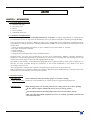
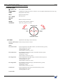
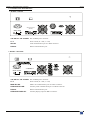
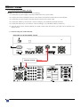
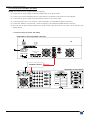
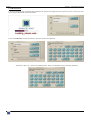
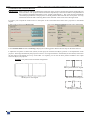
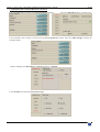
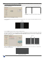
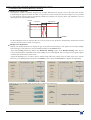
User’s Manual
MODELS: ARC100 & ARC100-B
ANALOG WAY®
AXION – AW5090
EDITION: 09 / 07
AXION
TABLE OF CONTENTS
SAFETY INSTRUCTIONS ...........................................................................................................................................................3
Chapter 1 : INTRODUCTION .......................................................................................................................................................6
1-1. ACCESSORIES SUPPLIED....................................................................................................................................................................6
1-2. GENERAL INFORMATION ..................................................................................................................................................................6
1-3. INSTALLATION.....................................................................................................................................................................................6
1-4. FRONT PANEL DESCRIPTION ............................................................................................................................................................7
1-5. REAR PANEL DESCRIPTION ............................................................................................................................................................10
Chapter 2 : STARTING ...............................................................................................................................................................11
2-1. CONNECTIONS (MODEL ARC100)...................................................................................................................................................11
2-2. CONNECTIONS (MODEL ARC100-B)...............................................................................................................................................12
2-3. SHOW SETUP.......................................................................................................................................................................................13
2-4. SYSTEM CONFIGURATION ..............................................................................................................................................................15
2-5. HOW TO SET A DEVICE TO A SCREEN ..........................................................................................................................................16
2-6. PRESET SETUP ....................................................................................................................................................................................20
Chapter 3 : HOW TO SET A SOFTEDGE SCREEN WITH TWO DEVICES...........................................................................21
3-1. SCREEN SET UP ..................................................................................................................................................................................21
3-2. PROJECTORS CONFIGURATION .....................................................................................................................................................23
Chapter 4 : UPDATING THE DEVICE ......................................................................................................................................27
Chapter 5 : TECHNICAL SPECIFICATIONS ............................................................................................................................28
5-1. COMMUNICATION PORTS................................................................................................................................................................28
5-2. ENVIRONMENTAL .............................................................................................................................................................................28
WARRANTY...............................................................................................................................................................................29
PAGE 2
AXION
SAFETY INSTRUCTIONS
All of the safety and operating instructions should be read before the product is operated and should be retained for further
reference. Please follow all of the warnings on this product and its operating instructions.
CAUTION:
WARNING:
To prevent the risk of electric shock and fire, do not expose this device to rain, humidity or intense
heat sources (such as heaters or direct sunlight). Slots and openings in the device are provided for
ventilation and to avoid overheating. Make sure the device is never placed on or near a textile
surface that could block the openings. Also keep away from excessive dust, vibrations and shocks.
POWER:
Only use the power supply indicated on the device or on the power source. Devices equipped with a
grounding plug should only be used with a grounding type outlet. In no way should this grounding
be modified, avoided or suppressed.
POWER CORD: Use the On (I) / Off (O) switch to power On or Off devices equipped with that switch. All other
devices should be plugged and unplugged from wall outlet. In both cases, please follow these
instructions:
- The power cord of the device should be unplugged from the outlet when left unused for several
days.
- To unplug the device, do not pull on the power cord but always on the plug itself.
- The outlet should always be near the device and easily accessible.
- Power supply cords should be routed so that they are not likely to be walked on or pinched by
items placed upon or against them.
If the power supply cord is damaged, unplug the device. Using the device with a damaged power
supply cord may expose you to electric shocks or other hazards. Verify the condition of the power
supply cords once in a while. Contact your dealer or service center for replacement if damaged.
CONNECTIONS: All inputs and outputs (except for the power input) are TBTS defined under EN60950.
SERVICING:
Do not attempt to service this product yourself by opening or removing covers and screws since it
may expose you to electric shocks or other hazards. Refer all problems to qualified service
personnel.
OPENINGS:
Never push objects of any kind into this product through the openings. If liquids have been spilled or
objects have fallen into the device, unplug it immediately and have it checked by a qualified
technician.
PAGE 3
AXION
INSTRUCTIONS DE SÉCURITÉ
Afin de mieux comprendre le fonctionnement de cet appareil nous vous conseillons de bien lire toutes les consignes de sécurité et de fonctionnement de
l’appareil avant utilisation. Conserver les instructions de sécurité et de fonctionnement afin de pouvoir les consulter ultérieurement. Respecter toutes les
consignes marquées dans la documentation, sur le produit et sur ce document.
ATTENTION : Afin de prévenir tout risque de choc électrique et d’incendie, ne pas exposer cet appareil à la pluie, à l’humidité et aux sources de chaleur
intense.
INSTALLATION : Veillez à assurer une circulation d’air suffisante pour éviter toute surchauffe à l’intérieur de l’appareil. Ne placez pas l’appareil sur ou
proximité de surface textile susceptible d’obstruer les orifices de ventilation. N’installez pas l’appareil à proximité de sources de chaleur comme un radiateur
ou une bouche d’air chaud, ni dans un endroit exposé au rayonnement solaire direct, à des poussières excessives, à des vibrations ou à des chocs mécaniques.
Ceci pourrait provoquer un mauvais fonctionnement et un accident.
ALIMENTATION : Ne faire fonctionner l’appareil qu’avec la source d’alimentation indiquée sur l’appareil ou sur son bloc alimentation. Pour les appareils
équipés d’une alimentation principale avec fil de terre, ils doivent être obligatoirement connectés sur une source équipée d’une mise à la terre efficace. En
aucun cas cette liaison de terre ne devra être modifiée, contournée ou supprimée.
CORDON D’ALIMENTATION : Pour les appareils équipés d’un interrupteur général (Marche I / Arrêt O), la mise sous tension et la mise hors tension se fait
en actionnant cet interrupteur général. Pour les appareils sans interrupteur général, la mise sous tension et la mise hors tension se fait directement en
connectant et déconnectant le cordon d'alimentation de la prise murale.
Dans les 2 cas ci-dessus appliquer les consignes suivantes :
- Débrancher le cordon d'alimentation de la prise murale si vous prévoyez de ne pas utiliser l'appareil pendant quelques jours ou plus.
- Pour débrancher le cordon, tirez le par la fiche. Ne tirez jamais sur le cordon proprement dit.
- La prise d’alimentation doit se trouver à proximité de l’appareil et être aisément accessible.
- Ne laissez pas tomber le cordon d’alimentation et ne posez pas d’objets lourds dessus.
Si le cordon d’alimentation est endommagé, débranchez le immédiatement de la prise murale. Il est dangereux de faire fonctionner cet appareil avec un cordon
endommagé, un câble abîmé peut provoquer un risque d’incendie ou un choc électrique. Vérifier le câble d’alimentation de temps en temps. Contacter votre
revendeur ou le service après vente pour un remplacement.
CONNEXIONS : Toutes les entrées et sorties (exceptée l’entrée secteur) sont de type TBTS (Très Basse Tension de Sécurité) définies selon EN 60950.
RÉPARATION ET MAINTENANCE : L’utilisateur ne doit en aucun cas essayer de procéder aux opérations de dépannage, car l’ouverture des appareils par
retrait des capots ou de toutes autres pièces constituant les boîtiers ainsi que le dévissage des vis apparentes à l’extérieur, risque d’exposer l’utilisateur à des
chocs électriques ou autres dangers. Contacter le service après vente ou votre revendeur ou s’adresser à un personnel qualifié uniquement.
OUVERTURES ET ORIFICES : Les appareils peuvent comporter des ouvertures (aération, fentes, etc...), veuillez ne jamais y introduire d’objets et ne jamais
obstruer ses ouvertures. Si un liquide ou un objet pénètre à l’intérieur de l’appareil, débranchez immédiatement l’appareil et faites le contrôler par un personnel
qualifié avant de le remettre en service.
ISTRUZIONI DI SICUREZZA
Allo scopo di capire meglio il funzionamento di questa apparecchiatura vi consigliamo di leggere bene tutti i consigli di sicurezza e di funzionamento prima
dell’utilizzo. Conservare le istruzioni di sicurezza e di funzionamento al fine di poterle consultare ulteriormente. Seguire tutti i consigli indicati su questo
manuale e sull’apparecchiatura.
ATTENZIONE : Al fine di prevenire qualsiasi rischio di shock elettrico e d’incendio, non esporre l’apparecchiatura a pioggia, umidità e a sorgenti di
eccessivo calore.
INSTALLAZIONE : Assicuratevi che vi sia una sufficiente circolazione d’aria per evitare qualsiasi surriscaldamento all’interno dell’apparecchiatura. Non
collocare l’apparecchiatura in prossimità o su superfici tessili suscettibili di ostruire il funzionamento della ventilazione. Non installate l’apparecchiatura in
prossimità di sorgenti di calore come un radiatore o una fuoruscita d’aria calda, né in un posto esposto direttamente ai raggi del sole, a polvere eccessiva, a
vibrazioni o a shock meccanici. Ció potrebbe provocare un erroneo funzionamento e un incidente.
ALIMENTAZIONE : Far funzionare l’apparecchiatura solo con la sorgente d’alimentazione indicata sull’apparecchiatura o sul suo alimentatore. Per le
apparecchiature fornite di un’alimentazione principale con cavo di terra, queste devono essere obbligatoriamente collegate su una sorgente fornita di una
efficiente messa a terra. In nessun caso questo collegamento potrà essere modificato, sostituito o eliminato.
CAVO DI ALIMENTAZIONE : Per le apparecchiature fornite di interruttore generale (Acceso I / Spento O), l’accensione e lo spegnimento
dell’apparecchiatura si effettuano attraverso l’interruttore. Per le apparecchiature senza interruttore generale, l’accensione e lo spegnimento si effettuano
direttamente inserendo o disinserendo la spina del cavo nella presa murale.
In entrambe i casi applicare i seguenti consigli :
- Disconnettere l’apparecchiatura dalla presa murale se si prevede di non utilizzarla per qualche giorno.
- Per disconnettere il cavo tirare facendo forza sul connettore.
- La presa d’alimentazione deve trovarsi in prossimità dell’apparecchiatura ed essere facilmente accessibile.
- Non far cadere il cavo di alimentazione né appoggiarci sopra degli oggetti pesanti.
Se il cavo di alimentazione é danneggiato, spegnere immediatamente l’apparecchiatura. E’ pericoloso far funzionare questa apparecchiatura con un cavo di
alimentazione danneggiato, un cavo graffiato puó provocare un rischio di incendio o uno shock elettrico. Verificare il cavo di alimentazione spesso. Contattare
il vostro rivenditore o il servizio assistenza per una sostituzione.
CONNESSIONE : Tutti gli ingressi e le uscite (eccetto l’alimentazione) sono di tipo TBTS definite secondo EN 60950.
RIPARAZIONI E ASSISTENZA : L’utilizzatore non deve in nessun caso cercare di riparare l’apparecchiatura, poiché con l’apertura del coperchio metallico o
di qualsiasi altro pezzo costituente la scatola metallica, nonché svitare le viti che appaiono esteriormente, poiché ció puó provocare all’utilizzatore un rischio
di shock elettrico o altri rischi.
APERTURE DI VENTILAZIONE : Le apparecchiature possono comportare delle aperture di ventilazione, si prega di non introdurre mai oggetti o ostruire le
sue fessure. Se un liquido o un oggetto penetra all’interno dell’apparecchiatura, disconnetterla e farla controllare da personale qualificato prima di rimetterla in
servizio.
PAGE 4
AXION
SICHERHEITSHINWEISE
Um den Betrieb dieses Geräts zu verstehen, raten wir Ihnen vor der Inbetriebnahme alle Sicherheits- und Betriebsanweisungen genau zu lesen. Diese
Sicherheits- und Betriebsanweisungen für einen späteren Gebrauch sicher aufbewahren. Alle in den Unterlagen, an dem Gerät und hier angegebenen
Sicherheitsanweisungen einhalten.
VORSICHT & WARNUNG
ACHTUNG: um jegliches Risiko eines Stromschlags oder Feuers zu vermeiden, das Gerät nicht Regen, Feuchtigkeit oder intensiven Wärmequellen aussetzen.
EINBAU : Eine ausreichende Luftzufuhr sicherstellen, um jegliche Überhitzung im Gerät zu vermeiden. Das Gerät nicht auf und in Nähe von
Textiloberflächen, die Belüftungsöffnungen verschließen können, aufstellen. Das Gerät nicht in Nähe von Wärmequellen, wie z.B. Heizkörper oder
Warmluftkappe, aufstellen und es nicht dem direkten Sonnenlicht, übermäßigem Staub, Vibrationen oder mechanischen Stößen aussetzen. Dies kann zu
Betriebsstörungen und Unfällen führen.
STROMVERSORGUNG : Das Gerät nur mit der auf dem Gerät oder dem Netzteil angegebenen Netzspannung betreiben. Geräte mit geerdeter
Hauptstromversorgung müssen an eine Stromquelle mit effizienter Erdung angeschlossen werden. Diese Erdung darf auf keinen Fall geändert, umgangen oder
entfernt werden.
STROMKABEL : Für Geräte mit einem Hauptschalter (Ein/Aus) erfolgt die Stromversorgung und Unterbrechung mittels dieses Hauptschalters. Geräte ohne
Hauptschalter werden durch das Einstecken oder Herausziehen des Steckers in den Wandanschluß ein- oder ausgeschaltet. Für beide Fälle gelten folgende
Richtlinien :
- Den Stecker aus dem Wandanschluß herausziehen wenn Sie das Gerät mehrere Tage oder länger nicht benutzen.
- Das Kabel mittels dem Stecker herausziehen. Niemals am Stromkabel selbst ziehen.
- Die Steckdose muß sich in der Nähe des Geräts befinden und leicht zugänglich sein.
- Das Stromkabel nicht fallen lassen und keine schweren Gegenstände auf es stellen.
Wenn das Stromkabel beschädigt ist, das Gerät sofort abschalten. Es ist gefährlich das Gerät mit einem beschädigten Stromkabel zu betreiben; ein abgenutztes
Kabel kann zu einem Feuer oder Stromschlag führen. Das Stromkabel regelmäßig untersuchen. Für den Ersatz, wenden Sie sich an Ihren Verkäufer oder
Kundendienststelle.
ANSCHLÜSSE : Bei allen Ein- und Ausgängen (außer der Stromversorgung) handelt es sich, gemäß EN 60950, um Sicherheits- Kleinspannunganschlüsse.
REPARATUR UND WARTUNG : Der Benutzer darf keinesfalls versuchen das Gerät selbst zu reparieren, die Öffnung des Geräts durch Abnahme der
Abdeckhaube oder jeglichen anderen Teils des Gehäuses sowie die Entfernung von außen sichtbaren Schrauben zu Stromschlägen oder anderen Gefahren für
den Benutzer führen kann. Wenden Sie sich an Ihren Verkäufer, Ihre Kundendienststelle oder an qualifizierte Fachkräfte.
ÖFFNUNGEN UND MUNDUNGEN : Die Geräte können über Öffnungen verfügen (Belüftung, Schlitze, usw.). Niemals Gegenstände in die Öffnungen
einführen oder die Öffnungen verschließen. Wenn eine Flüssigkeit oder ein Gegenstand in das Gerät gelangt, den Stecker herausziehen und es vor einer neuen
Inbetriebnahme von qualifiziertem Fachpersonal überprüfen lassen.
INSTRUCCIONES DE SEGURIDAD
Para comprender mejor el funcionamiento de este aparato, le recomendamos que lea cuidadosamente todas las consignas de seguridad y de funcionamiento del
aparato antes de usarlo. Conserve las instrucciones de seguridad y de funcionamiento para que pueda consultarlas posteriormente. Respete todas las consignas
indicadas en la documentación, relacionadas con el producto y este documento.
PRECAUCIONES Y OBSERVACIONES
CUIDADO : Para prevenir cualquier riesgo de choque eléctrico y de incendio, no exponga este aparato a la lluvia, a la humedad ni a fuentes de calorintensas.
INSTALACIÓN : Cerciórese de que haya una circulación de aire suficiente para evitar cualquier sobrecalentamiento al interior del aparato. No coloque el
aparato cerca ni sobre una superficie textil que pudiera obstruir los orificios de ventilación. No instale el aparato cerca de fuentes de calor como radiador o
boca de aire caliente, ni en un lugar expuesto a los rayos solares directos o al polvo excesivo, a las vibraciones o a los choques mecánicos. Esto podría
provocar su mal funcionamiento o un accidente.
ALIMENTACIÓN : Ponga a funcionar el aparato únicamente con la fuente de alimentación que se indica en el aparato o en su bloque de alimentación. Los
aparatos equipados con una alimentación principal con hilo de tierra deben estar conectados obligatoriamente a una fuente equipada con una puesta a tierra
eficaz. Por ningún motivo este enlace de tierra deberá ser modificado, cambiado o suprimido.
CABLE DE ALIMENTACIÓN : Para los aparatos equipados con un interruptor general (Marcha I / Paro O), la puesta bajo tensión y la puesta fuera de tensión
se hace accionando este interruptor general.. En los aparatos que no tienen interruptor general, la puesta bajo tensión y la puesta fuera de tensión se hace
directamente conectando y desconectando el enchufe mural.
En ambos casos, se deberá respetar las siguientes consignas:
- Desconectar el aparato del enchufe mural si no piensa utilizarlo durante varios días.
- Para desconectar el cable, tire de la clavija. No tire nunca del cable propiamente dicho.
- El enchufe de alimentación debe estar cerca del aparato y ser de fácil acceso.
- No deje caer el cable de alimentación ni coloque objetos pesados encima de él.
Si el cable de alimentación sufriera algún daño, ponga el aparato inmediatamente fuera de tensión. Es peligroso hacer funcionar este aparato con un cable
averiado, ya que un cable dañado puede provocar un incendio o un choque eléctrico. Verifique el estado del cable de alimentación de vez en cuando. Póngase
en contacto con su distribuidor o con el servicio de posventa si necesita cambiarlo.
CONEXIONES : Todas las entradas y salidas (excepto la entrada del sector) son de tipo TBTS (Muy Baja Tensión de Seguridad) definidas según EN 60950.
REPARACIÓN Y MANTENIMIENTO : Por ningún motivo, el usuario deberá tratar de efectuar operaciones de reparación, ya que si abre los aparatos
retirando el capó o cualquier otra pieza que forma parte de las cajas o si destornilla los tornillos aparentes exteriores, existe el riesgo de producirse una
explosión, choques eléctricos o cualquier otro incidente. Contacte el servicio de posventa, a su distribuidor o dirigirse con personal cualificado únicamente.
ABERTURAS Y ORIFICIOS : Los aparatos pueden contener aberturas (aireación, ranuras, etc.). No introduzca allí ningún objeto ni obstruya nunca estas
aberturas. Si un líquido o un objeto penetra al interior del aparato, desconéctelo y hágalo revisar por personal cualificado antes de ponerlo nuevamente en
servicio.
PAGE 5
AXION
AXION
Chapter 1 : INTRODUCTION
1-1. ACCESSORIES SUPPLIED
•
•
•
•
•
1 AXION (ARC100)
1 AC power cord
2 Stylus
1 User’s Manual.
1 CD-ROM (Tutorials).
1-2. GENERAL INFORMATION
Axion by Analog Way is a Powerful High End Remote Controller to manage, independently or simultaneously,
several Switchers of the iX range either as stand alone boxes or any kind of combination, including soft-edge blending.
Once connected to the iX Switchers, Axion can control up to 6 independent screen configurations in different location,
(single display or multiple projectors in softedge blended mode). Axion controls all the effects and functionalities of the
iX Switchers:
- Control of soft-edge blended presentations, on up to 6 different screens, horizontally or vertically,
- Size, shape, and position of the PIP,
- Transition effects,
- Control of sequences,
- Configuration of each input/output of the controlled Switchers.
Designed with a 16/9 TFT color touchscreen for preview of all configurations, Axion is especially dedicated to
facilitate the setting and programming of presentations on multi-screens. It perfectly fits high end large events with
multi-rooms and very large screens using soft-edge blended technology.
The numerous user friendly, customizable and configurable presets enable preparation of the screen configuration, so
that they are easily accessible during the presentation. A last minute modification is easy thanks to the direct
input/output selection access.
Also equipped with a USB port, the complete configuration of the event can be saved for future use.
With its robust and “Live resistant” buttons and its quality T-Bar and joystick, Axion will help to manage multi-screen,
multi-location live presentations with a total peace of mind.
1-3. INSTALLATION
IMPORTANT:
Please read all the safety instructions (pages 3 to 5) before starting.
• Table Top Mounting: The device can be used directly on a table: the unit is equipped with 4 plastic feet.
IMPORTANT:
• The openings in the rear and side panels are for cooling. Do not cover these openings.
• Be sure that no weight is added to the device in excess of 2 kg (4.4 lbs.).
• The maximum ambient operating temperature must not exceed 40°C (104°F).
• The rack and all mounted equipment in it must be reliably grounded to national and
local electrical codes.
PAGE 6
AXION
Chapter 1 : INTRODUCTION (continued)
1-4. FRONT PANEL DESCRIPTION
CONTROL AREA
TOUCHSCREEN
EDIT AREA
TRANSITION (LIVE) AREA
PAGE 7
Chapter 1 : INTRODUCTION (continued)
AXION
1-4. FRONT PANEL DESCRIPTION (continued)
• CONTROL AREA
12 Vdc 0.1A:
BNC plug for portable lamp.
USB MEMORY:
USB plug for USB memory drive connection. Use for update and parameters back up copy.
HOME:
Displays the home menu.
HELP:
Display the help menu.
, , , :
Moving arrows.
SELECT:
EXIT:
Return to the previous menu.
ENTER:
Selection menu and item validation.
JOYSTICK:
Three axis joystick (X, Y & Z).
Reverse = Up
Y
Z = Size Down
Left
X
Z = Size Up
X
Right
Y
Forward = Down
SETTINGS:
Adjustments and settings selection buttons.
Knobs & SET buttons: Touchscreen parameters controls.
CANCEL:
SAVE:
PIP window POS:
Position adjustment of the PIP window (controlled with the joystick)
-Horizontal position: X axis.
-Vertical position: Y axis.
-Horizontal & vertical size: Z axis.
PIP window size:
Size adjustment of the PIP window (controlled with the joystick).
-Horizontal size: X axis.
-Vertical size: Y axis.
-Horizontal & vertical size: Z axis.
PIP image POS:
Position adjustment of the PIP image (controlled with the joystick).
-Horizontal position: X axis.
-Vertical position: Y axis.
-Horizontal & vertical size: Z axis.
PIP image SIZE:
Size adjustment of the PIP image (controlled with the joystick).
-Horizontal size: X axis.
-Vertical size: Y axis.
-Horizontal & vertical size: Z axis.
LOGO POS:
Position adjustment of the logo (controlled with the joystick).
-Horizontal position: X axis.
-Vertical position: Y axis.
LOGO SIZE:
PAGE 8
AXION
Chapter 1 : INTRODUCTION (continued)
1-4. FRONT PANEL DESCRIPTION (continued)
• EDIT AREA
SCREEN SELECTION: Row of screen selection buttons.
NOTE: Axion can control up to 6 screens. A screen is a projection area and can handle
several machines and video projector (notably in Softedge mode configuration).
1 to 6:
FREEZE SCREEN:
Screen selection.
Freeze the selected screen configuration.
SEQUENCE:
1 to 5:
SHIFT:
SCREEN PRESET:
Row of screen preset buttons.
NOTE: A screen preset is a screen status at one time and is made of Elements.
1 to 30:
Screen preset selection.
ACTUAL PRESET: Actual screen configuration.
NEXT PRESET:
Next screen configuration.
SET 1, SET 2, SET 3: 3 Sets of screen preset allowing obtaining 90 screen presets.
PRESET ELEMENT:
1 to 7:
8 to 13:
14 to 23:
24 to 26:
SET 1, SET 2:
SOURCE / FRAME:
1 to 24:
FREEZE SOURCE:
Row of preset element buttons.
NOTE: Elements are: Backgrounds, Transition type, Logos, Effect duration, Titling, PIP
(picture in picture).
Background element selection.
Title element selection.
PIP element selection.
Logo element selection.
2 Sets of screen preset allowing obtaining 52 screen presets.
Row of source / frame selection buttons.
NOTE: Source selection for Elements creation.
Source / frame selection.
Freeze the selected source.
• TRANSITION (LIVE) AREA
SCREEN (1 to 6):
Screen selection button.
SHIFT:
FADE TO BLACK:
Black screen selection with fade transition.
TAKE BACK:
Return to the last displayed PRESET.
CUT:
CUT transition.
OPEN/CLOSE:
TAKE:
Switching PRESET: allows switching the NEXT PRESET with the ACTUAL PRESET.
T-BAR:
Manual switching PRESET: allows to manually switching the NEXT PRESET with the
ACTUAL PRESET.
NOTE: Some transitions are not executable with the T-BAR, in this case, a cross is
displayed on the blue screen beside the T-BAR.
PAGE 9
Chapter 1 : INTRODUCTION (continued)
AXION
1-5. REAR PANEL DESCRIPTION
• MODEL: ARC100
RS-232
100-250 VAC 1A 50-60 Hz
100-250 VAC 1A 50-60 Hz
(OPTIONAL)
IP/LAN
MODEL : ARC100
100-240 Vac 3A 50-60Hz: IEC standard power connector.
O / I:
Power switch (O = OFF, I = ON)
IP/LAN:
LAN communication port on a RJ45 connector.
RS-232:
RS-232 communication port.
• MODEL: ARC100-B
IP/LAN
100-250 VAC 1A 50-60 Hz
100-250 VAC 1A 50-60 Hz
(OPTIONAL)
MAIN IP/LAN
MODEL : ARC100-B
RS-232
100-240 Vac 3A 50-60Hz: IEC standard power connector.
O / I:
Power switch (O = OFF, I = ON)
MAIN IP/LAN:
Main LAN communication port on a RJ45 connector.
AUXILIARY IP/LAN:
Auxiliary LAN communication port on a RJ45 connector.
RS-232:
RS-232 communication port.
AUXILIARY DISPLAY:
Auxiliary display output on HD15 connector.
PAGE 10
AXION
Chapter 2 : STARTING
2-1. CONNECTIONS (MODEL ARC100)
NOTE: Turn OFF all of your equipment before connecting.
Connect the AC power supply cord to the AXION and to an AC power outlet.
Connect your sources and display devices to the iX devices as describe in the iX Device User's Manual.
Connect the AC power supply cord to the iX devices and to an AC power outlet.
Connect the AXION to your network / router according to your installation (IP/LAN connector).
Connect the iX devices to your network / router according to your installation (IP/LAN connector).
Turn ON the iX device and the AXION (rear panel switch). Then turn ON all your input sources and then your
display devices.
• Connection diagram (model ARC100)
REAR PANEL OF THE AXION (MODEL : ARC100)
6
1
RS-232
100-250 VAC 1A 50-60 Hz
100-250 VAC 1A 50-60 Hz
(OPTIONAL)
IP/LAN
MODEL : ARC100
NETWORK / ROUTER
3
4
5
REAR PANEL OF THE iX DEVICE
INPUTS
OUT 2
6
OUT 1
MAIN
C
C.V
by
HDSDI
& SDI
Y
PAGE 11
Chapter 2 : STARTING (continued)
AXION
2-2. CONNECTIONS (MODEL ARC100-B)
NOTE: Turn OFF all of your equipment before connecting.
Connect the AC power supply cord to the AXION and to an AC power outlet.
Connect your sources and display devices to the iX devices as describe in the iX Device User's Manual.
Connect the AC power supply cord to the iX devices and to an AC power outlet.
Connect the iX devices to your network / router according to your installation (IP/LAN connector).
Connect the AXION to your network / router according to your installation (MAIN IP/LAN connector).
Turn ON the iX device and the AXION (rear panel switch). Then turn ON all your input sources and then your
display devices.
• Connection diagram (model ARC100-B)
REAR PANEL OF THE AXION (MODEL : ARC100-B)
6
IP/LAN
1
100-250 VAC 1A 50-60 Hz
100-250 VAC 1A 50-60 Hz
(OPTIONAL)
MAIN IP/LAN
MODEL : ARC100-B
NETWORK / ROUTER
3
RS-232
5
4
REAR PANEL OF THE iX DEVICE
INPUTS
OUT 2
6
C
C.V
HDSDI
& SDI
Y
PAGE 12
by
OUT 1
MAIN
AXION
Chapter 2 : STARTING (continued)
2-3. SHOW SETUP
• Around one minute after switching ON the AXION, the touchscreen displays the User selection screen. Create a new user
by pressing the New User touchscreen button.
• Press the Edit name touchscreen button to open the touchscreen keyboard…
… And enter a name: my_ name in the example below. Then press ENTER on the touchscreen keyboard.
PAGE 13
Chapter 2 : STARTING (continued)
AXION
2-3. SHOW SETUP (continued)
• If needed, you can set a password, press Edit password to display the touchscreen keyboard…
…. Then choose your password and press Enter on the touchscreen keyboard.
• Select your User account and press Enter. Type your password and press Enter to validate the creation of your User
name.
….The main window is thus displayed.
Shows button: Allows configuring a show.
System button: Allows configuring the AXION.
PAGE 14
Help button:
Allows displaying the Help menu.
Users button:
Allows displaying the User’s
selection menu.
AXION
Chapter 2 : STARTING (continued)
2-4. SYSTEM CONFIGURATION
• Press the System touchscreen button to display the System window…
…then press the Network touchscreen button and set the AXION IP address with the knobs on the right of the touchscreen.
• Press the Axion’s ENTER button. The AXION displays the following message: AXION needs to restart to store the new
IP address as default.
YES: the AXION will restart and keep the IP address as default.
NO: the AXION will keep this IP address for this session only.
PAGE 15
Chapter 2 : STARTING (continued)
AXION
2-5. HOW TO SET A DEVICE TO A SCREEN
• Press the Shows touchscreen button to display the Show window.
• Press Create a new show and type a new show name for example show#1. Then press the Enter touchscreen button.
• The Screen window is thus displayed…
PAGE 16
AXION
Chapter 2 : STARTING (continued)
2-5. HOW TO SET A DEVICE TO A SCREEN (continued)
• Add a device to your screen: Press Screen setup to open the Screen properties window. Then press Edit name and type a
screen name (for example Screen 1). Then press Enter.
• Press Edit devices to add a device to your screen. Then select Add new device and select a device model in the Type
field.
• Then press Edit name to rename your device, for example mixer#1 and press Enter.
PAGE 17
Chapter 2 : STARTING (continued)
AXION
2-5. HOW TO SET A DEVICE TO A SCREEN (continued)
• Select the Connection type (RS232, UDP or TCP) according to your installation. Then press Edit LAN Settings to open
the IP parameters window.
• Select the IP Address corresponding to your device. The Device IP address is available in Control menu > LAN setup.
Verify in the Device that the LAN port is activate (Control menu > RS232/LAN Port > LAN).
• Press several time on the Axion’s ENTER button to return to the Device list window. Then configure the output. Press
Output setup to open the Output adjustment window.
PAGE 18
AXION
Chapter 2 : STARTING (continued)
2-5. HOW TO SET A DEVICE TO A SCREEN (continued)
• Press on the Output resolution arrow to open the output list… Select the needed resolution validate with ENTER and
select the others needed adjustment….
• Then press several times on the Axion’s ENTER button…
…to return to the Screen window.
PAGE 19
Chapter 2 : STARTING (continued)
AXION
2-6. PRESET SETUP
NOTE: Before beginning, open an existing show or create a new one. Wait for the initialization. The touchscreen displays
“Success: all devices connected are initialized”. Then…
Select a SCREEN with the SCREEN SELECTION buttons.
Select a PRESET with the SCREEN PRESET buttons.
NOTE: With the touchscreen display you can give a convenient name to your preset.
Add an element on the selected PRESET: Select a Background button on the PRESET ELEMENT row. The
touchscreen display the transition window: select a transition type with the touchscreen and configure the needed
parameters.
Information about the color of the buttons:
• Screen, Preset, Elements & Source/Frame buttons:
-Bright Yellow button = Selected button
-Dim Yellow button = Programmed button.
-Green button = Selectable button
• Titling bars:
The blue titling bar blinks when an action in this area is
required.
• Take button:
-Bright Red: A preset is ready to commute.
-Blinking: Transition in progress.
• Actual preset / Next preset button:
-Bright Red: Preset available (ready for a transition).
Select a source with the SOURCE/FRAME buttons. The PRESET is now ready. The NEXT PREST button is turn
ON.
NOTE: You can add many elements on each preset. Renew the steps & for adding others elements like a PIP
or a TITLE or a LOGO.
In the transition section: select the corresponding SCREEN button.
Then press TAKE (or activate the T-BAR) to execute the PRESET.
1
2
5
3
4
6
NOTE: Renew the steps , ,
to create others presets. You can create up to 90 presets thanks to the SET 1,
SET 2 & SET 3 buttons. Wheeze: In multi-screens show, you can for example use the SET 1 of PRESET
for the SCREEN 1, the SET 2 of PRESET to the SCREEN 2, etc...
NOTE: Some transitions are not executable with the T-BAR, in this case, a cross is displayed on the blue screen
beside the T-BAR.
PAGE 20
AXION
Chapter 3 : HOW TO SET A SOFTEDGE SCREEN WITH TWO DEVICES
3-1. SCREEN SET UP
• Log on and press the Shows touchscreen button…
…then press Create a new show.
• Type the show’s name (i.e: Show#2) and press Enter.
• Then Press the Screen setup touchscreen button…
…the Screen properties window is thus displayed.
• Press Edit name and type the Screen’s name (i.e: softedge#1) then press Enter.
PAGE 21
Chapter 3 : HOW TO SET A SOFTEDGE SCREEN WITH TWO DEVICES (continued)
AXION
3-1. SCREEN SET UP (continued)
• Press Edit devices to add the 2 devices to your Screen.
• Press the Edit name button…
…then press Add new device and select the device type.
…then type the Device’s name (i.e: mixer left).
• Press ENTER to return to the Device properties window, then press Edit LAN Settings and configure the Device
connection…
• Press the ENTER Axion’s button several time up to display the Device list window then renew the same last operations
for add the second device…
PAGE 22
AXION
Chapter 3 : HOW TO SET A SOFTEDGE SCREEN WITH TWO DEVICES (continued)
3-2. PROJECTORS CONFIGURATION
IMPORTANT: Before doing the following adjustments, make sure the 2 projectors are the same (mark, model and type)
with same lenses. The projector matrices should be imperatively at the same resolution. The parameters of
the 2 projectors should be homogenous (color, gamma, lamp lifetime...). The screen projection should be
vertical and perpendicular to the projectors to avoid geometric distortion like bow or keystone. Use only
mechanical lens shifts and avoid using them in their maximal values. Don't use wide-angle lenses.
• Connect your Computer & Video sources to the inputs of the 2 Di-VentiX and connect the 2 projectors to the MAIN
outputs.
• Select a device and press Output setup
…then set the Output resolution and the others adjustments.
• Press Pattern Main and select Centering to display the centering pattern. Renew the last steps for the others devices.
• Adjust the test pattern in full screen (matrix) of each projector with the auto-adjust, position or size adjustments of the
projector. Then align mechanically the projectors to have a covering area between 10 and 20% (of each matrix) and to have
the test pattern well aligned one on top of the other. As required, you can use the burst pattern available in the output
section to adjust your projector.
Example: Test pattern in horizontal SE configuration.
Top and bottom not aligned.
☺ Projectors well aligned.
Too small covering area.
Edges not paralleled.
PAGE 23
Chapter 3 : HOW TO SET A SOFTEDGE SCREEN WITH TWO DEVICES (continued)
AXION
3-2. PROJECTORS CONFIGURATION (continued)
• Press ENTER button to return to the Screen Properties window…
...then press Edit Input and set up all the inputs.
• Press ENTER Axion’s button to come back to the Screen properties window. Then Press Edit softedge to display the
softedge window.
• Set the Softedge type (Horizontal or Vertical) and device’s Position.
• Press Patterns and select Covering Pattern type.
PAGE 24
AXION
Chapter 3 : HOW TO SET A SOFTEDGE SCREEN WITH TWO DEVICES (continued)
3-2. PROJECTORS CONFIGURATION (continued)
• Press the Covering touchscreen button and set the Covering adjustment so that the test pattern overlaps each other at the
junctions of the projectors.
Example: Test pattern in horizontal SE configuration.
NOTE: Verify that the Softedge is disabling.
• Press the Patterns touchscreen button and turn OFF the test pattern: The covering area will appear brighter than the noncovering areas.
Covering
area
Projected image (before black level adjustment)
• Press the Black touchscreen button to display the Black functions.
-First, you need to adjust the 2 non-covering areas to obtain a uniform dark grey on the entire screen: Select a device and
press ALL (to adjust the 3 colors in the same time) and adjust the Black level. As required, you can also separately adjust
the colors of each projector with the Red (R), Green (G) & Bleu (B) adjustments. Two white lines will appear at the
junctions of the covering areas.
White lines
Projected image (after black level adjustment)
-Then Use the Black start (mixer right) and Black end (mixer left) functions to remove the 2 white lines. A uniform dark
grey image is then displayed.
Uniform projected image.
PAGE 25
Chapter 3 : HOW TO SET A SOFTEDGE SCREEN WITH TWO DEVICES (continued)
AXION
3-2. PROJECTORS CONFIGURATION (continued)
• Softedge curve explanations:
The operation consist of attenuate progressively the light diffused of one projector and in the same time increase
symmetrically the light of the other one. Thus, at any point (X) of the covering area, the sum of light (Y1+Y2) provided
by each projector must be equal to the light that would be provided by one projector alone. The luminance curves of
each projector are represented as follow:
Luma
Right projector
Left projector
100 %
Y2
Y1
X
Screen
On the touchpanel screen we represent the curve of one projector only: the device automatically calculate the inverted
curve for the other projector of the covering area.
• Softedge curve adjustments:
Display your background source or display the grey scale pattern (horizontal grey scale pattern for horizontal softedge
and vertical grey scale pattern for vertical softedge) available in the Patterns menu.
-Press the Covering touchscreen button, then Enable the Softedge (press on the Disable Softedge check box) to
activate the attenuation. The default value of the softedge curves is thus applied. The covering area may appear brighter
or darker than the other areas of the screen.
-Adjust the Softedge Curve in order to have a uniform image: Move the position of the 2 points of the curve with the
knobs (or press and drag directly the points on the Bezier curve). Then press Send Curve to display the adjustments.
• Then Press Axion’s ENTER button several times to return to the Show menu…
PAGE 26
AXION
Chapter 4 : UPDATING THE DEVICE
The AXION can be updated thanks a USB memory stick.
Plug your USB memory drive to your computer, open the disk drive and create a folder named AXION.
Go on our website (http://www.analogway.com) and download the last firmware version to the AXION folder of your
USB memory drive.
Plug the USB memory drive to the USB port of the AXION (Top left of the front panel).
Press the System touchscreen button and press the Update button. Then select the needed version and press the Update
from USB button. The update will start and will restart the AXION automatically in few minutes.
PAGE 27
AXION
Chapter 5 : TECHNICAL SPECIFICATIONS
5-1. COMMUNICATION PORTS
• RS-232 (on DB9 female connector)
Data Rate:
9600 Bauds, 8 data bits, 1 stop bit, no parity bit, and no flow control.
Pin-out:
PIN #
2
3
5
FUNCTIONS
RXD (Receive data)
TXD (Transmit data)
GROUND (Gnd)
DB9 connector
• LAN (on RJ45 connector)
Protocol:
TCP (Transmission Control Protocol) / UDP (User Datagram Protocol).
Data Rate:
10 / 100 Mbps.
5-2. ENVIRONMENTAL
Power Supply:
Internal CE / UL / CSA / IEC 950 (50 W), universal, automatic.
Input: 100 VAC to 250 VAC; 50-60 Hz; I = 1 A Max.
Storage Temperature:
- 25 °C to + 85 °C (- 13 °F to + 185 °F).
Operating temperature: 0 °C to + 50 °C (32 °F to 122 °F).
PAGE 28
Hygrometry:
10% to 80% (without condensation).
Dimensions:
D 395 x W 540 x H 125 mm / D 15.5" x W 21.3" x H 4.95".
Unit: D 265 x W 440 x H 110 mm / D 10.5" x W 17.5" x H 4.35".
Weight:
9 kg / 20 lbs.
AXION
WARRANTY
Analog Way warrants the product against any defects in materials and workmanship for a period of three years from the date of
purchase (back to the factory).
In the event of any malfunction during the warranty period, Analog Way will, at its discretion, repair or replace the defective
units, including free materials and labor.
This warranty does not apply if the product has been:
- improperly installed or abused,
- handled with improper care,
- used or stocked in abnormal conditions,
- modified, opened,
- damaged by fire, war, or Natural disasters (Acts of God).
In no way shall Analog Way be responsible for direct or indirect loss of profit or consequential damages resulting from any
defect in this product.
In case of any problem, get the serial number of the unit, a description of the problem, and then call your authorized dealer.
PAGE 29