1
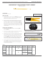
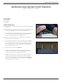
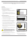
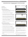
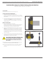
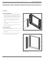
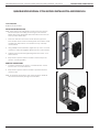
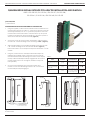
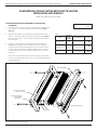
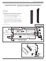
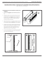
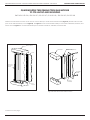
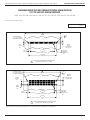
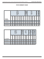
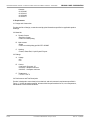
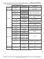
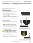
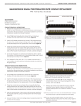
ASSEMBLY, INSTALLATION, AND REMOVAL OF CONTACTS AND MODULES FOR QUADRAPADDLE™ SIGNAL CONTACTS AND MODULES TABLE OF CONTENTS SECTION 1 RECEIVER CONTACT ASSEMBLY INSTRUCTIONS SECTION 2 ITA CONTACT ASSEMBLY INSTRUCTIONS SECTION 3 WIRE WRAP CONTACT TERMINATION INSTRUCTIONS SECTION 4 CONTACT INSTALLATION AND REMOVAL INSTRUCTIONS SECTION 5 MODULE INSTALLATION AND REMOVAL INSTRUCTIONS SECTION 6 PCB INSTALLATION AND REMOVAL INSTRUCTIONS SECTION 7 CROSS REFERENCE TABLES APPENDIX PRODUCT PERFORMANCE SPECIFICATIONS 1/26/10 VIRGINIA PANEL CORPORATION QUADRAPADDLE SIGNAL CONTACTS AND MODULES USER’S MANUAL: SECTION 1 QUADRAPADDLE™ SIGNAL RECEIVER CONTACT ASSEMBLY PART # 610 138 116 TOOLS REQUIRED Crimp Tool, Part # 910 101 125 Dimensions shown: [millimeters] inches CRIMP TOOL SETUP 1. Using the Crimp Tool, Part # 910 101 125 (Figure A), with the wire gauge numbers facing you, squeeze the tool handles together until the ratchet releases; this will open the tool. 2. Place the contact into the crimp die cavity from the rear side of the tool. The contact crimp areas will be facing you. Move the contact up to align the contact on the insulation stop (Figure B). Place contact into the correct wire cavity (24-28 AWG on the left, 22-24 AWG on the right) according to the wire gauge size in Table 1. Squeeze the crimp handles until ratchet clicks one time to hold contact in place. Figure A. Crimp Tool, Part # 910 101 125. 24-28 AWG 22-24 AWG CONTACT SETUP AND CRIMPING 1. Determine the strip length according to wire gauge (Table 1). Strip wire (Figure C). 2. Insert the wire through the insulation stop and into the wire barrel of the contact until it stops against the insulation stop. 3. Holding the wire in place, squeeze the handles together until the tool is completely closed. Continue squeezing, until the last click, to allow the handle to release fully. Remove the contact from the cavity (Figure D). The conductor shall be visible on both ends of the conductor crimp. The insulation crimp should grip securely around the wire insulation without deforming the insulation. 4. Check to make sure the wire meets the minimum pullout force shown in Table 1 and the wire and insulation barrel are within the height and width specifications. Measure the crimp height with an anvil and point micrometer. Figure B. Insulation stop on crimp tool. Note: Larger diameter 24 AWG wire, greater than 0.04” should be crimped using the 22-24 crimp die. [3.18] .125 Figure C. Correctly stripped wire. CONDUCTOR CRIMP INSULATION CRIMP Figure D. Correctly crimped contact. Table 1. WIRE SIZE, AWG CRIMP TOOL LOCATOR STRIP LENGTH DIE IN [MM] 22 0.048 [1.22] 24* 26 INSULATION DIAMETER MAX (IN [MM]) 910 101 125 N/A 28 2-30* 0.125 [3.18] 0.040 [1.02] WIRE BARREL CRIMP PULLOUT FORCE EXTRACTION MAX (IN [MM]) (LBS [N]) TOOL 0.034 - 0.038 [0.86 - 0.96] 10 [44.5] 0.032 - 0.036 [0.81 - 0.91] 8 [35.6] 0.028 - 0.032 [0.71 - 0.81] 4 [17.8] 0.024 - 0.030 [0.61 - 0.76] 910110112 2 [8.9] 1 [4.4]* *Pullout force is for individual wires. 1-1 For more information visit vpc.com 1/26/10 VIRGINIA PANEL CORPORATION QUADRAPADDLE SIGNAL CONTACTS AND MODULES USER’S MANUAL: SECTION 2 QUADRAPADDLE™ SIGNAL ITA CONTACT ASSEMBLY PART # 610 138 109 / 610 138 112 TOOLS REQUIRED Crimp Tool, Part # 910 101 103 Locator, Part # 910 104 140 CRIMP TOOL SETUP 1. Set up the Crimp Tool, Part # 910 101 103 (Figure A), by loosening the latch locking screw (counter-clockwise, until turning stops). Remove any previously used locator. 2. Insert the open end of the Locator, Part # 910 104 140 (Figure B), into the crimp tool locator retainer. Slide the retaining latch toward the locator until the locator is securely locked into place. The locator may have to be twisted to allow the latch to retain it. Tighten the latch locking screw. RETAINING LATCH ASSEMBLY AND LOCKING SCREW LOCATOR RETAINER MICROCRIMP ADJUSTING KNOB MICROCRIMP INDICATOR CRIMP TOOL ADJUSTMENT AND WIRE PREPARATION 1. Adjust the crimp tool setting by pulling the microcrimp adjusting knob and turning it at the same time (clockwise increases, counter-clockwise decreases setting) until the desired setting is achieved on the microcrimp indicator (Table 1). Verify with gauge pin. For more information about gauge pins, visit vpc.com/gaugepins. See calibration instructions for Part # 910 101 102/103 for gauge pin verification instructions. Figure A. Crimp Tool, Part # 910 101 103. 2. Determine the strip length according to wire gauge (Table 1). Strip wire. Figure B. Locator, Part # 910 104 140. CONTACT SETUP AND CRIMPING 1. Insert the contact into the crimp tool and squeeze the handle slightly to hold the contact in position for wire insertion. Figure C. Correctly crimped contact. 2. Insert the stripped wire fully into the contact and squeeze the crimp tool handle until a positive stop is reached. The tool will release and return to a fully “open” position. Remove the crimped contact wire (Figure C). OBSERVE PRECISION RATCHET ACTION BY OPENING AND CLOSING TOOL FULLY SEVERAL TIMES. NOTE THAT THE TOOL CANNOT BE OPENED WITHOUT COMPLETING A CYCLE. NEVER ATTEMPT TO DISASSEMBLE TOOL. NEVER TIGHTEN OR LOOSEN STOP NUTS ON THE BACK OF THE TOOL. NOTE: This contact can also be used to solder wire. Table 1. CONTACT 610138109 610138112 CRIMP TOOL 910101103 910101103 LOCATOR DIE 910104140 910104140 STRIP LENGTH (IN [MM]) 0.200 [5.08] 0.250 [6.35] 0.200 [5.08] INSULATION DIAMETER MAX (IN [MM]) 0.040 [1.02] 0.040 [1.02] WIRE GAUGE CRIMP SETTING (IN [MM]) MAX MIN PULLOUT FORCE (LBS [N]) 22 0.030 [0.76] 0.026 [0.66] 10 [44.5] 24 0.026 [0.66] 0.022 [0.56] 8 [35.6] 2-24* 0.030 [0.76] 0.026 [0.66] 8 [35.6] 2-26* 0.029 [0.74] 0.026 [0.66] 4 [17.8] 26 0.032 [0.81] 0.031 [0.79] 4 [17.8] 28 0.027 [0.68] 0.026 [0.66] 2 [8.9] 30 0.023 [0.58] 0.022 [0.56] 1 [4.4] EXTRACTION TOOL 910110111 * Pullout force is for individual wires 2-1 For more information visit vpc.com 1/26/10 QUADRAPADDLE SIGNAL CONTACTS AND MODULES USER’S MANUAL: SECTION 3 VIRGINIA PANEL CORPORATION QUADRAPADDLE SIGNAL WIRE-WRAP CONTACT TERMINATION PART # 610 138 122 / 610 138 118 TOOLS REQUIRED Wire Stripping Tool Wire-wrap gun Wire-wrap bit ASSEMBLY INSTRUCTIONS NOTE: VPC performs wire-wrap terminations in accordance with IPC-A-620 standards. NOTE: Wire-wraps must be performed with solid wire. Stranded wire will not work for wire wrapping. VPC recommends 26 to 30 AWG wire. 1. Cut and strip the wire. Depending on the style of wire-wrap gun and bit used, the wire is either stripped during the wrapping process or needs to be stripped before the wrapping process. NOTE: Refer to the user manual of your wire-wrap gun to determine in which fashion your tool operates. 2. Insert the wire into the wire slot on the wire-wrap gun. With modified and standard bits insert the wire in the wire slot as deep as possible. With C.S.W. bits the wire has to be inserted all the way through the wire slot until it goes out of the cutting window. The simplified sleeve of the manual tool has no notch. 3. Hold the wire in place by hand (Figure A). 4. Position the terminal hole of the wire-wrap gun on the post to be wrapped. The wire-wrap gun should be parallel with the contact. The wire must continue to be held in place by hand. 5. Engage the wire-wrap gun to wrap the wire. During the wrapping operation, gently press the tool forward onto the wire-wrap post. The turns of the connection have to be nicely wrapped against the other. Do not push too hard. Do not pull backwards. See Figure B for a terminated contact in a module. 3-1 Figure A. Hold the wire in place by hand. Figure B. Completed wrapped wire. For more information visit vpc.com 1/26/10 VIRGINIA PANEL CORPORATION QUADRAPADDLE SIGNAL CONTACTS AND MODULES USER’S MANUAL: SECTION 4 QUADRAPADDLE SIGNAL RECEIVER CONTACT INSTALLATION AND REMOVAL PART # 610 138 116 TOOLS REQUIRED Phillips Screwdriver Flat Blade Screwdriver QuadraPaddle Receiver Extraction Tool, Part # 910 110 112 CONTACT INSTALLATION INSTRUCTIONS 1. Assemble the contact to the respective wire. NOTE: For more information concerning the process of crimping the contact, please see contact assembly instructions in Section 1 of this User’s Manual. 2. Insert the assembled contact into the back (wiring side) of the assembled module (Figure A). The contact can only go into one side. Ensure that the contact is squared up with the corresponding module location. Once in place, pull the wire slightly to ensure that the contact is seated. Figure A. Contacts inserted into the module. CONTACT REMOVAL INSTRUCTIONS 1. 2. 3. Remove the module from the receiver frame. NOTE: For more information concerning the process of removing the module from the receiver frame, see module installation and removal instructions in Section 5 of this User’s Manual. MODULE MOUNTING SCREW 2-56 SCREW MODULE MOUNTING SCREW 2-56 SCREW Use a Phillips head screwdriver to remove the two 2-56 screws located at the top and bottom of the module (Figure B). Insert the flat blade screwdriver into the slot of the module and pry the end of the module using a twisting motion until visible separation is indicated. Repeat on the opposite end of the module (Figure B). 4. Grasp the module halves and apply force in opposite directions, rocking the ends of the module while slightly pulling the top of the module away from the mating bottom section. Be sure to open both sides of the module simultaneously or contacts could be damaged. 5. Place the QuadraPaddle Receiver Extraction Tool, Part # 910 110 112 (Figure C), over the contact to be removed/replaced. Use care to keep the tool perpendicular to the surface of the module, otherwise the tool or the contact could be bent. FLAT BLADE SLOT Figure B. Open both sides of the module simultaneously or pins could be damaged. 6. Once the extraction tool is seated and the retaining tabs on the contact are compressed, depress the plunger. The contact will be pushed out of the rear of the module. DO NOT DEPRESS THE PLUNGER ON THE BACK OF THE EXTRACTION TOOL UNTIL THE TIP OF THE EXTRACTION TOOL HAS FULLY SEATED INTO THE MODULE AND COMPRESSED THE RETAINING RING TABS ON THE CONTACT. 7. Replace the module cap using both hands to push the separated halves together. Replace and tighten the module retaining screws to a maximum torque of 1.5 in-lbs [0.16 Nm]. NOTE: The process shown here uses standard/90 series modules. The same process is used for modules from other series. 4-1 Figure C. Ensure that the tool is kept perpendicular to the module face to avoid damage to the contact or tool. NOTE: If you are using a hybrid module, you may need to reference the User’s Manual for the other contact type for extraction instructions. For more information visit vpc.com 1/26/10 QUADRAPADDLE SIGNAL CONTACTS AND MODULES USER’S MANUAL: SECTION 4 VIRGINIA PANEL CORPORATION QUADRAPADDLE SIGNAL TWIN FEMALE RECEIVER CONTACT REPLACEMENT PART # 610 138 100 TOOLS REQUIRED Phillips Head Screwdriver Flat Blade Screwdriver Tweezers or Needlenose Pliers CONTACT REMOVAL INSTRUCTIONS 1. Remove the module from the receiver frame. NOTE: For more information concerning the process of removing the module from the receiver frame, see module installation and removal instructions in Section 5 of this User’s Manual. 2. Use a Phillips head screwdriver to remove the two 2-56 screws located at the top and bottom of the module (Figure A). 3. Insert the flat blade screwdriver into the slot of the module and pry the end of the module using a twisting motion until visible separation is indicated. Repeat on the opposite end of the module (Figure A). 4. Grasp the module halves and apply force in opposite directions, rocking the ends of the module while slightly pulling the top of the module away from the mating bottom section. Be sure to open both sides of the module simultaneously or contacts could be damaged. 5. Use a pair of tweezers or a small pair of needlenose pliers to grasp the contact. Pull the contact out of the module, taking care to avoid damaging surrounding contacts (Figure B). 6. Figure A. The module is designed with a polarizing feature to make sure the cap is properly aligned. Figure B. Take care to avoid damaging contacts surrounding the one to be removed. If an Adapter Pin, Part #610 138 117/118, needs to be removed, it can be taken out at this point by turning the module over, allowing the pin to fall out. CONTACT INSTALLATION INSTRUCTIONS 1. Remove the module from the receiver frame. NOTE: For more information concerning the process of removing the module from the receiver frame, see module installation and removal instructions in Section 5 of this User’s Manual. 2. Use a Phillips head screwdriver to remove the two 2-56 screws located at the top and bottom of the module (Figure A). 3. Insert the flat blade screwdriver into the slot of the module and pry the end of the module using a twisting motion until visible separation is indicated. Repeat on the opposite end of the module (Figure A). 4. Grasp the module halves and apply force in opposite directions, rocking the ends of the module while slightly pulling the top of the module away from the mating bottom section. Be sure to open both sides of the module simultaneously or contacts could be damaged. Figure C. Ensure the square portion of the contact is aligned with the square opening in the module. 7. If an Adapter Pin, Part #610 138 117/118, needs to be installed, place the pin into the protruding portion of the contact, Part # 610 138 100. 8. Replace the module cap using both hands to push the separated halves together. Replace and tighten the module retaining screws to a maximum torque of 1.5 in-lbs [0.16 Nm]. 5. Align the square portion of the contact with the square opening in the module. Insert the contact into the bottom half of the module (Figure C). NOTE: The process shown here uses standard/90 series modules. The same process is used for modules from other series. 6. Use your thumb or a flat, non-marring surface to press the end of the contact into the module. NOTE: If you are using a hybrid module, you may need to reference the User’s Manual for the other contact type for extraction instructions. 4-2 For more information visit vpc.com 1/26/10 QUADRAPADDLE SIGNAL CONTACTS AND MODULES USER’S MANUAL: SECTION 4 VIRGINIA PANEL CORPORATION QUADRAPADDLE SIGNAL ITA CONTACT INSTALLATION AND REMOVAL PART # 610 138 109 / 610 138 112 / 610 138 115 TOOLS REQUIRED QuadraPaddle ITA Extraction Tool, Part # 910 110 111 CONTACT INSTALLATION INSTRUCTIONS 1. Assemble the contact to the respective wire. NOTE: For more information concerning the process of crimping the contact, see contact assembly instructions in Section 2 of this User’s Manual. 2. Insert the assembled contact into the back (wiring side) of the assembled module (Figure A). The contact can only go into one side. Once in place, pull the wire slightly to ensure that the contact is seated. REMOVAL INSTRUCTIONS 1. Remove the module from the ITA frame. NOTE: For more information concerning the process of removing the module from the ITA frame, see module installation and removal instructions in Section 5 of this User’s Manual. 2. Place the QuadraPaddle ITA Extraction Tool, Part # 910 110 111 (Figure B), over the contact to be removed/replaced. Use care to keep the tool perpendicular to the surface of the module as to not bend the tool or the contact to be removed. Rotate the tool slightly while pushing it into the counter bore on the mating side of the module. 3. Figure A. Contacts inserted into the module. Once the extraction tool is seated properly and the tabs on the retaining ring are compressed, push the plunger and the contact will be pushed out of the rear of the module. DO NOT DEPRESS THE PLUNGER ON THE BACK OF THE EXTRACTION TOOL UNTIL THE TIP OF THE EXTRACTION TOOL HAS BEEN FULLY SEATED INTO THE MODULE AND COMPRESSED THE RETAINING RING TABS ON THE CONTACT. NOTE: The process shown here uses standard/90 series modules. The same process is used for modules from other series. NOTE: If you are using a hybrid module, you may need to reference the User’s Manual for the other contact type for extraction instructions. 4-3 Figure B. Ensure that the tool is kept perpendicular to the module face to avoid damage to the contact or tool. For more information visit vpc.com 1/26/10 VIRGINIA PANEL CORPORATION QUADRAPADDLE SIGNAL CONTACTS AND MODULES USER’S MANUAL: SECTION 4 QUADRAPADDLE SIGNAL ITA FOR WIRE WRAP CONTACT INSTALLATION AND REMOVAL PART # 610 138 122 TOOLS REQUIRED QuadraPaddle Wire Wrap ITA Insertion Tool, Part # 910 113 106 QuadraPaddle ITA Extraction Tool, Part # 910 110 111 CONTACT INSTALLATION INSTRUCTIONS NOTE: For information concerning the process of wrapping the contact, see contact assembly instructions in Section 3 of this User’s Manual. 1. Insert the contact into the back (wiring side) of the module (Figure A). Make sure the contact is inserted as far as possible. 2. Place the QuadraPaddle Wire Wrap ITA Insertion Tool, Part # 910 113 106, onto the contact (Figure B). 3. Using the insertion tool, push the contact into the module until it is fully seated. 4. To ensure the contact is fully seated, pull on the square post lightly. If the contact is not seated, it will be pulled out of the module. Figure A. Contact inserted into the back of the module. INSERTION TOOL CONTACT REMOVAL INSTRUCTIONS 1. Remove the module from the ITA frame. NOTE: For more information concerning the process of removing the module from the ITA frame, see module installation and removal instructions in Section 5 of this User’s Manual. 2. Place the QuadraPaddle ITA Extraction Tool, Part # 910 110 111 (Figure C), over the mating end of the contact to be removed/ replaced. Use care to keep the tool perpendicular to the surface of the module as to not bend the tool or the contact to be removed. Rotate the tool slightly while pushing it into the counter bore on the mating side of the module. 3. Once the extraction tool is seated properly and the tabs on the retaining ring are compressed, push the plunger. The contact will be pushed out of the rear of the module. A DETAIL A Figure B. Ensure that the tool is kept perpendicular to the module face to avoid damage to either the contact or tool. DO NOT DEPRESS THE PLUNGER ON THE BACK OF THE EXTRACTION TOOL UNTIL THE TIP OF THE EXTRACTION TOOL HAS BEEN FULLY SEATED INTO THE MODULE AND COMPRESSED THE RETAINING RING TABS ON THE CONTACT. NOTE: The process shown here uses standard/90 series modules. The same process is used for modules from other series. NOTE: If you are using a hybrid module, you may need to reference the User’s Manual for the other contact type for extraction instructions. Figure C. Ensure that the tool is kept perpendicular to the module face to avoid damage to the contact or tool. 4-4 For more information visit vpc.com 1/26/10 QUADRAPADDLE SIGNAL CONTACTS AND MODULES USER’S MANUAL: SECTION 5 VIRGINIA PANEL CORPORATION QUADRAPADDLE SIGNAL STANDARD/90 SERIES MODULE INSTALLATION AND REMOVAL TOOLS REQUIRED 3 /32 Allen Wrench INSTALLATION INSTRUCTIONS 1. Place the module in the receiver or ITA until the upper and lower module screws touch the mating holes in the inner frame. Ensure that Position 1 is located at the top for systems in which the modules are oriented vertically or to the left for systems in which the modules are oriented horizontally. 2. Using a 3/32 Allen wrench, tighten the top screw 1 to 2 full revolutions, while pushing lightly against the face of the module. 3. Maintain this pressure while tightening the bottom screw 1 to 2 full revolutions. 4. Repeat this sequence until the module is seated. Torque the screw to 4 in-lbs [0.45 Nm]. POSITION 1 REMOVAL INSTRUCTIONS 1. To remove, loosen the top screw 1 to 2 full revolutions. Loosen bottom screw 1 to 2 full revolutions. 2. Repeat this sequence until the module is separated from the receiver or ITA. Figure A. Receiver Module. NOTE: For optimum performance and system longevity, distribute the contact load evenly throughout the module. Figure B. ITA Module. 5-1 For more information visit vpc.com 1/26/10 QUADRAPADDLE SIGNAL CONTACTS AND MODULES USER’S MANUAL: SECTION 5 VIRGINIA PANEL CORPORATION QUADRAPADDLE SIGNAL ICON MODULE INSTALLATION AND REMOVAL TOOLS REQUIRED Phillips Head Screwdriver INSTALLATION INSTRUCTIONS NOTE: The receiver strain relief plate or the ITA cover may need to be removed prior to installing or removing an iCon module. Please refer to the appropriate User’s Manual for instructions on how to perform these steps. 1. Place the module in the receiver or ITA until the upper and lower module screws touch the mating holes in the frame. Install modules such that Position 1 is located at the top of the ITA/ receiver frame. 2. Using a Phillips head screwdriver, tighten the top screw 1 to 2 full revolutions, while pushing lightly against the face of the module. 3. Maintain this pressure while tightening the bottom screw 1 to 2 full revolutions. 4. Repeat this sequence until the module is seated. Torque the screw to 1.5 in-lbs [0.16 Nm]. REMOVAL INSTRUCTIONS 1. To remove, loosen the top screw 1 to 2 full revolutions. Loosen bottom screw 1 to 2 full revolutions. 2. Repeat this sequence until the module is separated from the receiver or ITA. Figure A. Receiver Module. NOTE: For optimum performance and system longevity, distribute the contact load evenly throughout the module. Figure B. ITA Module. 5-2 For more information visit vpc.com 1/26/10 VIRGINIA PANEL CORPORATION QUADRAPADDLE SIGNAL CONTACTS AND MODULES USER’S MANUAL: SECTION 6 QUADRAPADDLE SIGNAL RECEIVER PCB ADAPTER INSTALLATION AND REMOVAL PART # 510 150 125 / 510 150 126 / 510 150 127 / 510 150 128 / 510 150 141 / 510 150 142 / 510 150 148 / 510 150 155 TOOLS REQUIRED 3 /32 Allen Wrench PCB ADAPTER INSTALLATION AND REMOVAL INSTRUCTIONS 1. Using the supplied 3/32 Allen wrench, install the receiver module into the receiver frame with the two 4-40 x 1¼” screws. Note that the screws will extend approximately 0.75” to 1.0” [19-25 mm] beyond the rear of the receiver frame. Ensure that Position 1 is located at the top for systems in which the modules are oriented vertically or to the left for systems in which the modules are oriented horizontally (Figure A). 2. Access the rear of the receiver frame and install the 4-40 stand-offs to the 4-40 X 1¼” module retaining screws according to Table 1 (Figure B). 3. Align the PCB adapter’s two threaded retaining sockets with the 4-40 x 1¼” module retaining screws with stand-offs installed (Figure C). Ensure that Position 1 on the adapter corresponds with Position 1 on the module. 4. Using the 3/32 Allen wrench, carefully install the PCB adapter by tightening the retaining sockets, turning each no more than 1½ to 2 full revolutions before alternating to the other socket. Repeat this step until the PCB adapter is firmly engaged with the receiver module, taking care not to over-tighten, maximum torque of 4 in-lbs [0.45 Nm]. 5. To remove the PCB adapter from the receiver frame and module, use the same alternating method of 1½ to 2 turns until the PCB adapter is fully disengaged. POSITION 1A INDICATOR (MOLDED) Dimensions shown: [millimeters] inches Table 1. RECEIVER FRAME STYLE RECEIVER FRAME THICKNESS STAND-OFF CONFIGURATION ITEMS TO BE USED 9025, 9025TR, 9050, 9075, SL4, S6, G12, and G12x 0.545 [13.84] ⅛" [3.18 mm] stand-off per mounting screw Item Small 90 Series (3,6,10), G2, G6, G10, and G18 (NON-PCB) 0.365 [9.27] /16 " [7.94 mm] stand-off per mounting screw Item G10 (PCB) and G18 (PCB) 0.250 [6.35] Both ⅛" [3.18 mm] and /16 " [7.94 mm] stand-off per mounting screw Item 5 5 VPC RECEIVER FRAME NOT SUPPLIED REF. TABLE 1 VPC RECEIVER FRAME NOT SUPPLIED REF. TABLE 1 1 2 [ ] [ ] [ ] [ ] [ ] VPC RECEIVER FRAME THIS VIEW REPRESENTS CORRECT MODULE ORIENTATION WHEN NOT SUPPLIED PROPERLY PLACED IN A VPC REF. TABLE 1 RECEIVER - NOTE POSTION1A INDICATOR LOCATED AT UPPER LEFT POSITION Figure A. Install receiver module onto receiver frame. 6-1 Figure B. Install proper stand-off. For more information visit vpc.com Figure C. Install PCB adapter. 2/22/10 QUADRAPADDLE SIGNAL CONTACTS AND MODULES USER’S MANUAL: SECTION 6 VIRGINIA PANEL CORPORATION QUADRAPADDLE SIGNAL CUSTOM RECEIVER PCB ADAPTER INSTALLATION AND REMOVAL PART # 510 150 152 / 510 109 315 TOOLS REQUIRED 3 /32 Allen Wrench PCB ADAPTER INSTALLATION AND REMOVAL INSTRUCTIONS 1. Solder the header to PCB (IPC-A-610 standard is recommended for PCB design). The PCB must be manufactured with the header installation area complying with recommended PCB layout (Figure A). 2. Fasten the shroud assembly to the PCB using two 2-56 x .25 flat head screws (Figure B on next page). Torque screws to 2 in-lbs [0.22 Nm]. 3. Using the supplied 3/32 Allen wrench, install the receiver module into the receiver frame with the two 4-40 x 1¼ screws. Torque screws to 4 in-lbs [0.45 Nm]. Note that screw will extend approximately 0.75”-1.0” [19-25 mm] beyond the rear of the receiver frame. Ensure that Position 1 is located at the top for systems in which the modules are oriented vertically or to the left for systems in which the modules are oriented horizontally. Continued on next page... Dimensions shown: [millimeters] inches 140.72 5.540 8.13 .320 124.46 4.900 0.94±0.08 .037±.003 TYP. 192 PLCS. 2.44 2.29 .096 THRU .090 [4.37] .172 X 82 TYP 2 PLCS 7.62 .300 3 EQUAL SPCS. @ [2.54] .100 [.15] .006 A B C PIN 48A LOCATION 16.64 .655 TYP. PIN 1A LOCATION PIN 1D LOCATION PIN 48D LOCATION 10.67 .420 7.62 .300 119.38 4.700 47 EQUAL SPCS. @ [2.54] .100 6.35 .250 5.08 .200 A 125.48 4.940 B RECOMMENDED PCB LAYOUT CONNECTOR MOUNTS OPPOSITE SIDE BOARD THICKNESS = [1.57] .062 DIMENSION TOLERANCE = [.13] .005 UNLESS OTHERWISE SPECIFIED Figure A. Recommended PCB layout. 6-2 For more information visit vpc.com 1/26/10 VIRGINIA PANEL CORPORATION QUADRAPADDLE SIGNAL CONTACTS AND MODULES USER’S MANUAL: SECTION 6 QUADRAPADDLE SIGNAL CUSTOM RECEIVER PCB ADAPTER INSTALLATION AND REMOVAL PART # 510 150 152 / 510 109 315 PCB ADAPTER INSTALLATION AND REMOVAL INSTRUCTIONS, CONTINUED 4. Access the rear of the receiver frame and install the 4-40 stand-offs to the 4-40 X 1¼” module retaining screws according to Table 1 (Figure B). 5. Align the PCB adapter’s two threaded retaining sockets with the 4-40 x 1¼” module retaining screws with stand-offs installed (Figure B). Ensure that Position 1 on the adapter corresponds with Position 1 on the module. 6. 7. Using the 3/32 Allen wrench, carefully install the PCB adapter by tightening the retaining sockets, turning each no more than 1½ to 2 full revolutions before alternating to the other socket. Repeat this step until the PCB adapter is firmly engaged with the receiver module, taking care not to over-tighten. Torque screws to 4 in-lbs [0.45 Nm]. Dimensions shown: [millimeters] inches Table 1. RECEIVER FRAME STYLE RECEIVER FRAME THICKNESS STAND-OFF CONFIGURATION ITEMS TO BE USED 9025, 9025TR, 9050, 9075, SL4, S6, G12, and G12x 0.545 [13.84] ⅛" [3.18 mm] stand-off per mounting screw Item /16 " [7.94 mm] stand-off per mounting screw Item Both ⅛" [3.18 mm] and /16 " [7.94 mm] stand-off per mounting screw Item Small 90 Series (3,6,10), G2, G6, G10, and G18 (NON-PCB) 0.365 [9.27] G10 (PCB) and G18 (PCB) 0.250 [6.35] 5 5 To remove the PCB adapter from the receiver frame and module, use the same alternating method of 1½ to 2 turns until PCB assembly is fully disengaged. SHROUD ASSEMBLY VPC RECEIVER MODULE PART # 510 150 130 VPC RECEIVER FRAME (NOT SUPPLIED) SEE TABLE 1 2 1 CUSTOMER SUPPLIED PCB STAND-OFFS Figure B. Exploded view of assembly. 6-3 For more information visit vpc.com 1/26/10 QUADRAPADDLE SIGNAL CONTACTS AND MODULES USER’S MANUAL: SECTION 6 VIRGINIA PANEL CORPORATION QUADRAPADDLE SIGNAL ITA PCB ADAPTER INSTALLATION AND REMOVAL PART # 510 109 339 / 510 151 123 / 510 151 125 TOOLS REQUIRED 3 /32 Allen Wrench PCB ADAPTER INSTALLATION AND REMOVAL INSTRUCTIONS 1. Install the ITA module into the ITA frame with the two 4-40 double-ended studs. The long end of the stud should pass through the ITA module (Figure A). Ensure that Position 1 is located at the top for systems in which the modules are oriented vertically or to the left for systems in which the modules are oriented horizontally. 2. Align the PCB adapter’s two threaded retaining sockets with the 4-40 double-ended studs (Figure B). Ensure that Position 1 on the adapter corresponds with Position 1 on the module. 3. Using the 3/32 Allen wrench, carefully install the PCB adapter by tightening the retaining sockets, turning each no more than 1½ to 2 full revolutions before alternating to the other socket. Repeat this step until the PCB adapter is firmly engaged with the ITA module, taking care not to over-tighten. Torque screws to 4 in-lbs [0.45 Nm]. 4. To remove the PCB adapter from the ITA frame and module, use the same alternating method of 1½ to 2 turns until the PCB assembly is fully disengaged. VPC ITA FRAME NOT SUPPLIED VPC ITA MODULE PART # 510151107 Figure A. Install ITA module into the ITA frame. 6-4 Figure B. Install the PCB adapter. For more information visit vpc.com 1/26/10 VIRGINIA PANEL CORPORATION QUADRAPADDLE SIGNAL CONTACTS AND MODULES USER’S MANUAL: SECTION 6 QUADRAPADDLE SIGNAL CUSTOM ITA PCB ADAPTER INSTALLATION/REMOVAL PART # 510 151 121 / 510 109 316 TOOLS REQUIRED 3 /32 Allen Wrench PCB ADAPTER INSTALLATION AND REMOVAL INSTRUCTIONS 1. Solder the header to the PCB (IPC-A-610 standard is recommended for PCB design). The PCB must be manufactured with the header installation area complying with the recommended PCB layout (Figure A). 2. A post solder trimming operation is required to shorten the tails in order to eliminate interference between adjacent adapters or strain relief. Trim tails to length shown in Figure B. The dimension represents maximum length after trimming. Tails should be trimmed in accordance with IPC-A-610 standard section 6.5.1. Dimensions shown: [millimeters] inches Continued on next page... 140.72 5.540 8.13 .320 6.35 .250 124.46 4.900 0.94±0.08 .037±.003 TYP. 192 PLCS. [.15] .006 A B C 2.44 2.29 .096 THRU .090 .[4.37] .172 X 82 TYP 2 PLCS A 7.62 .300 3 EQUAL SPCS. @ [2.54] .100 PIN 1A LOCATION 16.64 .655 TYP. PIN 48A LOCATION PIN 48D LOCATION 119.38 4.700 47 EQUAL SPCS. @ [2.54] .100 10.67 .420 7.62 .300 C RECOMMENDED PCB LAYOUT CONNECTOR MOUNTS OPPOSITE SIDE BOARD THICKNESS = [1.57] .062 DIMENSION TOLERANCE = .[.13].005 UNLESS OTHERWISE SPECIFIED PIN 1D LOCATION 5.08 .200 125.48 4.940 B Figure A. Recommended PCB layout. .020 A CUSTOMER SUPPLIED PCB 38.10 1.500 A 2.46 .097 [APPROXIMATE TAIL LENGTH AS SUPPLIED BY VPC] 1.83 .072 [MAXIMUM TRIMMED LENGTH] Figure B. Trim solder tails to length. 6-5 For more information visit vpc.com 2/22/10 QUADRAPADDLE SIGNAL CONTACTS AND MODULES USER’S MANUAL: SECTION 6 VIRGINIA PANEL CORPORATION QUADRAPADDLE SIGNAL CUSTOM ITA PCB ADAPTER INSTALLATION/REMOVAL PART # 510 151 121 / 510 109 316 PCB ADAPTER INSTALLATION AND REMOVAL INSTRUCTIONS, CONTINUED 3. Fasten the shroud assembly to the PCB using two 2-56 x .25” flat head screws (Figure C). Torque screws to 2 in-lbs [0.22 Nm]. 4. Install the ITA module into the ITA frame with the two 4-40 double-ended studs. The long end of the stud should pass through the ITA module (Figure D). Ensure that Position 1 is located at the top for systems in which the modules are oriented vertically or to the left for systems in which the modules are oriented horizontally. 5. Align the PCB adapter’s two threaded retaining sockets with the 4-40 double-ended studs (Figure E). Ensure that Position 1 on the adapter corresponds with Position 1 on the module. 6. Using the 3/32 Allen wrench, carefully install the PCB adapter by tightening the retaining sockets, turning each no more than 1½ to 2 full revolutions before alternating to the other socket. Repeat this step until the PCB adapter is firmly engaged with the ITA module, taking care not to overtighten. Torque screws to 4 in-lbs [0.45 Nm]. 7. Figure C. Attach shroud. To remove the PCB adapter from the ITA frame and module, use the same alternating method of 1½ to 2 turns until the PCB assembly is fully disengaged. VPC ITA FRAME NOT SUPPLIED VPC ITA MODULE PART # 510151107 Figure D. Install ITA module into the ITA frame. 6-6 Figure E. Install the PCB adapter. For more information visit vpc.com 1/26/10 VIRGINIA PANEL CORPORATION QUADRAPADDLE SIGNAL CONTACTS AND MODULES USER’S MANUAL: SECTION 6 QUADRAPADDLE TWIN FEMALE/TWIN MALE MODULE TO PCB LAYOUT AND MOUNTING PART # 510 150 130 / 510 150 137 / 510 151 107 / 510 150 131 / 510 150 135 / 510 151 108 Modules with twin female contacts can be used to connect directly to a PCB mounted male header (Figure A). Modules with twin male posts can be soldered directly to a PCB (Figure B). See Figure C for the recommended PCB layout for modules 510150130, 510150137, and 5101511107. See Figure D for recommended PCB layout for modules 510150131, 510150135, and 510151108. Receiver Frame ITA FRAME MODULE WITH TWIN MALE CONTACTS PCB PCB Module with Twin Female Contacts MOUNTING SCREWS FEMALE HEADERS Male Headers Figure A. Module with Twin Female contacts. Figure B. Module with Twin Male contacts. Continued on next page... 6-7 For more information visit vpc.com 1/26/10 QUADRAPADDLE SIGNAL CONTACTS AND MODULES USER’S MANUAL: SECTION 6 VIRGINIA PANEL CORPORATION QUADRAPADDLE DOUBLE FEMALE/DOUBLE MALE MODULE TO PCB LAYOUT AND MOUNTING PART # 510 150 130 / 510 150 137 / 510 151 107 / 510 150 131 / 510 150 135 / 510 151 108 ...Continued from previous page Dimensions shown: [millimeters] inches 1 5.41 .213 TYP, OPTIONAL HOLES TO ACCESS MODULE MOUNTING SCREWS 7.62 .300 3 EQUAL SPCS. @ [2.54] .100 3.81 .150 TYP. 6.99 .275 119.38 4.700 47 EQUAL SPCS. @ [2.54] .100 133.35 5.250 0.94±0.08 .037±.003 PLATED THRU HOLE TYP. 1 PCB HEIGHT IS DETERMINED BY THE ITA/RECEIVER IN WHICH THE MODULE IS MOUNTED Figure C. Recommended PCB layout for modules 510150130, 510150137, and 5101511107. OPTIONAL HOLES TO ACCESS MODULE MOUNTING SCREWS 1 5.41 .213 TYP. 22.86 .900 9 EQUAL SPCS. @ [2.54] .100 15.24 .600 TYP. 3.81 .150 TYP. 6.99 .275 119.38 4.700 47 EQUAL SPCS. @ [2.54] .100 0.94±0.08 .037±.003 PLATED THRU HOLE TYP. 133.35 5.250 TYP. 1 PCB HEIGHT IS DETERMINED BY THE ITA/RECEIVER IN WHICH THE MODULE IS MOUNTED Figure D. Recommended PCB layout for modules 510150131, 510150135, and 510151108. 6-8 For more information visit vpc.com 1/26/10 7-1 CRIMP TOOL LOCATOR EXTRACTION INSERTION 510 161 101 510 161 102 510 161 107 910 101 103 910 104 140 910 110 111 910 113 106 610 138 109 X X X X X X X X X 610 138 112 X X X X X X X X X 610 138 115 X X X X X X 610 138 122 X X X X X X X X 610 138 118* X X X X X X X ICON ITA MODULES X 510 151 127 610 138 117* 510 151 124 510 151 108 X 510 150 135 510 150 136 510 150 137 510 150 147 X X X X X X X X For more information visit vpc.com X X X X X X X X X EXTRACTION ICON RECEIVER MODULES CASS/ 80 SERIES RECEIVER MODULE STANDARD/ 90 SERIES RECEIVER MODULES 910 110 112 X CRIMP TOOL X 910 101 125 510 160 112 510 160 107 510 160 105 510 160 102 510 160 101 510 114 131 510 150 131 510 150 116 510 150 130 610 138 100 CASS/ 80 SERIES ITA MODULE 510 114 131 STANDARD/ 90 SRIES ITA MODULES 610 138 116 510 150 115 RECEIVER CONTACTS 510 151 107 510 151 106 ITA CONTACTS 510 151 105 QUADRAPADDLE SIGNAL CONTACTS AND MODULES USER’S MANUAL: SECTION 7 VIRGINIA PANEL CORPORATION CROSS REFERENCE TABLES X X *May be used with Part # 610 138 100 X 1/26/10 QUADRAPADDLE SIGNAL CONTACTS AND MODULES USER’S MANUAL: APPENDIX VIRGINIA PANEL CORPORATION Product Performance Specifications QuadraPaddle Connector 1. Scope 1.1 Content This specification covers the performance, tests and quality requirements for the QuadraPaddle Connector and connector system. This contact is a separable electrical connection device for mating to a .025 inch round or square post. The crimped type of contact can be used with 22 to 30 AWG wire sizes. QuadraPaddle contacts are to be used with connector modules with .100 inch centerline spacing. 1.2 Qualification Testing When tests are performed on subject product line, the following procedures shall be used: All inspections shall be performed using applicable inspection plans and product drawings. Upon completion of qualification testing, this specification will be assigned a number and be classified, as a Product Qualification Report which will be identified in section 2. 2. Applicable Documents 2.1 Content The following documents form a part of this specification to the extent specified herein. Unless otherwise specified, the latest edition of the document applies. In the event of a conflict between requirements of this specification and product drawing, product drawing will take precedence. In the event of a conflict between requirements of this specification and referenced documents, this specification shall take precedence. 2.2 Documents A. EIA Standards • EIA-264-05 • EIA-264-06 • EIA-264-09 • EIA-264-13 • EIA-264-17 • EIA-264-20 • EIA-264-21 • EIA-264-29 B. Qualification Test Plan • 2003-116 C. Product Qualification Report • VPC Test Report #2003-117 • VPC Test Report #2009-208 D. Product Drawings Housings • 510150130 • 510150115 • 510150105 1 of 6 For more information visit vpc.com Rev. 5 – 9/22/09 QUADRAPADDLE SIGNAL CONTACTS AND MODULES USER’S MANUAL: APPENDIX VIRGINIA PANEL CORPORATION Contacts • 610138100 • 610138116 • 610138109 • 610138117 3. Requirements 3.1 Design and Construction Product shall be of design, construction and physical dimensions specified on applicable product drawings. 3.2 Materials A. Female Contact • Beryllium Copper • Gold over nickel plating B. Male contact • Brass • Gold over nickel plating per MIL-DTL-45204D C. Housing • Plastic, Glass filled, Liquid Crystal Polymer 3.3 Ratings A. Voltage • AC • DC B. Current • Low Level- See para. 3.5 • 22 AWG: 5 ampere maximum • 28 AWG: 1.4 ampere maximum C. Temperature • -50oC to +105oC 3.4 Performance and Test Description Product is designed to meet electrical, mechanical, and environmental requirements specified in Figure 1. Unless otherwise specified, all tests should be performed at free air, room temperature, and ambient environmental conditions. 2 of 6 For more information visit vpc.com Rev. 5 – 9/22/09 QUADRAPADDLE SIGNAL CONTACTS AND MODULES USER’S MANUAL: APPENDIX VIRGINIA PANEL CORPORATION 3.5 Test Requirements and Procedures Summary Test Description Preliminary Requirement Procedure Examination of Product Meets requirements of product drawing Visual, dimensional, and functional examination per applicable quality inspection plan Termination Resistance: Double Female Contact Termination Resistance: Wire Crimped Contact 25 mΩ maximum initial Environmental 35 mΩ maximum final 5000 MΩ minimum initial 1000 MΩ minimum final Dielectric Withstanding Voltage 1500 VDC test voltage at sea level EIA-364-20: Test between adjacent contacts at 0.5 mA Current Rating 30° C maximum temperature rise Test temperature rise in housing loaded with contacts subjected to a variable current – see Figure 4 Low Level Voltage drop of ≤ 3 μV EIA-364-06: Test signal of 5 mVDC at 100μA Bandwidth Maximum rolloff of -3dB DC to 1.2 GHz - see Figure 5 See test sequence: Figure 6 Contact shall not dislodge Contact shall not dislodge Force to insert contacts into module ≤ 1.0 lbs EIA-364-09: Mate and unmate sample for 20000 cycles EIA-364-29: Apply axial load of 3 lbs to contact Force to insert contacts into module ≤ 2.0 lbs EIA-364-05 Durability Mechanical 25 mΩ maximum initial EIA-364-06: Subject mated contacts assembled in housing to 50 mV maximum open circuit at 100 mA maximum. See figures 2 and 3. EIA-364-21: Test between adjacent contacts assembled in housing at 500VDC Insulation Resistance Electrical 35 mΩ maximum final Retention Force: Wire Crimp Contact Retention Force: ITA Contact Insertion Force: Wire Crimp Contact Insertion Force: Double Female Contact Insertion Force: ITA Contact Force to insert contacts into module ≤ 1.0 lbs Mating Force 1.5 to 2.5 ounces force per contact using a Ø 0.025" round pin Unmating Force ≤ 2.5 ounces force per contact using Ø .025" round pin Temperature Life See test sequence: Figure 6 EIA-364-13: Measure force necessary to mate samples at a normal rate of engagement of the ITA EIA-364-13: Measure force necessary to unmate samples at a normal rate of disengagement of the ITA EIA-364-17: Subject mated samples to temperature life at 105°C for 500 hours Figure 1. Test Requirements and Procedure Summary 3 of 6 For more information visit vpc.com Rev. 5 – 9/22/09 QUADRAPADDLE SIGNAL CONTACTS AND MODULES USER’S MANUAL: APPENDIX VIRGINIA PANEL CORPORATION 3.6 Termination Resistance Measurement Setup Figure 2. Termination Resistance Measurement Points - Double Female contact Figure 3. Termination Resistance Measurement Points - Wire Crimp Contact 3.7 Current Rating Graph Figure 4. Temperature Rise vs. Current 4 of 6 For more information visit vpc.com Rev. 5 – 9/22/09 QUADRAPADDLE SIGNAL CONTACTS AND MODULES USER’S MANUAL: APPENDIX VIRGINIA PANEL CORPORATION 3.8 Bandwidth Graph dB Loss Frequency (GHz) Figure 5. Male to Female QuadraPaddle connectors de-embedded (-3 dB at 1.2 GHz) 3.9 Product Qualification and Requalification Test Sequence Test or Examination Examination of Product Termination Resistance Insulation Resistance Dielectric Withstanding Voltage Durability Contact Retention Mating Force Unmating Force Temperature Life Current Rating Contact Installation Force Bandwidth I 1, 7 3, 5 II 1, 5 2, 4 Test Group III 1, 4 IV 1 V 1 2 3 4 3 2 6 3 5 2 2 Figure 6. Test Sequence Numbers indicate the sequence in which the tests are performed. For test group sample selection see 4.1 A. 5 of 6 For more information visit vpc.com Rev. 5 – 9/22/09 QUADRAPADDLE SIGNAL CONTACTS AND MODULES USER’S MANUAL: APPENDIX VIRGINIA PANEL CORPORATION 4. Quality Assurance Provisions 4.1 Qualification Testing A. Sample Selection Samples shall be prepared in accordance with applicable instruction sheets and shall be selected at random from current production. All test groups shall each consist of a minimum of 5 connectors containing at least 30 contacts total each and equal posts to mate with receptacles. Test group 1 shall have both minimum and maximum position size connectors. B. Test Sequence Qualification inspection shall be verified by testing samples as specified in Figure 6. 4.2 Requalification Testing If changes significantly affecting form, fit or function are made to product or manufacturing process, product assurance shall coordinate requalification testing, consisting of all or part of original testing sequence as determined by development/product, quality and reliability engineering. 4.3 Acceptance Acceptance is based on verification that product meets requirements of Figure 1. Failures attributed to equipment, test set-up or operator deficiencies shall not disqualify product. When product failure occurs, corrective action shall be taken and samples resubmitted for qualification. Testing to confirm corrective action is required before resubmittal. 4.4 Quality Conformance Inspection A Certificate of Conformance (C of C) dimensional inspection must be completed for all samples prior to Qualification testing. The applicable quality inspection plan will specify sampling acceptable quality level to be used. Dimensional and functional requirements shall be in accordance with applicable product drawing and this specification. Rev 1 2 3 4 5 6 of 6 Date 9/2/03 1/22/08 1/23/09 6/30/09 9/22/09 Rev Change Original release Updated and Formatted Updated Current Specification Add Bandwidth Specification Updated For more information visit vpc.com Prepared By Darryl Ashby Eric Husted Eric Husted Eric Husted Eric Husted Rev. 5 – 9/22/09