1
VIRGINIA PANEL CORPORATION
MINI COAXIAL CONTACTS AND MODULES USER’S MANUAL: SECTION 1
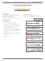
MINI COAXIAL RECEIVER CONTACT ASSEMBLY
PART # 610 104 141 FOR RG178
TOOLS REQUIRED
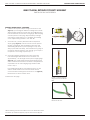
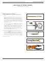
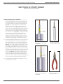
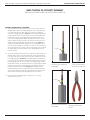
Center Conductor Enlarging Tool, Part # 910 121 143
Center Conductor Forming Tool, Part # 910 121 119
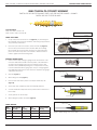
Hex Crimp Tool, Part # 910 101 115
Inspection Depth Gauge, Part # 910 121 156
Calibration Plug, Part # 414 854 104 (Included in Part # 910 121 156)
Weight Gauge Kit, Part # 910 121 131
4.0 oz. Weight, Part # 432 026 000 (included in Part # 910 121 131)
0.5 oz. Weight, Part # 432 025 000 (included in Part # 910 121 131)
Dimensions shown: [millimeters]
ASSEMBLY INSTRUCTIONS
[16.51]
0.65
[9.90]
0.39
1.
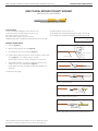
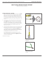
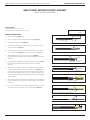
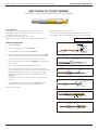
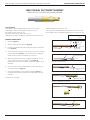
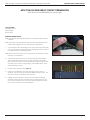
Strip wire (Figure A).
2.
Slide the crimp ring onto the wire (Figure B).
3.
Turn braid back over outer insulation (Figure C).
4.
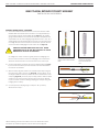
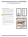
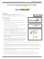
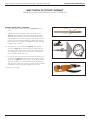
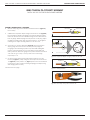
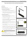
Slide the spacer tube over the dielectric to edge of the braid
(Figure D). Use heat gun to shrink spacer to hold onto dielectric.
5.
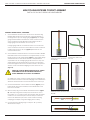
Tin wire and solder into center conductor and clean (Figure E).
VPC solders per IPC’S J-STD-001.
NOTE: Center conductor and dielectric must touch. Solder should
be visible in the hole.
6.
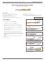
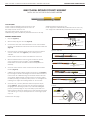
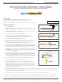
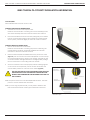
Slide shield conductor over center conductor until the center
conductor stops in the Teflon® shield. To ensure that the coaxial
cable has been fully inserted into the contact, a gap between the
shielding and the contact should exist after achieving positive stop
(Figure F).
NOTE: Shield conductor and Teflon insulator are supplied as an
assembly.
OUTER INSULATION
BRAID
DIELECTRIC
inches
[4.32]
0.17
CONDUCTOR
WIRE
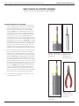
Figure A. Strip wire.
Figure B. Crimp ring.
Figure C. Turn braid back.
Continued on next page...
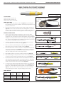
Figure D. Spacer tube.
Figure E. Ensure solder is visible in hole.
Figure F. Shield conductor.
1-4
For more information visit vpc.com
9/24/10