1
User Manual
IC-485S /IC-485SI
Read this guide thoroughly and follow the installation and operation
procedures carefully in order to prevent any damage to the units and/or
any devices that connect to them.
This package contains:
M 1 IC-485S or IC-485SI Interface Converter
M 1 Power Adapter (DC 9V; 300mA)
M 1 User Manual
If anything is damaged or missing, contact your dealer.
©
®
Copyright 2005 ATEN International Co., Ltd.
Manual Part No. PAPE-0075-201
Printed in China 01/2005
All brand names and trademarks are the registered property of their respective owners.
2005-01-04
Warning! This equipment has been tested and found to comply
with the limits for a Class A digital device, pursuant to Subpart J
of Part 15 of the FCC Rules. These limits are designed to provide
reasonable protection against harmful interference when the
equipment is operated in a commercial environment. This
equipment generates, uses and can radiate radio frequency
energy and, if not installed and used in accordance with the
instruction manual, may cause interference to radio
communications. Operation of this equipment in a residential area
is likely to cause harmful interference, in which case the user will
be required to correct the interference at his own expense.
2005-01-04
Overview
Although RS-232 serial ports are found on almost every computer,
because of their slow transmission speeds, limited range, and limited
networking capabilities, they are not an effective solution for industrial
strength long distance communications systems.
Systems based on the RS-485 standard, however, utilize different
voltage lines for the data and control signals, so they are not subject to
the RS-232 limitations.
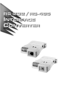
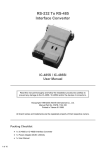
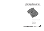
The IC-485S / IC-485SI is a bidirectional converter that transparently
converts RS-232 signals to RS-485 signals (and vice versa). The
IC-485S / IC-485SI provides Point-to-Point; Multidrop; and Simplex
operations over distances of up to 1200 m (4000 ft.), thus permitting the
creation of reliable long distance data communications systems using
standard computer hardware.
-1-
2005-01-04
Switch Configuration
The IC-485S / IC-485SI’s operating mode parameters are set with two
slide switches:
M SW1 sets the Device Mode
M SW2 sets the Transmitting and Receiving Mode
IC-485S Switch Settings
SW 1
RS-232 DB-25 Female Connecter
SW 2
Terminal Block
Spare
Power Jack
RJ-11
Setting
Position
SW1
SW2
1
DCE
TxO, RxON
2
DTE
TxRTS, RxRTS
3
Monitor
TxRTS, RxON
-2-
2005-01-04
IC-485SI Switch Settings
SW 1
RS-232 DB-25 Female Connecter
SW 2
Terminal Block
Power Jack
Grnd. Tab
Setting
Position
SW1
SW2
1
DTE
TxO, RxON
2
DCE
TxRTS, RxRTS
3
X
TxRTS, RxON
-3-
2005-01-04
Terminology
Explanations of the SW1 and SW2 terms are given in the table below:
Term
Explanation
DCE
Data Communications Equipment; if the IC-485S /
IC-485SI is going to be plugged into a DTE device,
the IC-485S / IC-485SI must be set to DCE.
DTE
Data Terminating Equipment; if the IC-485S /
IC-485SI is going to be plugged into a DCE device,
the IC-485S / IC-485SI must be set to DTE.
TxON, RxON
This setting is used in Point-to-Point operations, in
which the unit is always in Transmitting and
Receiving Mode.
TxRTS, RxRTS
This setting is used in Multidrop operations, in
which the unit is in Transmitting Mode when the
RTS signal is high, and is in Receiving Mode when
the RTS signal is low.
TxRTS, RxON
This setting is used in Multidrop Full Duplex
operations to monitor the RS-485 line signals.
Receiving Mode is always ON. Transmitting mode
only occurs when the RTS signal is high.
-4-
2005-01-04
Operating Modes
The IC-485S / IC-485SI supports four operating modes: Point-to-Point;
Multidrop; Simplex; and Monitor (IC-485S only). Point-to-Point and
Multidrop can be configured for Full or Half Duplex. Each of the
operating modes is explained in the sections that follow.
Point-to-Point
A Point-to-Point configuration is one in which two devices, located at
two different places are linked for communication by a pair of IC-485S
or IC-485SI units. There are two configurations: Point-to-Point Full
Duplex, and Point-to-Point Half Duplex.
1. Point-to-Point Full Duplex
M Point-to-Point Full Duplex uses reverse four wire cabling, as
shown in the diagram below:
DB-25
Connect
to PC#1's
COM port
DB-25
T+
TRR+
R+
RTT+
Connect
to PC#2's
COM port
M For both IC-485S / IC-485SI units, set SW1 to DCE or DTE depending on what type of device the IC-485S / IC-485SI will plug
into (if it will plug into a DCE device, configure it for DTE, and
vice versa).
M For both IC-485S / IC-485SI units, set SW2 to TxON, RxON.
-5-
2005-01-04
2. Point-to-Point 2 Wire Half Duplex
M Point-to-Point Half Duplex uses straight through four wire cabling, as shown in the diagram below:
DB-25
Connect
to PC#1's
COM port
DB-25
T+
TRR+
R+
RTT+
Connect
to PC#2's
COM port
M For both IC-485S / IC-485SI units, set SW1 to DCE or DTE depending on what type of device the IC-485S / IC-485SI will plug
into (if it will plug into a DCE device, configure it for DTE, and
vice versa).
M For both IC-485S / IC-485SI units, set SW2 to TxRTS, RxRTS.
Note: The RTS signal is controlled by an external software
command. The IC-485S / IC-485SI has no capability to
control this signal by itself.
-6-
2005-01-04
Multidrop
A Multidrop configuration is one in which more than two devices are
linked for communication using several IC-485S / IC-485SI units.
One of the devices that one of the IC-485S / IC-485SIs connects to is
designated as the Master device. All the remaining devices that the rest
of the IC-485S / IC-485SIs connect to are designated as Slave devices.
There are two configurations: Multidrop Full Duplex, and Multidrop Half
Duplex.
1. Multidrop 4 Wire Full Duplex
M Multidrop Full Duplex uses reverse four wire cabling to link all the
connected IC-485S / IC-485SI units:
PC1
COM1/
COM2
Slave 1
R+
RTT+
Master
T+
TRR+
Slave 2
R+
RTT+
.
.
.
Slave 31
PC2
COM1/
COM2
PC3
COM1/
COM2
M For all IC-485S / IC-485SI units, set SW1 to DCE or DTE depending on what type of device the IC-485S / IC-485SI will plug into (if
it will plug into a DCE device, configure it for DTE, and vice
versa).
M For the Master unit, set SW2 to TxON, RxON.
M For all Slave units, set SW2 to TxRTS, RxON.
-7-
2005-01-04
2. Multidrop Half Duplex
M Multidrop Half Duplex uses straight-through four wire cabling, to
link all the connected IC-485S / IC-485SI units:
PC1
COM1/
COM2
Slave 1
R+
RTT+
Master
T+
TRR+
Slave 2
R+
RTT+
Slave 3
R+
RTT+
.
.
Slave 31
PC2
COM1/
COM2
PC3
COM1/
COM2
PC4
COM1/
COM2
M For all IC-485S / IC-485SI units, set SW1 to DCE or DTE depending on what type of device the IC-485S / IC-485SI will plug into (if
it will plug into a DCE device, configure it for DTE, and vice
versa).
M For all IC-485S / IC-485SI units set SW2 to TxRTS, RxRTS.
Note: The RTS signal is controlled by an external software
command. The IC-485S / IC-485SI has no capability to
control this signal by itself.
-8-
2005-01-04
Simplex
A Simplex configuration is one in which more than two devices are
linked for communication using several IC-485S / IC-485SI units in a
manner similar to Multidrop. The difference is that in a Simplex
configuration, the Master device can only talk, and the Slave devices
can only listen.
M Simplex uses reverse two wire cabling to link all the connected
IC-485S / IC-485SI units, as shown in the figure below:
PC1
COM1/
COM2
Master
T+
TRR+
Slave 1
R+
PC2
COM1/
COM2
RTT+
Slave 2
R+
PC3
COM1/
COM2
RTT+
Slave 3
R+
PC4
COM1/
COM2
RTT+
:
:
Slave 31
M For all IC-485S / IC-485SI units, set SW1 to DCE or DTE depending on what type of device the IC-485S / IC-485SI will plug into (if
it will plug into a DCE device, configure it for DTE, and vice
versa).
M For all of the units (Master and Slave), set SW2 to TxON, RxON.
-9-
2005-01-04
Monitor (IC-485S only)
With Monitor Mode, the RS-485S can be wired to the lines of an
RS-485 or RS-422 device to monitor the line signals. In this
configuration, the RS-485S changes the functions of T+ and T- to R’+
and R’- respectively.
Device 1
T+
TRR+
Device 2
R+
RTT+
IC-485S
T+ (R'+)
T- (R'-)
RR+
PC
COM1/
COM2
M Set SW1 to Monitor.
M Set SW2 to TxRTS, RxON
Note: 1. The RTS must be Low in Monitor Mode.
2. The R+ and R- signals are converted and linked to the
RS-232 port, DB-25 pin 3. The R’+ and R’- (T+ and T-)
signals are converted and linked to the RS-232 port,
DB-25 pin 2.
- 10 -
2005-01-04
Installation
1. Set each IC-485S / IC-485SI’s configuration switches according to
the information provided in the Switch Configuration and Operating
Modes sections.
2. Plug the IC-485S / IC-485SI’s DB-25 female connector into the
computer’s RS-232C port.
3. Connect the IC-485S / IC-485SI units to each other:
M Use two or four wire twisted pair cable in a reverse or straight
through configuration according to the information provided in the
Switch Configuration and Operating Modes sections.
M For the IC-485S, you may use either the RJ-11 telephone socket,
or wire directly to the Terminal Block. (See the Terminal Block
section for pin assignment details.)
M For the IC-485SI, you must ground the device by connecting a
grounding wire from the Grounding Tab to the grounding source.
4. Power on the computers. The units are now ready for operation.
- 11 -
2005-01-04
Appendix
The Terminal Block
The four screw terminal block has different pin assignments depending
on the operating mode:
M In DCE/DTE mode, terminals 1 (+V) and 2 (-V) are configured to
transmit data (the transmitter); while terminals 3 (-V) and 4 (+V) are
configured to receive data (the receiver).
M In Monitor mode (IC-485S only), terminals 1 and 2 are, respectively,
the positive and negative of receiver 1; while terminals 3 and 4 are,
respectively, the positive and negative of receiver 2.
Pin
DCE/DTE
Monitor
1
Transmitter +V
Receiver 1 +V
2
Transmitter -V
Receiver 1 -V
3
Receiver -V
Receiver 2 -V
4
Receiver +V
Receiver 2 +V
- 12 -
2005-01-04
DCE / DTE Connection Table
Because of the polarity of the communication signals, a DTE configured
device must connect to a DCE configured device. The shaded area in
the figure below is an example of a DTE to DCE connection:
Device's Connector Pin #
DCE
DTE
DB-9
DB-9
2
3
8
7
4
6
5
3
2
7
8
6
4
5
DCE
Cable
DB-25 DB-25
3
2
5
4
20
6
7
2
3
4
5
6
20
7
IC-485ASI
25/25 or
9/25 pin
DTE
Tx
Rx
Rx
Tx
RTS
CTS
CTS
RTS
DSR
DTR
DTR
DSR
GND
DCE
DTE
DB-25 DB-25
2
3
4
5
6
20
7
3
2
5
4
20
6
7
Self Test
To test the internal circuit of the interface converter, connect a dumb
terminal to the unit and do the following:
1. Set SW1 to DCE (if the dumb terminal is configured for DCE).
2. Set SW2 to TxON, RxON.
3. Connect a wire from pin 1 (Tx+) to pin 4 (Rx+)
4. Connect a wire from pin 2 (Tx-) to pin 3 (Rx-)
5. Set the terminal to full duplex and enter data.
If the data displays on the screen, the internal circuit is operational.
- 13 -
2005-01-04
Troubleshooting
Problem
Data Transmission
Failure
Action
Check that the power adapter is plugged in
and working properly.
Check that the IC-485S / IC-485SI units are
securely plugged into the computers’ serial
ports.
Check that the cables are properly set up and
properly connected.
Check that SW1 and SW2 are set properly.
Data Loss or Error
Check that the Data Rate and Data Format
are the same for all devices.
Limited Warranty
IN NO EVENT SHALL THE DIRECT VENDOR S LIABILITY EXCEED
THE PRICE PAID FOR THE PRODUCT FORM DIRECT, INDIRECT,
SPECIAL, INCIDENTAL, OR CONSEQUENTIAL DAMAGES
RESULTING FROM THE USE OF THE PRODUCT, DISK, OR ITS
DOCUMENTATION.
The direct vendor makes no warranty or representation, expressed, implied,
or statutory with respect to the contents or use of this documentation, and
specially disclaims its quality, performance, merchantability, or fitness for any
particular purpose.
The direct vendor also reserves the right to revise or update device or
documentation without obligation to notify any individual or entity of such revisions,
or update. For further inquires please contact your direct vendor.
- 14 -
2005-01-04