1
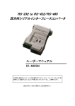
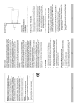
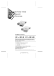
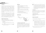
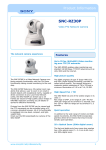
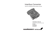
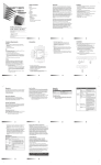
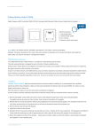
Table of Contents
Overview
Features
Switch Configuration
Operating Modes
Point-to-Point
Multidrop
Simplex
Installation
Appendix
Terminal Block Pin Assignments
DCE/DTE Connection Description
SW2 Pin Assignment Schematics
Troubleshooting
Specifications
Radio & TV Interference
1
2
3
5
5
7
10
12
13
13
13
14
17
18
19
Unpacking
The IC-485SN package contains:
• One IC-485SN Converter
• One User Manual
Check to see if the product has been damaged in shipping. If you encounter a problem, contact your
dealer right away.
©Copyright 1998 ATEN® International Co., Ltd.
Manual Part No. PAPE-0149-100
Printed in Taiwan 11/1998
All brand names and trademarks are the registered property of their respective owners
Overview
The IC-485SN is a bidirectional converter for RS-232 and RS-485/RS-422 interfaces that provides
Point to Point, Multidrop, and Simplex operations. A figure showing the names and locations of its
features is given below:
The operating mode, contention control and RS-232C assignments are all configured with two slide
switches: SW1 and SW2 (details are given in the Switch Configuration section, below).
1
Features
• Data Transmission Controlled by the RTS Signal
• DCE/DTE Selectable
• Point to Point/Multidrop, and Simplex/Duplex Operating Modes
• External Power Not Required - Power Supplied by the RS-232 Interface
• Compact Size
2
Switch Configuration
The IC-485SN is configured by setting two slide switches. SW1 is used to select the IC-485SN’s
Device Mode; SW2 is used to select the IC-485SN’s Transmitting and Receiving Mode, as shown in
the table below:
An explanation of the SW1 and SW2 terms is given in the table below:
3
4
Operating Modes
The IC-485SN supports three operating modes: Point-to-Point, Multidrop, and Simplex. Point-to-Point
and Multidrop can be configured for Full Duplex or Half Duplex operation. Each of the operating
modes is explained below.
Point-to-Point
A Point-to-Point configuration is one in which two devices, located at two different places, are linked
for communication by a pair of IC-485SN units. There are two configurations: Point-to-Point Full
Duplex and Point-to-Point Half Duplex.
1. Point-to-Point 4 Wire Full Duplex
• Point-to-Point Full Duplex uses reverse four wire cabling, as shown in the figure below.
5
• For both IC-485SN units, set SW1 to DCE or DTE depending on what type of device the IC-485SN
will plug into (if it will plug into a DCE device, configure it for DTE, and vice versa).
• For both IC-485SN units, set SW2 to TxON, RxON
2. Point-to-Point 4 Wire Half Duplex
• Point-to-Point Half Duplex uses straight through four wire cabling, as shown in the figure
below:
6
• For both IC-485SN units, set SW1 to DCE or DTE depending on what type of device the IC-485SN
will plug into (if it will plug into a DCE device, configure it for DTE, and vice versa).
• For both IC-485SN units, set SW2 to TxDTR/RTS, RxDSR/ON
Note: TxDTR/RTS, RxDSR/ON transmitting/receiving mode, involves a straight through Data+,
Data-, Busy+, Busy- wiring scheme. See the pin assignment schematic in the Appendix
for more details.
Multidrop
A Multidrop configuration is one in which more than two devices are linked for communication
using several IC-485SN units. Either a two-to-one RJ-11 adapter or a combination of the terminal
block and the RJ-11 jack can be used to connect the IC-485SN units to each other. One of the devices
that one of the IC-485SN units connects to is assigned to be the master device. The remaining
devices that the other IC-485SN units connect to are slave devices. There are two configurations:
Multidrop Full Duplex and Multidrop Half Duplex.
7
1. Multidrop 4 Wire Full Duplex
• Multidrop Full Duplex uses reverse four wire cabling to link all the connected IC-485SN units, as
shown in the figure below:
8
• For all IC-485SN units, set SW1 to DCE or DTE depending on what type of device the IC-485SN
will plug into (if it will plug into a DCE device, configure it for DTE, and vice versa).
• For the Master IC-485SN unit, set SW2 to TxON, RxON
• For all Slave IC-485SN units, set SW2 to TxRTS, RxON
2. Multidrop Half Duplex
• Multidrop Half Duplex uses straight through four wire cabling to link all the connected IC485SN units, as shown in the figure below:
9
• For all IC-485SN units, set SW1 to DCE or DTE depending on what type of device the IC-485SN
will plug into (if it will plug into a DCE device, configure it for DTE, and vice versa).
• For all IC-485SN units, set SW2 to TxDTR/RTS, RxDSR/ON
Note: Only one device at a time can talk on the bus (RTS On); during that time, the other devices
must remain silent (RTS Off). See the explanation regarding TxDTR/RTS, RxDSR/ON in the
table on p. 4.
TxDTR/RTS, RxDSR/ON transmitting/receiving mode, involves a straight through Data+,
Data-, Busy+, Busy- wiring scheme. See the pin assignment schematic in the Appendix
for more details.
Simplex
A Simplex configuration is one in which more than two devices are linked for communication using
several IC-485SN units in a manner similar to a Multidrop configuration. The difference is that in a
Simplex configuration, the master device can only talk, and the slave devices can only listen.
10
• Simplex uses reverse two wire cabling to link all the connected IC-485SN units, as shown in the
figure below:
• For all IC-485SN units, set SW1 to DCE or DTE depending on what type of device the IC-485SN
will plug into (if it will plug into a DCE device, configure it for DTE, and vice versa).
• For all IC-485SN units, set SW2 to TxON, RxON
11
Installation
1. Set the configuration switches (SW1 and SW2) according to the information provided in the Switch
Configuration and Operation sections.
2. Plug the IC-485SN’s DB-25 female connector into the PC’s RS-232C port.
3. Use telephone cable to connect one IC-485SN unit to the other.
a) Use four wire or two wire cable according to the information given in the Operation section.
b) Use reverse or straight through wiring according to the information given in the Operation
section.
c) You can use the RJ-11 telephone jack, or wire directly to the Terminal Block (see the Appendix
for the Terminal Block pin assignments). If you are daisy chaining units, you will need to use
either a two-to-one RJ-11 adapter or a combination of the terminal block and the RJ-11 jack.
4. Power On the PC. The unit is now ready for operation.
12
Appendix
Terminal Block Pin Assignments
DCE/DTE Connection Description
13
SW2 Pin Assignment Schematics
TxON, RxON:
14
TxRTS, RxON:
15
TxDTR/RTS, RxDSR/ON:
16
Troubleshooting
If the above solutions fail to alleviate the problem, contact your dealer for help.
17
Specifications
18
Radio & TV Interference
Warning. This equipment generates, uses and radiates radio frequency energy and if not installed
and used in accordance with the instruction manual may cause interference to radio and television
reception. It has been tested and found to comply with the limits for a Class A computing device in
accordance with the specifications in Subpart J of Part 15 of the FCC Rules, which are designed to
provide reasonable protection against such interference when operated in a commercial
environment. Operation of this equipment in a residential area is likely to cause interference, in
which case the user at his own expense will be required to take whatever measures may be required
to correct the interference.
If this equipment does cause interference to radio or television reception, which can be determined
by turning the equipment off and on, the user is encouraged to try to correct the interference by one
or more of the following measures:
1. Reorient the receiving antenna.
2. Relocate the computer with respect to the receiver.
3. Move the computer away from the receiver.
4. Plug the computer into a different outlet so that the computer and receiver are on different branch circuits.
19
5. Ensure that the mounting screws, attachment connector screws and ground wires are tightly secured.
6. Ensure that good quality shielded and grounded cables are used for data communications.
If necessary, the user should consult the dealer or an experienced radio/television technician for
additional suggestions.
20